Table of Contents
Advertisement
Quick Links
Advertisement
Table of Contents

Related Manuals for Vesta BOGP-3-G2


Summary of Contents for Vesta BOGP-3-G2
- Page 1 BOGP-3-(EX)-G2 Cellular & GPRS Alarm System User Manual April 15-2022...
-
Page 2: Table Of Contents
Table of Contents 1. Application Overview __________________________________________________________ 5 1.1. Parts Identification _______________________________________________________ 5 1.2. Introduction _____________________________________________________________ 6 1.3. The Power Supply ________________________________________________________ 6 1.4. System Deployment ______________________________________________________ 6 1.5. How to Install the Control Panel ____________________________________________ 6 1.6. Multi-User Passwords ____________________________________________________ 7 1.7. - Page 3 3.8. General Setting _________________________________________________________ 25 3.9. Device +/- ______________________________________________________________ 25 4. Operation ___________________________________________________________________ 26 4.1. LCD Display ____________________________________________________________ 26 4.2. Entering User Menu _____________________________________________________ 26 4.3. Away Arm Mode ________________________________________________________ 26 4.4. Home Arm Mode ________________________________________________________ 27 4.5. Force Arm _____________________________________________________________ 27 4.6.
- Page 4 6. Appendix ___________________________________________________________________ 61 6.1. Fault Event Description __________________________________________________ 61 6.2. SMS Remote Command __________________________________________________ 62 6.3. Control Panel Mode and Response Table ___________________________________ 67 6.4. Event Code ____________________________________________________________ 69...
-
Page 5: Application Overview
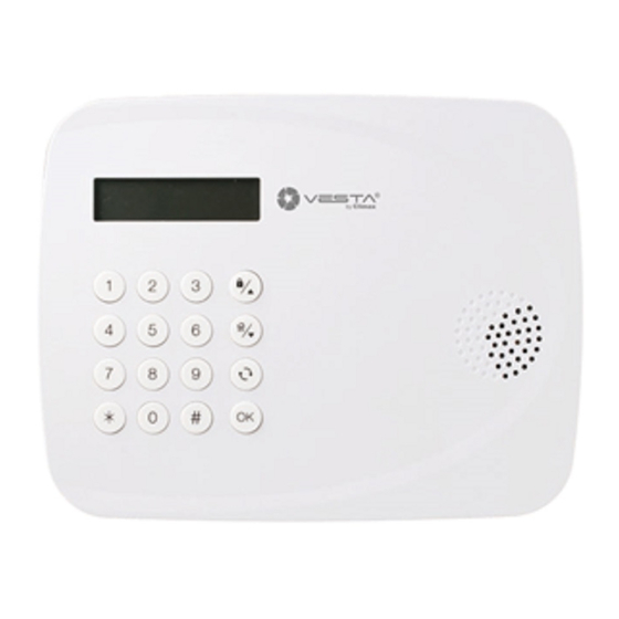
1. LED Indicator (Green) 1. Application Overview This LED is light on when any key is 1.1. Parts Identification pressed to wake up the panel. 2. Fault Indicator (Orange) Front View When the panel is awake, this LED is light on if there is at least one fault in the system. -
Page 6: Introduction
This manual covers installation, programming, and control of the BOGP-3 control panel. BOGP-3-G2-2G: cellular & GPRS alarm Secure the back cover by fixing screws. system with 2G reporting. BOGP-3-G2-4G: cellular & GPRS alarm system with 4G reporting. -
Page 7: Multi-User Passwords
devices and accessories programmed on a 1.6. Multi-User Passwords tabletop before locating and mounting them. Step 1. Loosen the screw at bottom of the In order to provide maximum security when panel (Figure 1). operating the system, the Control Panel offers different levels of authorization for various Step 2. -
Page 8: System Basic Operation
Temporary Code If the Control Panel lost power supply. When the power is restored, it will The Temporary Code is designed for the resume its previoius mode. use of occasional visitors. It has the When programming settings, refer to the same authorization level as the User PIN following tables to enter symbols and Code, but will be removed after one... -
Page 9: System Configuration
2. System Configuration 2.2. Install Code This function is for you to edit the Installer code In order to configure the Control Panel setting, you need to enter the Installer Menu. To enter Step 1. Select Install Code and press OK to the Installer Menu: confirm. -
Page 10: Test Report
setting, you will be asked to enter an Step 2. The Control Panel will send a test account number. report to the first reporting destination. Step 5. Enter the IP address for IP reporting, telephone/mobile number for SMS 2.5. Test Siren reporting, or email address for email reporting Use the function to test both Control Panel’s... -
Page 11: Panel Setting
A P N E d i t H i g h T e m p R p t . i n t e r n e t L o w T e m p R p t . Q u i c k K e y Step 3. - Page 12 - 9 ° C This is for you to set the interval time the Control Panel waits before making a regular . . . check-in report to the programmed reporting ° C destination. Factory Default is set to 6 hours. Step 2.
-
Page 13: General Setting
and under exit timer countdown, if a opened A d e l a i d e Door Contact set to Entry attribute is closed, B r i s b a n e the system will automatically arm the system D a r w i n even if the exit delay timer has not expired yet. - Page 14 expires, the Control Panel will report a burglar Step 1. Select Entry Time and press OK to alarm immediately when the Entry Delay time confirm. expires. A w a y A r m H o m e A r m On: When set to On, if an Entry Delay countdown is activated and the Control Panel Step 2.
-
Page 15: Device
Panel will sound beeping sounds Supervision when during Exit Delay Timer for Set the supervision timer for accessory Away Arm mode. devices, if no supervision signal is received within set duration for a certain device, the Exit Home: If not turned off, the Control Panel will report the situation Control Panel will sound beeping accordingly. - Page 16 Edit Device S e t / U n s e t S i l e n t P a n i c Use this function edit the devices learnt into the P e r s o n a l A t t .
- Page 17 device is triggered, the Control When the system is in Home Panel will not respond. Arm mode, if an “Interior” device is triggered, the Control Exit Delay: Panel will not respond. When the system is counting Away and Home Arm Entry down Exit Delay Timer, if a Delay: “Interior, Follower”...
- Page 18 Panel will not respond. Entry Time expires, the Control Panel will not respond. When the system is counting Exit Delay: down Home Arm Entry Delay Timer, “Interior with When the system is counting Delay” device is triggered, the down Exit Delay Timer, if an Control Panel will not respond.
- Page 19 expires, the Control Panel will Alarm” immediately. not respond. Water Exit Delay: The Water device is active all When the system is counting the time regardless of system down Exit Delay Timer, if a mode or Entry / Exit Time. When “Home/Delay”...
- Page 20 scene number selection to take effect. D o o r ( F r o n t ) D o o r ( B a c k ) D i s a b l e G a r a g e S c e n e 1 G a r a g e d o o r...
-
Page 21: Network Setting
Program your network and email SMTP setting Program Siren under this menu. The program siren functions allows you to Step 1. Select Network Set., press OK to learn in siren/bellbox and program their confirm behaviour. S M T P L e a r n S i r e n F r o m... -
Page 22: Media Upload
From setting must be entered in all Email: order send lowercase letters. picture/video by email, the SMTP and From setting must be completed first. HPS/XMPP Step 4. If you choose to delete the setting, the The HPS/XMPP setting is for you to register current upload setting will be removed. - Page 23 Step 4. According to the condition selected, set the detail of the condition and press OK to confirm. Mode Change The rule will be activated when the Control Panel enters selected mode. Alarm The rule will be activated when the selected alarm is triggered.
-
Page 24: Programming Menu
1 0 ) ..3. Programming Menu Step 3. For an existing PIN code, you will be The programming menu is designed for user to asked whether you want to delete the mange User PIN codes and other setting. to PIN code (except for PIN code 1 which enter the Programming Menu: cannot be deleted), press OK to... -
Page 25: Master Code
Code setting is now complete Station to indicate of a “Duress Situation in Progress”. To set the Duress Code: L a t c h L a t c h O f f Step 1. Select Duress Code and press OK to confirm. -
Page 26: Operation
4. Operation Step 1. The screen will display: 4.1. LCD Display S T A R T The Control Panel’s LCD will display the Step 2. Press Down key to scroll through the system information according to different status fault events. When all fault events are and panel modes. -
Page 27: Home Arm Mode
User PIN code and press the Home When under Disarm mode, enter a Arm key on the Control Panel. User PIN code and press the Away Arm key on the Remote Keypad. When under Disarm mode, enter a (Please refer to Remote Keypad User PIN code and press the Home manual for detail) -
Page 28: Disarm
Step 1. Select Apply Scene, press OK to 4.6. Disarm confirm. The screen will display scene When the system is under Away Arm or Home numbers from 1~10 along with Scene Arm mode, to disarm the system: name: Step 1: ... -
Page 29: Keypad Lockdown
Panel. An additional tamper switch can be that triggered alarm will connected to the External Tamper Switch displayed on screen. Use the Down Terminal on the Control Panel. The terminal button to scroll down the alarm event, will form a Normal Close loop with the tamper the screen will display whether the switch and activate when the loop is opened. -
Page 30: Battery Level
learnt in devices for the Control Panel and key to exit fault display. return all configuration to factory default by following the below steps <NOTE> Step 1. Power down Control Panel. Control Panel capable Step 2. Apply power to the control panel. detecting following fault events: Step 3. -
Page 31: Connecting To Pc Programming Webpage
5. Connecting to PC Programming Webpage 5.1. Hardware Installation BOGP-3 can be programmed via USB port connection of a computer using the PC Programming Tool software. Follow the hardware installation steps below: Step 1. Using the programming cable, connect one end to the micro USB port on the panel, and the other end to the USB port on your computer. - Page 32 Step 2. Select the serial port in connection with your panel. There should be a newly-added port on the dropdown menu. Select the port. You can also click to search the port. Step 3. Choose the corresponding device in the HW/SW section. Step 4.
- Page 33 If there is still a problem on connection, you can try the following ways to resolve it: Change TCP port. For example, change the TCP port to 55080. Close the firewall on your computer, or create an inbound port rule for the connection. You can refer to the following page if you need instructions: https://docs.microsoft.com/en-us/windows/security/threat-protection/windows- firewall/create-an-inbound-port-rule...
-
Page 34: System Settings
5.3.2. System Settings 5.3.2.1. User User Code The User Codes are used for users to access the alarm system. A total of 10 4-digit User Codes can be stored in BOGP-3. Each individual User can be given a name for easy recognition when viewing system events. - Page 35 The Duress Code is used to access the system in duress situation. When this code is used for accessing the system, the Control Panel will report a secret alarm message without sounding the siren to the Central Monitoring Station to indicate of a “Duress Situation in Progress”.
- Page 36 For Example: ip://6543@59.124.123.22:8765/CID ip:// 6543 @59.124.123.23 :8765 /CID Reporting Account Server IP Port Reporting type (4-8 digits) address number Format IP/GPRS reporting in SIA format: Reporting destination format: ip://Account@Server IP:Port/SIA For Example: ip://6543@59.124.123.22:8765/SIA ip:// 6543 @59.124.123.23 :8765 /SIA Reporting Account Server IP Port...
- Page 37 The reporting priority is based on group number sequence. From Group 1 Group Group 2 Group 3 ….etc When more than one reporting destinations are assigned to a group, if a report is sent to one of the destinations successfully, the system will stop reporting to the rest of the reporting destination in the same group and move on to report to the next group.
- Page 38 The Keyword is used for receiving SMS commands from users. When a user sends a SMS command to the Control Panel through Vesta EZ Home mobile application, the correct keyword must be entered along with a valid User PIN code for the Control Panel to recognize the command.
- Page 39 temperature drops below the threshold. When the temperature rises above set value again, the Control Panel will stop alarming and send Low Temperature Restore report. IR Camera Alarm Image This is to select the resolution and number of pictures taken by PIR Camera when the camera detects a movement in armed mode.
- Page 40 Backup: Click “Backup configuration by saving as file” to download your current panel configuration as a .bin file into your computer. Restore: Select the saved .bin file in your computer, then click “Restore” to restore your panel configuration according to the file. <NOTE>...
- Page 41 events. Tamper Alarm Away Arm: Tamper alarm will only be activated when tamper switch is triggered under Away Arm mode (Tamper event will still be reported normally in Home/Disarm mode). Always: Tamper alarm will be activated whenever tamper switch is triggered. ...
- Page 42 Exit Home: If not disabled, the Control Panel will sound beeping sounds when during Exit Delay Timer for Home Arm mode. Warning Beep: If not disabled, the Control Panel will sound beeping sounds every 30 seconds when fault exists within system. ...
- Page 43 Here you can program the user name and password used for accessing the webpage. Web User: This is the user name you entered when you access the panel webpage. Default web user is “admin”. If you want to change the user name, enter a new name in the field.
- Page 44 APN (Access Point) Name It is the name of an access point for GPRS. Please inquire your service provider for an APN. When APN is set, the system becomes valid for internet connection. User (GPRS) It is the Log-in name to input before accessing the GPRS feature. Please inquire your service provider for information.
-
Page 45: Device Management
5.3.3. Device Management This page for you to learn in, edit, delete and control all the accessory devices. A total of 50 devices can be learnt into the system. 5.3.3.1 Learning Step 1. Under Disarm Mode, press “Start Learning”. The Control Panel will enter learning webpage. - Page 46 Step 5. The Control Panel will display “Updated Successfully” message and the new learned in device zone accordingly. The device is now learn in to the system. Step 6. You can click “Stop” button to leave learning mode, the Control Panel will return to normal mode.
- Page 47 Step 2. Enter the device’s RF code Step 3. Enter device name. Step 4. Click “Add RF Device ” to include the device in the system. 5.3.3.3 Walk Test Step1. Press “Start Walk Test” under either Learning or Device Management webpage. The Control Panel will enter Walk Test page.
- Page 48 Step1. Under Device Management webpage, click “Edit”. The Control Panel will enter device editing page. Step2. Proceed to edit device settings, click “Submit” when you are satisfied with all settings or information. Name: Enter a name for the device, A maximum of 20 characters are allowed ...
- Page 49 When the system is in Away and Home Arm mode, or counting down Entry / Exit Delay Timer, if a “Perimeter” device is triggered, a “Burglar Alarm” will be activated immediately and reported. Perimeter, Follower Away and Home Arm Mode: ...
- Page 50 is triggered, the Control Panel will not respond. Interior with Delay Away and Home Arm Mode: When the system is in Away Arm mode, if an “Interior with Delay” device is triggered, the Control Panel will start an Entry Delay countdown timer according to Entry 1 Delay setting programmed for the user to disarm the system.
- Page 51 Exit Delay: When the system is counting down Exit Delay Timer, if an “Entry1” or “Entry 2” device is triggered, the Control Panel will not respond. Home/Delay Away and Home Arm Mode: When the system is in Away Arm mode, if a “Home/Delay” device is triggered, a “Burglar Alarm”...
- Page 52 Medical Emergency The Medical Emergency device is active all the time regardless of system mode or Entry / Exit Time. When a Medical Emergency device is triggered, the Control Panel will activate and report a “Medical Alarm” immediately. ...
- Page 53 Chime: When Chime function is enabled, if the device is triggered under Disarm mode, the Control Panel will emit a ding-dong Door Chime sound to notify user. If the function is not disabled, no sound will be emitted. Please refer to 5.3.2.4. Area for detail. <NOTE>...
-
Page 54: Captured Events
by selecting “Off” and click “Test” again. <NOTE> When you are changing Siren batteries or moving Siren mounting location, you need to first deactivate the siren by selecting Bypass is siren edit screen, then turn off the Siren Tamper to avoid accidental tamper trigger. 5.3.4. -
Page 55: History Records
Test to check signal strength. Timeout: The PIR Camera did not respond to Control Panel. Please check if the PIR Camera is out of order or under Low Battery, then perform Walk Test to check signal strength. <NOTE> If a PIR Camera is triggered when the system is armed. Do not disarm the alarm system before the status displays “Upload”... -
Page 56: Panel Control
5.3.5.2 Reported Event The reported event history are recorded in this page. A total of 250 reported events can be recorded with Time, Event, CID Event Code, Device Group/Zone, User information and Status. Time: The time when the Control Panel begins the report ... -
Page 57: Home Automation
Current Mode Control Panel current mode. Away Arm: Away Arm will arm all devices in the system to raise alarm when activated. Home Arm: Home Arm will partially arm the system according to device attribute setting to allow free movement within part of the house while still keeping the system perimeter protected. - Page 58 Step2. Set the Rule Condition. Mode Changed: The rule will be activated when the system mode is change to set mode. Alarm: The rule will be activated when the set alarm event is triggered. Greater Temp: The rule will be activated when temperature reading from any of the sensor in the system rises above set value.
-
Page 59: Firmware
Step2. Set the Execution Actions, up to 3 actions can be included in a scene. Request Image Zone: The PIR Camera at specified zone will take a picture. Mode Change To: The Control Panel will change to selected system mode. Step3. -
Page 60: Rf Firmware
5.3.9. RF Firmware This page is for you update your Control Panel’s RF firmware. Step1. Select the latest RF firmware file in your computer Step2. Click “Submit” to upload the firmware file to Control Panel. Step3. It takes several minutes to complete update, do NOT power off during the process. Step4. -
Page 61: Appendix
6. Appendix 6.1. Fault Event Description During operation, when the panel detects faulty events, the panel will log the event and make reports. Users can check fault events from Fault Display in User Menu. Please refer to 4.13 Fault Display. ... -
Page 62: Sms Remote Command
6.2. SMS Remote Command Control Panel with GSM function can be controlled remotely by SMS Commands for arm/home/disarm action and setting configuration. BOGP-3 can be programmed by receiving these commands when XMPP connection is enabled. Please refer to 2.10 Network setting and following information for details. - Page 63 Error: The SMS Confirmation Message = USRS:ERROR SMS Command Table Command Comment Example & Descriptions ECHO Test panel PROG 7982 ECHO: PROG 7982 USRS:1,1,1234,user,1 Parameter 1: Enter 1 Parameter 2: User ID 1~10 = User PIN Code# 95 = Guard Code Change user 96 = Master Code...
- Page 64 8 = Entry1 9 = Interior with Delay 10 = 24 Hours 11 = Fire 12 = Medical Emergency 13 = Water 14 = Set/Unset 15 = Silent Panic 16 = Personal Attack 17 = Trigger Scene 18 = Silent Burglar 19 = Entry2 Parameter 8: PSS groups in bitwise hex string, BIT1 to BIT8 for Group 1~8, keep blank for non-PSS devices.
- Page 65 4 = New York 5 = Moncton 6 = London 7 = Paris 8 = Istanbul 9 = Moscow 10 = Taipei 11 = Tokyo 12 = Sydney 13 = Auckland 14 = Adelaide 15 = Brisbane 16 = Darwin PROG 7982 REST:5 REST...
- Page 66 Change web PROG 7982 WBSC:admin,admin1234 WBSC username / Parameter 1: Web username password Parameter 2: Password PROG 7982 XMPP:xmpp://user:password@192.168.0.190:5222,domain,admin,40 Change Parameter 1: XMPP server URL XMPP XMPP setting Parameter 2: XMPP server domain Parameter 3: Buddy list Parameter 4: Ping interval in seconds (10~60) PROG 7982 GAPN:internet,, Change...
-
Page 67: Control Panel Mode And Response Table
6.3. Control Panel Mode and Response Table For Alarm Activation by Events and Control Panel Responses, please refer to the following table: System Mode / Status Attribute Under Under Exit Under Home Disarm Mode Away Mode Home Mode Away Entry Timer Entry Timer Timer... - Page 68 Instant Fire Instant Fire Instant Fire Instant Fire Instant Fire Instant Fire Fire Alarm Alarm Alarm Alarm Alarm Alarm Instant Instant Instant Instant Instant Water Instant Water Water Water Water Water Water Alarm Alarm Alarm Alarm Alarm Alarm Instant Instant Instant Instant Instant...
-
Page 69: Event Code
133 – 24 Hours 6.4. Event Code When a device set as 24 Hour is 100 – Medical triggered. 101 – Personal emergency 136 – Burglar Outdoor When Wrist Transmitter When a Burglar Outdoor Alarm is Emergency Pendant (WTR) - Page 70 384 – Device Low Battery When a device’s is under low battery. 389 – Self Test Failure – Arm/Disarm Remote Controller) When system armed disarmed using Remote Controller. 401 – Arm/Disarm by Panel When system armed disarmed by entering the PIN code.
Need help?
Do you have a question about the BOGP-3-G2 and is the answer not in the manual?
Questions and answers