Table of Contents
Advertisement
Quick Links
Advertisement
Table of Contents

Related Manuals for TQ ILM-E

Summary of Contents for TQ ILM-E
- Page 1 Assembly Instructions ILM-E Servo Kits Edition 10/2021 EN...
- Page 2 (see section 1.12 on page 7). Copyright © TQ-Systems GmbH TQ-Drives is a trademark of the TQ-Group. TQ-Systems GmbH | Mühlstr. 2, Gut Delling | 82229 Seefeld | Germany Phone: +49 8153 9308-0 | Fax: +49 8153 4223 info@tq-group.com | www.tq-robodrive.com...
-
Page 3: Table Of Contents
2.2 Target group ......................8 2.3 Intended use ......................9 2.4 Working environment and operation ..............9 2.5 Safety instructions for the ILM-E servo kit ............10 2.6 Warning labels ......................11 3 Technical data ........................12 3.1 Data sheet ......................... 12 3.2 Connection diagram (star-serial configuration) ............ -
Page 4: Introduction
The implementation of customer-specific solutions to achieve a compact and thermal- ly-optimized design is supported by extensive documentation and RoboDrive develop- ment expertise. ILM-E servo kits offer the following stand-out features: — Installation kits for maximum freedom of design — Hollow shaft capability —... -
Page 5: Revision Index
► This symbol indicates an action to be taken. — This symbol indicates a list. 1.6 Training The manufacturer offers training courses on the general handling of the ILM-E servo kits. Please contact the TQ-Drives division of TQ-Systems GmbH as required. -
Page 6: Warranty
1.10 Transportation and storage — The stator and rotor of the ILM-E servo kit are shipped in separate packing units. — Always transport the ILM-E servo kits in the original packaging to avoid mechanical damage or damage due to static electricity. -
Page 7: Environmentally-Friendly Disposal
The life of persons with passive or active implants such as pacemakers, defibrillators, insu- lin pumps etc. is put at risk if they stand in the vicinity of the ILM-E servo kit. ► Make sure that no persons who could possibly be affected by powerful magnetic fields are able to approach the ILM-E servo kit. -
Page 8: Safety
Safety Assembly Instructions | ILM-E Servo Kits 2 SAFETY These instructions contain notes that you must follow for your own personal safety and to avoid injury and damage to property. They are highlighted by warning triangles and are shown as follows according to the level of danger. -
Page 9: Intended Use
Assembly Instructions | ILM-E Servo Kits 2.3 Intended use The ILM-E servo kits must be used only for the applications listed in the technical de- scriptions, i.e. as a structurally-integrated drive. Any different or more extensive usage will be regarded as contrary to the intended use and will invalidate the warranty. -
Page 10: Safety Instructions For The Ilm-E Servo Kit
The life of persons with passive or active implants such as pacemakers, defibrillators, insu- lin pumps etc. is put at risk if they stand in the vicinity of the ILM-E servo kit. ► Make sure that no persons who could possibly be affected by powerful magnetic fields are able to approach the ILM-E servo kit. -
Page 11: Warning Labels
Assembly Instructions | ILM-E Servo Kits — The ILM-E servo kit reaches high temperatures during operation. If there is a thermal bridge between the housing and the ILM-E servo kit installed in it, there is a risk of burns on the housing surface. -
Page 12: Technical Data
Technical data Assembly Instructions | ILM-E Servo Kits 3 TECHNICAL DATA 3.1 Data sheet You will find the technical data for the ILM-E servo kits in the data sheet provided in the ILM-E servo kits download area. 3.2 Connection diagram (star-serial configuration) Connections A, B and C can be found on the ILM-E servo kit. -
Page 13: Installation Dimensions
Table 2: Measuring points on the ILM-E servo kit (star-serial configuration) 3.3 Installation dimensions The installation dimensions of the ILM-E servo kit are shown in the relevant drawing which can be found in the download area for the product concerned. -
Page 14: Solder Pads On The Connection Board
4 SOLDER PADS ON THE CONNECTION BOARD Fig. 4 shows the solder pads on the connection board by way of example. Detailed drawings for your specific ILM-E servo kit can be found on our website. Fig. 4: Solder pads on the connection board... -
Page 15: Assembly
The life of persons with passive or active implants such as pacemakers, defibrillators, insu- lin pumps etc. is put at risk if they stand in the vicinity of the ILM-E servo kit. ► Make sure that no persons who could possibly be affected by powerful magnetic fields are able to approach the ILM-E servo kit. - Page 16 ► Never detach electrical connections on the ILM-E servo kit or the inverter while they are live. ► Use a permitted meter to check that the power connections are voltage-free before you carry out installation work on the device.
-
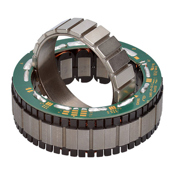
Page 17: Stator
Assembly Assembly Instructions | ILM-E Servo Kits 5.1 Stator 5.1.1 Tools and equipment required — Non-magnetic tool — Cleaning agents — Antistatic coat — ESD grounding wrist strap — Safety goggles — Protective gloves — Assembly sleeve — Drawing available as a download —... -
Page 18: Shrink-Fitting
Assembly Assembly Instructions | ILM-E Servo Kits 5.1.2 Shrink-fitting WARNING Danger of burns on hot surfaces Contact with the housing at the temperatures required for shrink-fitting can cause severe burns. ► Wear appropriate heat protection for your hands throughout the entire process. - Page 19 Assembly Assembly Instructions | ILM-E Servo Kits — Remove the housing from the oven and align the stator in the housing as shown in the design guidelines. ◀ Dowel pin Fig. 7: Stator alignment — Use the press-in tool to carefully press the stator into the housing until the pole cap/base of the stator touches the bottom surface of the housing.
-
Page 20: Rotor
Assembly Assembly Instructions | ILM-E Servo Kits ◀ Dowel pin ◀ Dowel pin Fig. 9: Final stator position — Allow the housing to cool to room temperature. — Once the housing has cooled to room temperature, check that the stator is seated firmly and without gaps in the housing. -
Page 21: Bonding Process
Assembly Assembly Instructions | ILM-E Servo Kits 5.2.2 Bonding process ► Clean and degrease the bonding surfaces on the shaft (item 1 in Fig. 10) and rotor (item 1 in Fig. 11) following the adhesive manufacturer’s instructions. ► Heat the rotor for 5 minutes at 60 °C in the curing oven. -
Page 22: Inserting The Rotor Into The Stator
Assembly Assembly Instructions | ILM-E Servo Kits 5.2.3 Inserting the rotor into the stator WARNING Danger of crushing, catching or cutting injuries to the hands. For example, the rotor can move suddenly under the effect of magnetic forces. This can result in severe injuries. -
Page 23: Declaration Of Incorporation
Declaration of incorporation Assembly Instructions | ILM-E Servo Kits 6 DECLARATION OF INCORPORATION Declaration of Incorporation according to Annex IIB, 2006/42/EC W e e Company name: TQ Systems GmbH Postal code, city: 82229 Seefeld, Germany Postal address: Mühlstr. 2, Gut Delling... - Page 24 TQ-Systems GmbH | TQ-Drives Mühlstr. 2, Gut Delling | 82229 Seefeld | Germany Phone: +49 8153 9308-0 | Fax: +49 8153 4223 info@tq-group.com | www.tq-robodrive.com...
Need help?
Do you have a question about the ILM-E and is the answer not in the manual?
Questions and answers