Table of Contents
Advertisement
Advertisement
Table of Contents

Related Manuals for TQ ILM Series

Summary of Contents for TQ ILM Series
- Page 1 Assembly Instructions ILM Servo Kits Edition 03/2021 EN...
- Page 2 Copyright © TQ-Systems GmbH TQ-Drives is a trademark of the TQ Group. Document item no.: 304188.0200 TQ-Systems GmbH | Mühlstr. 2, Gut Delling | 82229 Seefeld | Germany Phone: +49 (0) 8153 9308-0 | Fax: +49 (0) 8153 4223 info@tq-group.com | www.tq-robodrive.com...
-
Page 3: Table Of Contents
1.1 Notes on the assembly instructions ................. 5 1.2 Description ........................ 5 1.3 System components available from TQ-Drives ............6 1.3.1 Example with system components for hollow shaft motors ......6 1.3.2 Example with system components for solid shaft motors ......7 1.4 Revision index ...................... - Page 4 Assembly Instructions | ILM Servo Kits 7 Assembly ........................... 19 7.1 Bonding surfaces on stator and rotor ..............21 7.2 Tools and equipment required ................21 7.3 Bonding instructions ....................22 7.3.1 Stator ....................... 22 7.3.2 Rotor ....................... 24 7.3.3 Double rotor ....................25 7.4 Inserting the rotor into the stator ................
-
Page 5: Introduction
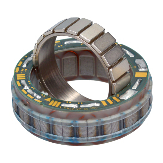
► Follow ALL danger and warning instructions and notes on precautionary measures. ► Read section „2 Safety“ on page 10 carefully. 1.2 Description RoboDrive’s ILM series of stator-rotor installation kits provides solutions for structurally integrated drive engineering. An ILM (internal rotor motor) -
Page 6: System Components Available From Tq-Drives
— High bandwidth and minimal harmonics for optimal control quality 1.3 System components available from TQ-Drives TQ-Drives RoboDrive is a complete drive technology supplier, offering the servo kit, motors and motor-gearbox units right through to customised drive systems. 1.3.1 Example with system components for hollow shaft motors Fig. -
Page 7: Example With System Components For Solid Shaft Motors
Assembly Instructions | ILM Servo Kits Introduction 1.3.2 Example with system components for solid shaft motors Fig. 3: Example with system components for solid shaft motors Item Designation Solid shaft motor with integrated safety brake ILM servo kit Safety brake Absolute position sensor 1.4 Revision index Manual... -
Page 8: Explanation Of The Symbols Used
— There is a tape with label and serial number attached to the rotor. 1.10 Warranty TQ-Systems GmbH guarantees that, if used for the agreed purpose, the ILM servo kits fulfil the contractually defined specifications and functionality and correspond to the state of the art at the time of delivery. -
Page 9: Transportation And Storage
Assembly Instructions | ILM Servo Kits Introduction 1.11 Transportation and storage — The stator and rotor of the ILM servo kit are shipped in separate packing units. — Always transport the ILM servo kits in the original packaging to avoid mechanical damage or damage due to static electricity. -
Page 10: Safety
Safety Assembly Instructions | ILM Servo Kits 2 SAFETY These instructions contain notes that you must follow for your own personal safety and to avoid injury and damage to property. They are highlighted by warning triangles and are shown as follows according to the level of danger. 2.1 Hazard classification DANGER The signal word designates a hazard with a high degree of risk which, if it is not avoided,... -
Page 11: Intended Use
If the ILM servo kits are to be used safely and without interruption, they must have been correctly transported, stored, assembled and set up. For any use contrary to the intended use, TQ-Systems GmbH shall accept no liability for any damage that may occur and offers no warranty that the product will work perfectly and correctly. -
Page 12: Safety Instructions For The Ilm Servo Kit
Safety Assembly Instructions | ILM Servo Kits 2.5 Safety instructions for the ILM servo kit DANGER Danger of death by powerful magnetic fields. The life of persons with passive or active implants such as pacemakers, defibrillators, insu- lin pumps etc. is put at risk if they stand in the vicinity of the ILM servo kit. ►... -
Page 13: Warning Labels
Assembly Instructions | ILM Servo Kits Safety — The ILM servo kit reaches high temperatures during operation. If there is a thermal bridge between the housing and the ILM servo kit installed in it, there is a risk of burns on the housing surface. —... -
Page 14: Technical Data
Technical data Assembly Instructions | ILM Servo Kits 3 TECHNICAL DATA 3.1 Data sheet You will find the technical data for the ILM servo kits in the data sheet provided in the ILM servo kits download area. 3.2 Connection diagram (star-serial configuration) Connections A, B and C can be found on the ILM servo kit. -
Page 15: Installation Dimensions
Assembly Instructions | ILM Servo Kits Technical data 3.3 Installation dimensions 25x04 25x08 38x06 38x12 50x08 50x14 70x10 Outer diameter stator D js8 [mm] Board diameter 23.8 23.8 36.2 36.2 47.6 47.6 66.8 G [mm] Winding head 23.8 23.8 47.6 47.6 diameter g [mm] Stator length L [mm]... -
Page 16: Ilm Servo Kit Configurations
ILM servo kit configurations Assembly Instructions | ILM Servo Kits 4 ILM SERVO KIT CONFIGURATIONS 4.1 Basic servo kit with connection board Possible configurations: — Star-serial — Star-parallel — Delta-serial — Delta-parallel A temperature sensor is included as standard. Fig. 6: Basic servo kit with connection board 4.2 Servo kit with Hall commutation Basic servo kit with:... -
Page 17: Solder Pads On The Connection Board
Assembly Instructions | ILM Servo Kits Solder pads on the connection board 5 SOLDER PADS ON THE CONNECTION BOARD Fig. 9 shows the solder pads on the connection board by way of example. Detailed drawings for your type of ILM servo kit are available on our website. Phase B Notch Phase C... -
Page 18: Reference Design For Ilm Servo Kits
The design specifications for the specific type of ILM servo kit are contained in the “Drawing ILM XXxXX” drawings which are available on our website. Joining of the rotor and shaft or stator and housing can also be carried out by TQ-Drives, if required. Stator... -
Page 19: Assembly
Assembly Instructions | ILM Servo Kits Assembly 7 ASSEMBLY DANGER Danger of death by powerful magnetic fields. The life of persons with passive or active implants such as pacemakers, defibrillators, insu- lin pumps etc. is put at risk if they stand in the vicinity of the ILM servo kit. ►... - Page 20 Assembly Assembly Instructions | ILM Servo Kits DANGER Danger of death by electric shock or arcing at the power connections of the ILM servo kit The contacts of the power connections carry potentially fatal voltages and high current strengths. Removing the cables to the power connections of the ILM servo kit during oper- ation can cause arcing, resulting in serious or fatal injury.
-
Page 21: Bonding Surfaces On Stator And Rotor
Fig. 11: Bonding surfaces on stator and rotor 7.2 Tools and equipment required — Non-magnetic tool — Centring guides for rotor and stator — TQ-Drives stator bonding kit with: — Dispensing gun (25/50 ml) — Thermally conductive adhesive (e.g. LOCTITE Hysol 9497, 50 ml) — Mixing tube —... -
Page 22: Bonding Instructions
► Read and follow the safety data sheets provided with the adhesive. 7.3.1 Stator Fig. 12: Bonding the stator in position ► Assemble the bonding kit for the TQ-Drives stator. ► Clean and degrease the bonding surfaces (see Fig. 11 on page 21) following the adhesive manufacturer’s instructions. - Page 23 Assembly Instructions | ILM Servo Kits Assembly ► Cure the adhesive for approx. 10 minutes in the curing oven. Make sure that no ex- cess adhesive can bond to the floor of the curing oven. ► Attach the 0.9 mm dispensing needle to the disposable syringe. ►...
-
Page 24: Rotor
Assembly Assembly Instructions | ILM Servo Kits 7.3.2 Rotor ► Clean and degrease the bonding surfaces on the shaft (item 1 in Fig. 13) and rotor (item 1 in Fig. 14) following the adhesive manufacturer’s instructions. ► Heat the shaft for 5 minutes at 60 °C in the curing oven. -
Page 25: Double Rotor
Assembly Instructions | ILM Servo Kits Assembly 7.3.3 Double rotor A double rotor is needed for some versions of the ILM servo kits, for example some with Hall commutation. For this purpose, the rotor length is extended so that the rotation can be detected by the Hall sensors on the connection board. -
Page 26: Declaration Of Incorporation
Declaration of incorporation Assembly Instructions | ILM Servo Kits 8 DECLARATION OF INCORPORATION Edition 03/2021 EN... - Page 27 Assembly Instructions | ILM Servo Kits Edition 03/2021 EN...
- Page 28 Document item no.: 304188.0200 TQ-Systems GmbH | TQ-Drives Mühlstr. 2, Gut Delling | 82229 Seefeld | Germany Phone: +49 (0) 8153 9308-0 | Fax: +49 (0) 8153 4223 info@tq-group.com | www.tq-robodrive.com...
Need help?
Do you have a question about the ILM Series and is the answer not in the manual?
Questions and answers