
Related Manuals for Mimosa 0151858

Summary of Contents for Mimosa 0151858
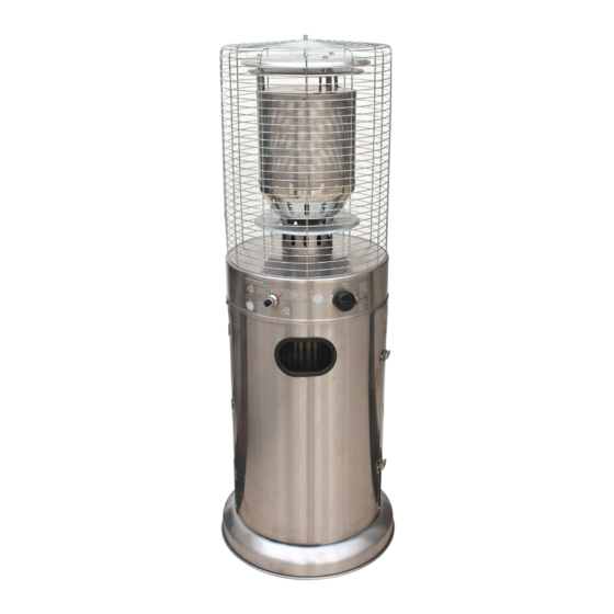
- Page 1 OUTDOOR GAS AREA HEATER -STAINLESS STEEL Provides warmth and ambiance for outdoor settings AGA Gas Certified 0151858 0151858 SAH004-ODS-SS#201 Important: Please retain these instructions for future use...
- Page 2 Gas Leak Test Gas connections on the heater are leak tested at the factory prior to shipment. A complete gas tightness check must be performed due to possible mishandling in shipment or excessive pressure being applied to the heater gas connections. 1.Make a soap solution of one part liquid detergent and one part water.
-
Page 3: Table Of Contents
Table Of Contents Caution............Page 1 Heater Stand and Location......Page 2 Gas Requirements.........Page 4 Leakage Test..........Page 4 Operation and Storage.........Page 5 Cleaning and Care ........Page 6 Parts and Specifications ........ Page 6 Assembly Parts and Procedures ....Page 7 Assembly Steps ..........Page 8 Pilot Service ............ -
Page 4: Caution
Caution PLEASE READ CAREFULLY THE FOLLOWING SAFETY GUIDELINES BEFORE OPERATION. This patio heater is not for commercial use. Do not use the patio heater for indoors, as it may cause personal injury or property damage. Do not place articles on or against this appliance Do not use or store flammable materials near this appliance Do not spray aerosols in the vicinity of this appliance while it is in operation This outdoor heater is not intended to be installed on recreational vehicles and/or boats. -
Page 5: Heater Stand And Location
Heater Stand and Location The heater is for outdoor use only. Always ensure that adequate fresh air CEILING ventilation is provided. Always maintain proper clearance to combustible materials, i.e. top 480mm 610mm 480 mm and sides 480mm minimum. 610mm Heater must be placed on level firm ground. Never operate heater in an explosive atmosphere like in areas where petrol or other flammable liquids or vapors are stored. - Page 6 Both ends open 30 percent or more in total Open side at least of the remaining wall area 25% of total wall area is open and unrestricted Page 3...
-
Page 7: Gas Requirements
Open side at least 30 percent or more in total 25% of total wall area of the remaining wall area is open and unrestricted Gas Requirements Refer to the gas type label for confirmation of the gas type to be used with your appliance. Use only the pressure regulator and hose assembly supplied with this appliance. -
Page 8: Operation And Storage
Operation And Storage THE GUARD IS FITTED TO THIS APPLIANCE TO REDUCE THE RISK OF FIRE OR INJURY FROM BURNS AND NO PART OF IT SHOULD BE REMOVED. WHEN LIGHTING HEATER, KEEP FACE AWAY FROM EMITTER GUARD. Variable Control knob Storage 1. -
Page 9: Cleaning And Care
Cleaning and Care Wipe off stainless steel surfaces with soft, moist rag. Do not clean heater with cleaners that are combustible or corrosive. Remove debris from the burner to keep it clean and safe for use. Cover the burner unit with the optional protective cover when the heater is not in use. Parts and Specifications Flame screen guard Burner assembly... -
Page 10: Assembly Parts And Procedures
Transportable terrace/garden heater Gas hose connections with screw caps B. Specifications For outdoor use only Factory set for use with Propane gas. Nominal gas consumption at high/lower setting: Propane 37.7/18.0MJ/h 12.0 kgs. Height: 123 cm including stand With AGA, CE and CSA certificates Gas inlet fitting: 1/4’... -
Page 11: Assembly Steps
Assembly Steps STEP 1 STEP 1 Use 6pcs M5X12 screw to join the stand and stand connectors. STEP 2 STEP 2 Use 4pcs M5X12 screw to join the tank housing base and stand. Tank housing body M5X12 Screw Stand Page 8... - Page 12 STEP 3 STEP 3 3-1. Hasp the second door locker and open the first one as shown in Burner Head photos. 3-2. Use 4pcs Self Taping Screws join the burner head and tank housing body. STEP 4 STEP 4 Use the M6 Dome Nut connect the two half safety guards to burner head. Safety Guard M6 Dome Nut Page 9...
- Page 13 STEP 5 STEP 5 5-1. Open the door of tank housing. 5-2. Attach the regulator to the gas cylinder and tighten with wrench if fitted with a nut, or tighten by hand if fitted with a hand wheel. 5-3. Unscrew the igniter button, then install the battery and tighten igniter button.
-
Page 14: Pilot Service
Pilot Service burner and in the pilot burner tube as shown below to clear spider web Insert pipe cleaner here PILOT BURNER Insert pipe cleaner here Insert pipe cleaner here (rear air hole - where included) Page 11... -
Page 15: Trouble Shooting
Trouble Shooting What ONLY an What you can do authorised (if these do not work, service Problem Possible cause contact an authorised technician can technician) Gas valve may be OFF Pilot will not light Service pilot as shown in this manual Refill gas cylinder Tank fuel empty Purge air from the pilot gas line... -
Page 16: Product Warranty
P R O D U C T W A R R A N T Y Any claim under this warranty must be made within 12 Months of the date of purchase of the product. To make a claim under the warranty, take the product (with proof of purchase) to any Bunnings store (see www.bunnings.com.au or bunnings.co.nz for store locations)
Need help?
Do you have a question about the 0151858 and is the answer not in the manual?
Questions and answers