
Related Manuals for Preiffer OKTA 5400 ATEX

Summary of Contents for Preiffer OKTA 5400 ATEX
- Page 1 OPERATING INSTRUCTIONS Translation of the Original OKTA 5400 ATEX | OKTA 8100 ATEX Roots pump...
- Page 2 Dear Customer, Thank you for choosing a Pfeiffer Vacuum product. Your new roots pump should support you in your individual application with full performance and without malfunctions. The name Pfeiffer Vacuum stands for high-quality vacuum technology, a comprehensive and complete range of top-quality products and first-class service.
-
Page 3: Table Of Contents
Table of contents Table of contents About this manual Validity 1.1.1 Applicable documents 1.1.2 Variants Target group Conventions 1.3.1 Instructions in the text 1.3.2 Pictographs 1.3.3 Stickers on the product 1.3.4 Abbreviations Safety General safety information Safety instructions Safety precautions ATEX classification and safety measures 2.4.1 Labeling of the vacuum pump 2.4.2 Potential hazards... - Page 4 Table of contents Commissioning vacuum pump Operation with frequency converter 6.2.1 Observe the voltage slew rate 6.2.2 Observe the mechanical resonance Switching on vacuum pump Adjusting sealing gas amount Performing vibration monitoring 6.5.1 Monitoring operating condition 6.5.2 Monitoring bearing condition 6.5.3 Monitoring the motor condition Check the lubricant level Switching off and venting the vacuum pump...
- Page 5 List of tables List of tables Tbl. 1: Stickers on the product Tbl. 2: Abbreviations used Tbl. 3: ATEX designations Tbl. 4: Potential hazards Tbl. 5: Measures and safety equipment Tbl. 6: Permissible ambient conditions Tbl. 7: Features of the roots pumps Tbl.
- Page 6 List of figures List of figures Fig. 1: Position of the stickers on the product Fig. 2: Structure of Okta 5400 ATEX | Okta 8100 ATEX Fig. 3: Transporting vacuum pump Fig. 4: Dismantle the fittings to vent the vacuum pump Fig.
-
Page 7: About This Manual
Included in the motor scope of delivery You can find this document in the Pfeiffer Vacuum Download Center. 1.1.2 Variants ● Okta 5400 ATEX ● Okta 8100 ATEX 1.2 Target group These operating instructions are aimed at all persons performing the following activities on the product: ● Transportation ●... -
Page 8: Pictographs
About this manual 1.3.2 Pictographs Pictographs used in the document indicate useful information. Note 1.3.3 Stickers on the product This section describes all the stickers on the product along with their meanings. Rating plate (example) The rating plate is located on the front side above the sight glass D-35641 Asslar Motor rating plate (not shown) Mod .: Okta 8100 ATEX... -
Page 9: Abbreviations
About this manual Fig. 1: Position of the stickers on the product 1 Note: Read the operating instructions Note: Filling openings for lubricant, motor side 2 Warning notice: hot surface Note: Filling openings for lubricant, gearbox side 3 Rating plate of the vacuum pump 1.3.4 Abbreviations Abbreviation Explanation... -
Page 10: Tbl. 2: Abbreviations Used
About this manual Abbreviation Explanation Width Across Flats Permissible ambient temperature Tbl. 2: Abbreviations used 10/64... -
Page 11: Safety
Safety 2 Safety 2.1 General safety information The following 4 risk levels and 1 information level are taken into account in this document. DANGER Immediately pending danger Indicates an immediately pending danger that will result in death or serious injury if not observed. ►... - Page 12 Safety WARNING Risk of serious injury from swinging, toppling or falling objects During transport, there is a risk of crushing and impact on swinging, toppling or falling objects. There is a risk of injuries to limbs, up to and including bone fractures and head injuries. ►...
- Page 13 Safety WARNING Risk of scalding from suddenly escaping hot cooling water The cooling water connections are open to both sides. When connecting the cooling water supply, there is a risk of scalding from the sudden escape of overpressurized hot water. ►...
- Page 14 Safety WARNING Danger of poisoning due to toxic process media escaping from the exhaust pipe During operation with no exhaust line, the vacuum pump allows exhaust gases and vapors to escape freely into the air. There is a risk of injury and fatality due to poisoning in processes with toxic process media.
-
Page 15: Safety Precautions
Safety WARNING Danger of injury due to bearing damage If the valid temperature range of the permissible lubricants is exceeded, insufficient lubrication can lead to bearing damage. There is a risk of explosion due to causing an ignition hazard, and a risk of serious injuries. -
Page 16: Atex Classification And Safety Measures
Safety General safety precautions ► Do not expose body parts to the vacuum. ► Observe the safety and accident prevention regulations, if necessary wear personal protective equipment. ► Check all safety measures at regular intervals. ► Always ensure a secure connection to the earthed conductor (PE), protection class I. ►... -
Page 17: Potential Hazards
Safety Classification Description Temperature Classification of equipment depending on their maximum surface temperature, in class accordance with assignment as follows: Temperature class --> Maximum surface temperature/gas temperature: ● T1 --> +450 °C ● T2 --> +300 °C ● T3 --> +200 °C ●... -
Page 18: Safety Measures
Safety Potential Occurrence due to Safety measures hazard Chemical re- Between the process gas ● Evaluate the process and avoid hazardous process action and lubricant or between conditions. the process gas and components that are part of the housing Zone en- due to leaky vacuum The vacuum pump underwent a final inspection with heli- trainment... -
Page 19: Proper Use
Safety Permanent intake pressure in circu- < 1300 hPa (abs.) lation mode Max. speed in circulation mode 4500 rpm Permanent intake pressure in vac- depending on max. pressure differential uum mode Max. gas temperature, pressure side Depending on the valid temperature class: ●... -
Page 20: Personnel Qualification
Safety 2.8 Personnel qualification The work described in this document may only be carried out by persons who have appropriate profes- sional qualifications and the necessary experience. Training people 1. Train the technical personnel on the product. 2. Only let personnel to be trained work with and on the product when under the supervision of trained personnel. -
Page 21: Product Description
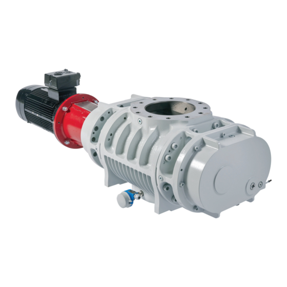
Roots pumps from the ATEX series are equipped with a magnetic coupling and a thermometer. Fig. 2: Structure of Okta 5400 ATEX | Okta 8100 ATEX 1 Measurement connection, vacuum side Valve for inert gas filling (mounted on the... -
Page 22: Mounting Orientations
● Input voltage range (motor rating plate) 3.3 Product features Pump type Nominal pumping speed Motor rated power Intake flange/direction of flow Okta 5400 ATEX 11 kW top/vertical 5420 – 8120 m Okta 8100 ATEX 5420 – 8120 m 18.5 kW top/vertical Tbl. -
Page 23: Transportation And Storage
Transportation and Storage 4 Transportation and Storage 4.1 Transporting vacuum pump DANGER Risk of explosion from electrostatic charging during transport There is a risk of fatalities when transporting packaging material (foil) and plastic containers in poten- tially explosive areas. Ignition can cause very serious injuries, and even fatalities. ►... -
Page 24: Storing Vacuum Pump
Transportation and Storage Fig. 3: Transporting vacuum pump 1 Lifting eyes Information for transport of the vacuum pump without packaging 1. Unpack the vacuum pump. 2. Attach a suitable lifting device to the lifting eyes in the bearing shields. 3. In addition, place a sling around the motor flange to keep it balanced. 4. -
Page 25: Installation
Installation 5 Installation 5.1 Preparatory work WARNING Risk of crushing from rotating parts Fingers and hands may be caught by rotating pistons within the connection flange. This results in se- vere injuries. ► Keep limbs out of the reach of the roots pump. Filling the nitrogen The vacuum pump is filled with nitrogen to protect against corrosion, therefore the suction chamber has a slight over pressure (200 hPa) upon delivery... -
Page 26: Setting Up Vacuum Pump
Installation 5.2 Setting up vacuum pump CAUTION Danger of burns on hot surfaces Depending on the operating and ambient conditions, the surface temperature of the vacuum pump can increase to above 70 °C. If access to the vacuum pump is unrestricted, there is a danger of burns due to contact with hot surfaces. -
Page 27: Filling With Lubricant
Installation Fig. 5: Permissible mounting orientation: Vertical direction of flow 5.4 Filling with lubricant NOTICE Property damage from using non-approved lubricant Attainment of product-specific performance data is not ensured. If non-approved lubricants are used, all liability and warranty claims against Pfeiffer Vacuum are excluded. ►... -
Page 28: Connecting Vacuum Side
Installation Fig. 6: Filling with lubricant 1 Filler screws Drain screw 2 Fill level limiter Filling the lubricant The oil chambers of the roots pump are each equipped with a fill level limiter. A riser tube limits the max. fill level. ●... -
Page 29: Tbl. 8: Maximum Permissible Forces And Torques On The Intake Flange
Installation NOTICE Property damage from intake of solid particles During commissioning, there is a risk of damage to the suction chamber from dirt from the system or the pipes. ► Use a suitable protective strainer ("start-up strainer") in the intake flange. ►... -
Page 30: Connecting Fore-Vacuum Side
Installation 5.6 Connecting fore-vacuum side WARNING Risk of crushing from rotating parts Fingers and hands may be caught by rotating pistons within the connection flange. This results in se- vere injuries. ► Keep limbs out of the reach of the roots pump. CAUTION Danger of injury from bursting as a result of high pressure in the exhaust line Faulty or inadequate exhaust pipes lead to dangerous situations, e.g. -
Page 31: Tbl. 9: Requirements On The Cooling Water Composition
Installation Parameter Cooling water Appearance ● filtered ● mechanically clear ● visually clear ● no turbidity ● no sediment ● free from grease and oil pH value 7 to 9 Carbonate hardness, max. 10 °dH 12.53 °e 17.8 °fH 178 ppm CaC0 Chloride content, max. -
Page 32: Setting And Checking Temperature Monitoring
Installation Fig. 8: Cooling water connections, in series 1 Cooling water inlet Return line 2 Dirt trap Cooling water outlet 3 Feed line Procedure Pfeiffer Vacuum recommends the use of a dirt trap in the supply line. 1. Connect the cooling water supply line to the hose nozzle of the quick fitting coupling at the desig- nated cooling water inlet. -
Page 33: Checking Thermometer Installation Dimension
Installation 5.8.1 Checking thermometer installation dimension Faulty temperature measurement Faulty temperature measurement due to deviating installation dimension. ● Measuring point: Center of outlet Required tools ● Open-end wrench, WAF 17 Fig. 9: Check temperature monitoring 1 Fore-vacuum flange Installation dimension 2 Thermometer Checking installation of thermometer ►... -
Page 34: Connecting To Mains Power Supply
Installation Procedure ► Set up the ignition protection system on the operator side in accordance with the requirements for the device category or EPL. ► Observe the necessary ignition protection system type. Regular check ► Check the thermometer regularly and compare the temperature with other process temperatures. ►... -
Page 35: Connecting Three Phase Motor With 6-Pin Terminal Board
Installation NOTICE Motor damage from overheating Limited motor fan cooling capacity, caused by low speeds, causes the motor to overheat. ► During operation with frequency converter, observe the rotation speed range specified in the technical data. The vacuum pumps are equipped with three-phase motors for different voltages and frequencies. The applicable motor type is shown on the motor rating plate. -
Page 36: Checking Direction Of Rotation
Installation 5.9.2 Checking direction of rotation Fig. 12: Check of direction of rotation Procedure When switching on for the first time, check the roots pump direction of rotation. 1. Switch the vacuum pump on briefly (2 to 3 seconds) – The motor and coupling must rotate clockwise (see directional arrow in the figure). 2. -
Page 37: Observing Motor Torque
● The piston is blocked due to deposits. ● The roots pump was switched on before the backing pump. Torque limitation of Okta 5400 ATEX | Okta 8100 ATEX Limit the torque with a soft starter (e.g., Siemens 3RW30, Eaton DS7) or a frequency con- verter. -
Page 38: Operation
Operation 6 Operation 6.1 Commissioning vacuum pump WARNING Danger of poisoning due to toxic process media escaping from the exhaust pipe During operation with no exhaust line, the vacuum pump allows exhaust gases and vapors to escape freely into the air. There is a risk of injury and fatality due to poisoning in processes with toxic process media. -
Page 39: Observe The Mechanical Resonance
Operation 6.2.2 Observe the mechanical resonance NOTICE Damage from mechanical resonance when operating with frequency converter The use of a frequency converter allows operation of the vacuum pump with variable speed ranges. Potentially critical speed ranges lead to increased frequencies and vibrations. Permanent operation in critical speed ranges impairs running behavior of the vacuum pump. -
Page 40: Performing Vibration Monitoring
Operation NOTICE Property damage from impermissibly high sealing gas pressure Excessive sealing gas pressure leads to damage to the seals after switching on the vacuum pump. ► Make sure that the sealing gas pressure inside the pump does not exceed 1200 hPa. ►... - Page 41 Operation Boundary conditions of the vibration measurement The boundary conditions of the vibration measurement (including the operating conditions, measurement parameters, etc.) and the equipment for vibration measurement (including the vibration sensors) must comply with the requirements of the following directives and standards.
-
Page 42: Monitoring Operating Condition
Operation Carrying out a bearing replacement 1. Carry out a bearing replacement (in accordance with Maintenance Level 3) if significant changes occur in the trend (significant rise or drop) in accordance with the guidelines VDI 3836 or VDI 3832 during condition monitoring of the vacuum pump or the pump bearing. 2. -
Page 43: Monitoring The Motor Condition
Operation Frequency Roots pump Rotation frequency (n) Hz Output frequency (4 × n) Hz Tooth engagement frequency (92 × n) Hz Harmonic (integral) multiples of these frequencies can also be of relevance to diagnostics Tbl. 15: Characteristic frequencies of the roots pump Evaluating vibration spectrum Pfeiffer Vacuum recommends using the envelope curve spectrum to ensure fast and relia- ble diagnostics in the event of bearing damage. - Page 44 Operation Procedure with clean processes You can switch off the vacuum pump in every pressure range, between atmospheric pressure and ulti- mate pressure directly after the process end. 1. Close the shut-off valve in the vacuum line and disconnect the vacuum pump from the process. 2.
-
Page 45: Maintenance
Maintenance 7 Maintenance 7.1 Maintenance information DANGER Risk of explosion when carrying out installation and maintenance work in potentially explo- sive areas There is a risk of explosion if unsuitable tools are used in potentially explosive areas. Ignition can cause very serious injuries. ►... -
Page 46: Checklist For Inspection And Maintenance
Maintenance NOTICE Damage from incorrect maintenance work Unprofessional work on the vacuum pump will lead to damage for which Pfeiffer Vacuum accepts no liability. ► Ensure that only the following categories of persons are authorized to perform servicing tasks: – Pfeiffer Vacuum employees with corresponding qualifications. –... -
Page 47: Changing Lubricant
Maintenance Action Inspec- Mainte- Mainte- Mainte- Required mate- tion nance nance nance rial level 1 level 2 level 3 described in document Not rel- evant Interval daily ≤ 1 year ≤ 3 years ● Checking vacuum pump for leaks ■ ●... -
Page 48: Draining Lubricant
Maintenance CAUTION Scalding from hot lubricant Danger of scalding when draining lubricant if it comes into contact with the skin. ► Wear protective equipment. ► Use a suitable collection receptacle. Pfeiffer Vacuum recommends determining the precise service life of the lubricant in the first operating year. -
Page 49: Filling With Lubricant
Maintenance 7.3.2 Filling with lubricant Required consumables ● Lubricant of the vacuum pump Required tools ● Allen key, WAF 8 ● Ring spanner, WAF 27 Fig. 16: Filling with lubricant 1 Filler screws Drain screws 2 Fill level limiter Filling with lubricant 1. - Page 50 Maintenance NOTICE Property damage from incorrect cleaning procedure Flushing fluid and process media that enters the bearing and oil chambers will stick. ► During the cleaning processes, always protect all bearings with sealing gas in order to prevent a contamination of the lubricant and bearing chambers. The clearance between pistons and housing are within a tenth of a centimeter range.
-
Page 51: Decommissioning
Decommissioning 8 Decommissioning 8.1 Shutting down for longer periods Before shutting down the vacuum pump, observe the following instructions to adequately protect the in- terior of the vacuum pump (suction chamber) from corrosion: Procedure for a longer downtime of the vacuum pump (> 1 year) 1. -
Page 52: Recycling And Disposal
Recycling and disposal 9 Recycling and disposal WARNING Health hazard through poisoning from toxic contaminated components or devices Toxic process media result in contamination of devices or parts of them. During maintenance work, there is a risk to health from contact with these poisonous substances. Illegal disposal of toxic sub- stances causes environmental damage. -
Page 53: Malfunctions
Malfunctions 10 Malfunctions WARNING Danger to life from electric shock in the event of a fault In the event of a fault, devices connected to the mains may be live. There is a danger to life from electric shock when making contact with live components. ►... -
Page 54: Tbl. 18: Troubleshooting
Malfunctions Problem Possible causes Remedy Unusual noises during ● Suction chamber dirty ● Switch off the roots pump immedi- operation ately. ● Clean suction chamber. ● Motor is running – vacuum ● Switch off the roots pump immedi- pump is not working, i.e., ately. -
Page 55: Service Solutions By Pfeiffer Vacuum
Service solutions by Pfeiffer Vacuum 11 Service solutions by Pfeiffer Vacuum We offer first-class service High vacuum component service life, in combination with low downtime, are clear expectations that you place on us. We meet your needs with efficient products and outstanding service. We are always focused on perfecting our core competence –... - Page 56 Service solutions by Pfeiffer Vacuum 5. Prepare the product for transport in accordance with the provisions in the contamination declaration. a) Neutralize the product with nitrogen or dry air. b) Seal all openings with blind flanges, so that they are airtight. c) Shrink-wrap the product in suitable protective foil.
-
Page 57: Spare Parts
Spare parts 12 Spare parts 12.1 Ordering spare parts packs Observe the following instructions when ordering spare parts: ► Have the vacuum pump part number, and any other necessary details from the rating plate, to hand when ordering spare parts. ► Install original spare parts only. 57/64... -
Page 58: Accessories
Accessories 13 Accessories View the line of accessories for Pfeiffer Vacuum roots pumps online at pfeiffer-vacuum.de. 13.1 Accessory information Fixing materials Type-specific assembled packages ensure secure fastening of the vacuum pump. Optionally with splint- er shield or protective screen. Display units and cable Display and operating units are used to check and adjust operating parameters. -
Page 59: Technical Data And Dimensions
● For deviations in special versions, please refer to the rating plates or the enclosed in- formation. 14.2 Technical data Type designation Okta 5400 ATEX Okta 8100 ATEX ATEX-certification Ex II 2/2G Ex h IIC T4...T2 Ex II 2/2G Ex h IIC T4...T2... -
Page 60: Substances In Contact With The Media
Technical data and dimensions Type designation Okta 5400 ATEX Okta 8100 ATEX Emission sound pressure level (EN ISO 74 dB(A) 74 dB(A) 2151) at intake pressure 1 hPa Motor coupling Magnet coupling Magnet coupling Motor seal Hermetic sealing Hermetic sealing... -
Page 61: Dimensions
Technical data and dimensions 14.4 Dimensions DN 250 PN 16 1787.4 M12 (4×) DN 250 PN 16 M 24×3 - 37/43 deep (12 ×) Fig. 17: Dimensions Okta 5400 ATEX | Okta 8100 ATEX Dimensions in mm 61/64... -
Page 62: Declaration Of Conformity
Declaration of Conformity Declaration for product(s) of the type: Roots pump Okta 5400 ATEX | Okta 8100 ATEX II 2/2G Ex h IIC T4 – T2 Gb X We hereby declare that the listed product satisfies all relevant provisions of the following European Directives. - Page 63 63/64...
Need help?
Do you have a question about the OKTA 5400 ATEX and is the answer not in the manual?
Questions and answers