Table of Contents
Advertisement
Quick Links
Advertisement
Table of Contents

Related Manuals for Preiffer HiPace 3400 MC

Summary of Contents for Preiffer HiPace 3400 MC
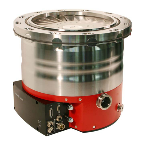
- Page 1 HiPace 3400 MC Turbopump Operating Instructions...
-
Page 2: Table Of Contents
4.13. Emergency Stop ...............17 4.14. Safety Bearings..............18 Understanding The 4.15. Monitoring Of The Balancing Condition....... 18 HiPace 3400 MC Pump .....4 2.1. Main Features..............4 4.16. Emergency Power Operation......... 18 Proper Use ................5 4.17. Shut Down For Longer Periods........18 Improper Use .............. -
Page 3: Safety Instructions
(please see Section 12. Accessories). ☞ The Turbopump HiPace 3400 MC and Magnetic Bearing Controller TM 3000 should never be separated. ☞ The unit has an IP 54 protection class. Appropriate Please note, important information about the... -
Page 4: Understanding The Hipace 3400 Mc Pump
2. Understanding The HiPace 3400 MC Pump Transportation 2.1. Main Features The protective cover on the high vacuum flange The Turbopump HiPace 3400 MC constitutes a complete unit CAUTION locks the rotor to protect the safety bearings with the Electronic Drive Unit and Magnetic Bearing Control- during transportation. -
Page 5: Proper Use
– Installation of the pumps in systems where the turbomole- Proper Use cular pumps are subjected to impact-like stress and vibra- – The Turbopump HiPace 3400 MC may only be used to tions or the effect of periodically occurring forces. generate a vacuum. -
Page 6: Installation
3. Installation 3.1. Preparations For Installation To reliably prevent the pump from twisting if the WARNING rotor suddenly blocks, it is absolutely prohibited Do not carry out any unauthorised conversions to secure a pump on a vacuum chamber with WARNING or alterations to the turbopump. -
Page 7: Earthquake Safety
Earthquake Safety Installation is done as follows: An earthquake can result in contact with the safety bearings; ISO-F to an ISO-F flange see Section 4.14. All forces occurring thereby are safely absorbed by the previously described flange connections. M12 hexagon screws used must meet the stan- ACHTUNG The vacuum chamber, in turn, must be secured against dards I I S S O O 4 4 0 0 1 1 7 7 (DIN 933). -
Page 8: Connecting The Fore-Vacuum Side
For more detailed information about the fore-vacuum pump relay box and its installation, see Operating Instructions PT 0030 BN. 3.4. Connecting The Cooling The Turbopump HiPace 3400 MC must be operated with water cooling. For cooling water connections, see Section 11.1. Dimension Diagram) Water cooling Cooling water either –... -
Page 9: Electronic Drive Unit And Magnetic Bearing Controller Tm 3000
3.5. Electronic Drive Unit And Magnetic Bearing Controller TM 3000 General Unit Description The Electronic Drive Unit And Magnetic Bearing Controller TM 3000 is always used in combination with the turbopump and form a single unit. All functions necessary to operate the turbopump are preprogrammed on delivery. -
Page 10: Connecting The Tm 3000 To The Power Supply Tps 1400/1401
Connecting The TM 3000 To The Power 3.6. Connecting The Venting Valve and Supply TPS 1400/1401 Sealing Gas Valve Make sure that the power supply is completely The venting valve and the sealing gas valve form a single unit. WARNING They are a standard component of the turbopump and they disconnected from the mains during electrical are delivered already mounted and connected . -
Page 11: Plug Arrangement Remote
Plug Arrangement REMOTE P P i i n n D D e e s s c c r r i i p p t t i i o o n n / / E E x x p p l l a a n n a a t t i i o o n n F F u u n n c c t t i i o o n n T T y y p p e e + 24 V DC... -
Page 12: Connecting The Serial Interface Rs-485
3.8. Connecting The Serial Interface. An RS-232 (e.g. PC) can be connected via a PLEASE NOTE TIC 001 level converter (see Section 12. Using A DCU Or HPU Accessories). Electrical Connection The “RS-485” connection on the TM 3000 can be used to con- nect an operating component (DCU 002 o o r r HPU 001) with a screened 5-pin connecting cable in a point to point connec- Bus Operation Via RS-485 Interface... -
Page 13: Connection Diagram
3.9. Connection Diagram REMOTE potential free contacts electrically insulated optically insulated Optional slot DC Input RS485 SERVICE 140 VDC... -
Page 14: Operations
Magnetic bearings are non-wearing but have limited load capacity. Therefore, the HiPace 3400 MC is equipped with dry The following i i m m p p o o r r t t a a n n t t factory settings are programmed on... -
Page 15: Normal Operation Of The Turbopump
4.9. Rotation Speed Set Mode 4.5. Normal Operation Of The Turbopump The rotation speed set mode is selected if the gas throughput of the turbopump is to be modified. The pressure ratio and The turbopump is started up with maximum drive power. pumping speed of the pump fall with the rotation speed. -
Page 16: Gas Type Dependent Operation
4.11. Gas Type Dependent Operation Gas type characteristics lines “Gas Mode 1” With high gas loads and high rotation speeds, gas friction Ratation speed 400 Hz, causes the rotor to heat up. To prevent overheating, a power- cooling water flow rate 100 l/h rotation speed characteristic is implemented in the TM 3000, 3300 which allows the pump to be operated at any rotation speed... -
Page 17: Switching Off And Venting
CAUTION the axial bearing and require use of the safety bearing. The HiPace 3400 MC can only be vented using the pre-mounted venting valve. This cannot be ➡ Close the water supply. replaced by other venting equipment. -
Page 18: Safety Bearings
4.14. Safety Bearings 4.16. Emergency Power Operation During strong external vibrations or improper operation, the If the power supply fails during operation of the turbopump, rotor is supported by dry running safety bearings (see also the pump motor works as a generator and supplies the power Section 4.1.). -
Page 19: Remote Control Operation
4.18. Remote Control Operation The following functions are activated with “SPS High Level” and deactivated with “SPS Low Level”: If power failure occurs during operation, the CAUTION turbopump automatically restarts once power – Motor TMP ON/OFF returns. – Heating ON/OFF –... -
Page 20: Venting Modes
➡ Select «0 0 5 5 5 5 : : C C o o n n f f A A O O 1 1 » 4.19. Venting Modes ➡ Select function «0 0 », «1 1 » or «2 2 »: Venting is only possible after turning off the pumping station. -
Page 21: Error Messages And Warnings
5. Error Messages And Warnings Error messages and warnings can only be PLEASE NOTE displayed by the Display And Operating Units DCU 002 or HPU 001. 5.1. Error Messages / Status Messages Errors (”E E x x x x x x “) will always switch off the turbo- CAUTION pump and the connected components. -
Page 22: Warnings
5.2. Warnings Warnings (”Warning F F x x x x x x “) are indicative of functional restrictions or indicate the following faults. Components may be switched off. Number Description Explanation/troubleshooting F001 TMS warm-up time has elapsed Check heating cartridges; check TMS F002 TMS temperature limit has been reached Check cooling arrangement;... -
Page 23: Parameters
6. Parameters 6.1. General All turbopump or electronic drive unit and magnetic bearing controller variables relevant for its functioning are available in the form of parameters in the TM 3000. Each parameter has a number and a description, e.g. « « 0 0 2 2 6 6 : : O O p p M M o o d d e e T T M M P P » » . Factory settings can be retained or you can create your own settings under “Control Commands”... -
Page 24: Status Requests
6.3. Status Requests (readable only) Display Name, Description Unit Factory RS-485 Data type 2) setting Rem ctrld “REMOTE” function active Swpnt att Rotation speed switch point reached Error code Current error code Drv ovtemp Excess electronics temperature – TMP ovtemp Excess pump temperature Rotspd Att Set rotation speed reached (±... -
Page 25: Set Points
6.4. Set Points (readable and writable) Display Name, Description Unit Factory RS-485 Data type 2) setting TMP RUTime Maximum permissible run-up time Switch pnt < Rotation speed switch point TMSheatset TMS thermal temperature setpoint °C TMProt set Rotation speed setpoint in rotation speed control mode 50.0 100.0... -
Page 26: Monitoring The Operating Conditions
7. Monitoring The Operating Conditions 7.1. Operating Mode Display Via LED You can read off specific operating conditions of the turbopump and TM 3000 using three LEDs in the front plate of the TM 3000. The following operating conditions are displayed: L L E E D D C C o o n n t t i i n n u u o o u u s s l l y y O O N N C C o o n n t t i i n n u u o o u u s s l l y y O O N N... -
Page 27: What To Do In Case Of Breakdowns
8. What To Do In Case Of Breakdowns? Problem Possible causes Remedy Pump does not start; • Power supply interrupted • Check plug contact on the power supply None of the internal LEDs • Check the power supply line on the TM 3000 are lit •... -
Page 28: Service
9. Service Do make use of our service facilities Fill out the service request and the declaration on In the event that repairs are necessary a number of options contamination ➡ Download the forms “Service Request” and “Declaration are available to you to ensure any system down time is kept to a minimum: on Contamination”. -
Page 29: Maintenance
10. Maintenance We accept no liability for personal or material PLEASE NOTE damages or interruptions to operation resulting from improper maintenance, and all liability and guarantee claims are rendered void. Please contact your Pfeiffer Vacuum service location for all maintenance or reconditioning. Do not exert any mechanical load on the CAUTION Electronic Drive Unit and Magnetic Bearing... -
Page 30: Technical Data
11. Technical Data Size Unit HiPace 3400 MC Connection nominal diameter Inlet DN 320 ISO-F Outlet DN 40 ISO-KF Venting/Sealing gas connection DN 10 ISO-KF Nominal rotation speed 1/min / Hz 24,000 / 400 Standby rotation speed 1/min / Hz... -
Page 31: Dimensions
11.1. Dimensions Watercooling DN 40 ISO-KF / M44x1 G1/4" DN 10 ISO-KF / G1/8" Ø13,5 (12x) Ø DN 320 ISO-F Ø 425 Ø 318 COG = Center of gravity... -
Page 32: Accessories
12. Accessories D D e e s s c c r r i i p p t t i i o o n n S S i i z z e e N N u u m m b b e e r r N N o o t t e e / / c c o o r r r r e e s s p p o o n n d d i i n n g g O O r r d d e e r r A A m m o o u u n n t t o o p p e e r r a a t t i i n n g g i i n n s s t t r r u u c c t t i i o o n n s s... -
Page 33: Declaration Of Conformity
Compatibility" 2004/108/EC . The agent responsible for compiling the technical documentation is Mr. Jörg Stanzel, Pfeiffer Vacuum GmbH, Berliner Straße 43, 35614 Aßlar. HiPace 3400 MC Guidelines, harmonised standards and national standards and specifications which have been applied: DIN EN ISO 12100 : 2011-03... -
Page 34: Www.pfeiffer-Vacuum.com
Vacuum solutions Pfeiffer Vacuum stands for innovative and custom from a single source vacuum solutions worldwide, technological perfection, competent advice and reliable service. Complete range From a single component to complex systems: of products We are the only supplier of vacuum technology that provides a complete product portfolio.
Need help?
Do you have a question about the HiPace 3400 MC and is the answer not in the manual?
Questions and answers