Table of Contents
Advertisement
Quick Links
V20.2 UPDATES ............................................... 3
1. Introduction .......................................................... 6
1.1 System Features ............................................ 6
2. Choosing the installation location .................... 9
3. Installation .......................................................... 10
3.1 LED indicators and connections ................ 10
3.2 Inserting the Battery .................................... 11
3.3 WP8360 connections ................................... 12
3.4 GSM connection and configuration ........... 13
3.5 SIM card insertion ........................................ 13
3.6 WP8360 prerequisites ................................. 13
3.8 Panel reset .................................................... 14
3.9 Factory default restore ................................ 14
4. Programming ..................................................... 15
4.1 General guidance ......................................... 15
4.1.1 WP8360 panel indicators and controls ....... 16
4.1.2 Feedback sounds ....................................... 17
menu option ....................................................... 17
Permit is enabled ................................................. 17
4.2.2 Selecting options ........................................ 18
4.2.3 Exiting the installer mode ........................... 18
4.3 Setting installer codes ................................ 18
............................................................................. 19
4.4 Zones and devices ....................................... 19
options ................................................................. 19
4.4.2 Adding new wireless devices ...................... 20
Enrolling a Wired Input ..................................... 21
4.4.3 Deleting a device ........................................ 25
4.4.4 Modifying or reviewing a device ................. 25
4.4.5 Replacing a device ..................................... 26
4.4.6 Configuring soak test mode ........................ 27
settings ................................................................. 27
............................................................................. 28
4.5 Control panel ................................................ 29
D-308259 WP8360 Installation Guide
WP8360
Installation Guide
V20.2
Table of Contents
& menu options ................................................... 29
procedures .......................................................... 30
4.5.3 Configuring zones ...................................... 31
4.5.4 Configuring alarms and troubles ................ 32
4.5.5 Configuring siren functionality .................... 33
............................................................................ 33
4.5.7
(missing device) .................................................. 34
4.5.8 Configuring miscellaneous features........... 35
4.6 Communication ........................................... 36
& menu options .................................................... 36
connection ........................................................... 37
stations ................................................................ 39
............................................................................ 43
verification ........................................................... 43
programming access permissions ...................... 44
4.6.7 Broadband ................................................. 45
4.6.8 Wi-Fi .......................................................... 46
4.7 PGM Output ..................................................... 47
4.7.1 General guidance ..................................... 47
4.7.2 PGM output configuration ...................... 47
4.7.3 Entering Daytime Limits .......................... 48
4.8 Custom names ............................................ 48
4.8.1 Custom zone names .................................. 48
4.9 Diagnostics .................................................. 50
menu options....................................................... 50
4.9.2 Testing wireless devices ............................ 50
4.9.3 Testing the GSM module ........................... 52
4.9.4 Testing the SIM number ............................ 53
4.9.6 Testing the WLAN Module ......................... 54
4.10 User settings ............................................. 55
supervision
1
Advertisement
Table of Contents

Subscribe to Our Youtube Channel
Related Manuals for Tyco WP8360


Summary of Contents for Tyco WP8360
-
Page 1: Table Of Contents
4.6.2 Configuring GSM-GPRS (IP) - SMS cellular connection ............37 4.1 General guidance ......... 15 4.6.3 Configuring event reporting to monitoring 4.1.1 WP8360 panel indicators and controls ..16 stations ..............39 4.1.2 Feedback sounds ........17 4.6.4 Configuring event reporting to private users 4.2 Entering Installer Mode and selecting a... - Page 2 G3. Arming the system by Sabbath clock ..83 Adding a panel ............. 73 APPENDIX H. Glossary ........84 APPENDIX C. Specifications ........ 75 APPENDIX I. Compliance with standards .... 86 WP8360 Quick user guide ........91 C1. Functional ............ 75 D-308259 WP8360 Installation Guide...
-
Page 3: V20.2 Updates
The screen saver option - when activated - replaces the status display on the control panel 56:SCREEN SAVER with the words “SECURITY SYSTEM” if no key is pressed for more than 30 seconds. With partition disabled D-308259 WP8360 Installation Guide... - Page 4 When the procedure is complete, press to return to the home screen. Note: After you exit from the installer mode, all PGM outputs are turned off Options: disabled (default); turn ON; turn OFF; activate PULSE; toggle D-308259 WP8360 Installation Guide...
- Page 5 Use this configuration to define whether sirens enrolled in the zone are activated following an event. Select Enable to activate sirens on the zone. ACTIVATE SIRENS Select Disable to prevent sirens from being activated on the zone. Options: Disable (default); and Enable D-308259 WP8360 Installation Guide...
-
Page 6: Introduction
The WP8360 security system is accessible to home and property owners through their mobile devices. Installers program and configure the system remotely through the through the AlarmInstall application (see APPENDIX This manual refers to WP8360 v18 and above. The most updated manuals can be downloaded from the DSC Web site http://www.dsc.com. 1.1 System Features The following table lists the WP8360 features with a description of each feature and how to use it. - Page 7 Installation Instructions. flood. To configure notifications to Private Reporting to private The WP8360 system can be programmed to phones: refer to section 4.6.4 Configuring users and/or send notifications of alarm and other events monitoring station by...
- Page 8 Setting Installer Codes. only (PGx945) Arming Key External system can control arming and Refer to the WK241 and WK160 Installation disarming of the system. Instructions. GPRS usage The installer can define GPRS usage of third-party home automation application. D-308259 WP8360 Installation Guide...
-
Page 9: Choosing The Installation Location
2. Choosing the installation location To ensure the best possible mounting location for the WP8360 control panel, the following points should be observed when selecting a location: • Place approximately in the center of the installation site between all the transmitters, preferably in a hidden location. -
Page 10: Installation
Wi-Fi activation and deactivation K. Opening for reset button L. Restore to factory default settings: Press for 30 sec. to restore system parameters to factory defaults. M. Micro SD memory card holder (for future use) N. Enroll LED D-308259 WP8360 Installation Guide... -
Page 11: Inserting The Battery
3. To close the battery cover, align the two tabs of the battery cover with their respective slots and press down on the cover in the direction shown until a click is heard. D-308259 WP8360 Installation Guide... -
Page 12: Wp8360 Connections
Configurator software can be downloaded from www.visonic.com website if you are a registered user. After completing the setup in the configurator, disconnect the USB cable from the WP8360. Note: For details about installing and configuring the AlarmInstall Application, see APPENDIX A. -
Page 13: Gsm Connection And Configuration
GSM modem auto detection is activated after reset that is after power-up or after exiting the Installer Mode menu. This action causes the WP8360 to automatically scan the GSM COM ports for the presence of a GSM modem. In the event that the GSM modem auto detection fails and the modem was previously enrolled in the control panel, the message Cel Remvd Cnfrm is displayed on the Configurator’s Virtual Keypad. -
Page 14: Panel Reset
2. The green LED blinks 3 times and a success beep is emitted. The panel immediately initiates a software reset. Note: If the default restore is not successful, the red LED light remains on for 3 seconds and a failure beep is emitted. D-308259 WP8360 Installation Guide... -
Page 15: Programming
Tech Tip For your convenience, program the WP8360 on a work bench before the installation. You can obtain operating power from the backup battery or from the AC/DC adapter. ATTENTION! FIRST SWITCH ON THE CONTROL PANEL and then INSERT BATTERIES INTO ACCESSORIES DEVICES. -
Page 16: Wp8360 Panel Indicators And Controls
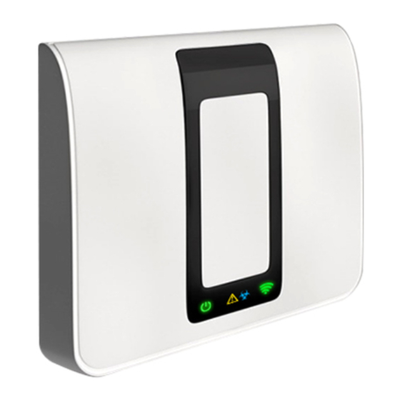
4.1.1 WP8360 panel indicators and controls LED indicators Figure 4.1 Indicators Function Power (Green) indicates that your system is connected to the power outlet. Arming status (Flashing Red / Static Red) indicates HOME / AWAY. Trouble condition (TRBL) (Orange) lights when the system detects an abnormal condition caused by a fault. -
Page 17: Feedback Sounds
(see also [1] in Step 1 above). To configure the panel to comply with user permission requirements - see option #91 User Permit in section 4.5.8. D-308259 WP8360 Installation Guide... -
Page 18: Selecting Options
Defining specific communication parameters – see 3:C.S REPORTING in sections 4.6.2 and 4.6.3. • Resetting the WP8360 parameters to the default parameters – see 09:FACTORY DEFLT in section 4.11. Note: Not every system includes a Master Installer code feature. In such systems, the Installer can access all Installer Mode menu and sub-menu options identical to the Master Installer. -
Page 19: Identical Installer And Master Installer Codes
To replace faulty devices with automatic configuration of the new device. 4.4.5 REPLACE DEVICES ADD TO SOAK TEST To enable the Soak Test for device zones. 4.4.6 DEFINE DEFAULTS To customize the defaults of the device's parameters according to your personal 4.4.7 D-308259 WP8360 Installation Guide... -
Page 20: Adding New Wireless Devices
ID numbers into the panel and complete the device configuration. This can be done from a remote location using the AlarmInstall app. Following the 1 stage, the WP8360 panel waits for the device to appear on the network in order to complete the enrollment. -
Page 21: Enrolling A Wired Input
Press the enroll button for 2-5 seconds until the LED lights steadily and then release the button. The LED will extinguish or may blink for a few more seconds until the enrollment is completed. If enrollment is successfully completed, the WP8360 sounds the Success Tune and the Virtual Keypad momentarily shows DEVICE ENROLLED and then reads the device details. - Page 22 Instructions. The defaults of the device parameters can be also configured as explained in section 4.4.7. [11] After completing the configuration of the device, the wizard brings you to the Next Step menu with the following 3 options: D-308259 WP8360 Installation Guide...
- Page 23 This zone does not create an alarm and is often used for non-alarm applications. For example, a detector used only for sounding a chime. A Fire zone is used for connecting the PGX945 (magnetic contact with hard-wired input) to a Fire D-308259 WP8360 Installation Guide...
- Page 24 Monitoring Station (and does not depend on the Abort Time). Notes: 1. Opening/closing the Guard keybox causes the WP8360 to signal the Monitoring Station. 2. Operates with the magnetic contact device with auxiliary input. A zone for outdoor areas where an activated alarm does not indicate intrusion into the house.
-
Page 25: Deleting A Device
From here on the process is same as the configuration process that follows the enrollment of that device. To continue, refer to Section 4.4.2 Adding a New Wireless Device Part B. When done, the display will show the next device of the same type (i.e. Motion camera). D-308259 WP8360 Installation Guide... -
Page 26: Replacing A Device
Scroll the Device Group, identify (by zone and/or ID number) the exact device you require to replace, for example: K03: Keyfob > ID No. 300-0307. If you try to enroll a new device of a different type than the replaced device, the WP8360 will reject the new device and the Virtual Keypad display will read WRONG DEV.TYPE. -
Page 27: Configuring Soak Test Mode
4.4.7 Defining configuration defaults for device settings WP8360 enables you to define the default parameters used during enrollment and to change them whenever you require so that new devices enrolled into the system will be configured automatically with these default parameters without the need to modify the configuration of each new enrolled device. -
Page 28: Updating Devices After Exiting Installer Mode
4.4.8 Updating devices after exiting Installer Mode When exiting the Installer Mode, the WP8360 panel communicates with all devices in the system and updates them with the changes that have been performed in their Device Settings configuration. During the updating period, the display indicates DEV UPDATING 018 where the number (for example, 018) is a countdown of the remaining number of devices yet to be updated. -
Page 29: Control Panel
Behavior Supervision 21:SWINGER STOP 61:JAM DETECT When 22:CROSS ZONING 44:SIREN TIME 62:MISSING REPRT done to Step 2 45:STROBE TIME 63:NOT READY 64:MISS/JAM ALRM 65:SMOK FAST MIS Miscellaneous 4.5.8 80:3 PARTY H.A 91:USER PERMIT 93:SOAK PERIOD D-308259 WP8360 Installation Guide... -
Page 30: Configuring Arming/Disarming And Exit/Entry Procedures
Options: normal (default); restrt+arm home; restart>reentry and end by exit. Note: In some WP8360 variants, this menu is displayed in the Operation Mode only (see section 4.14). Define whether or not the user will be allowed to perform quick arming or not. Once quick 05:QUICK ARM arming is permitted, the control panel does not request a user code before it arms the system. -
Page 31: Configuring Zones
D: During entry delay, the system can be disarmed using keyfobs or by code using the Configuration device (PC or mobile) (on entry all.). Note: In some WP8360 variants, this menu is displayed in the Operation Mode only (see section 4.14). -
Page 32: Configuring Alarms And Troubles
4.14). 37:ABORT TIME The WP8360 can be configured to provide a delay before reporting an alarm to the Monitoring Station (not applicable to alarms from 24H SILENT and EMERGENCY zones). During this delay period, the siren sounds but the alarm is not reported. If the user disarms the system within the delay time, the alarm is aborted. -
Page 33: Configuring Siren Functionality
Note: This feature is not applicable in the USA. 40:ABORT FIRE T. Select the length of time allowed by the system to abort a Fire alarm. The WP8360 is able to provide an abort interval that starts upon detection of a Fire event. During this interval, the buzzer sounds a warning but the siren remains inactive and the alarm is not reported. -
Page 34: Configuring Jamming And (Missing Device)
61:JAM DETECT detected and reported or not. If any of the jam detection options is selected, the system will not allow arming under jamming conditions. The WP8360 provides several jam detect and reporting options to comply with the following standards: Note: Jamming is identified by the message system jammed displayed on the Virtual Keypad. -
Page 35: Configuring Miscellaneous Features
2. If a change is made to the period of time of the Soak Test while the zone is currently being tested, this will restart the Soak Test. 3. The start of the Soak Test period is defined in the factory from 9 AM (09:00). D-308259 WP8360 Installation Guide... -
Page 36: Communication
The COMMUNICATION menu enables you to configure and customize the communication and reporting of alarm, troubles and other system events for monitoring companies or private users according to your local requirements and personal preferences. WP8360 offers a variety of communication means including Cellular GSM, GPRS, EMAIL, MMS or SMS and IP via broadband internet connection. -
Page 37: Configuring Gsm-Gprs (Ip) - Sms Cellular Connection
SMS Channel. For further information, see section 4.6.3 options 26 & 27. Options: disable (default); enable. GPRS APN Enter the name of the APN Access Point used for the internet settings for the GPRS The name of the product is PowerLink3 IP Communicator D-308259 WP8360 Installation Guide... - Page 38 GSM call every 28 days sending a test message either to the first SMS number (if exists) or alternatively first private telephone number. Options: Disable (default) or Every 28 days. TRANS. PROTOCOL Select the IP protocol used to transfer data over the internet/GPRS. Options: TCP (default); or UDP. D-308259 WP8360 Installation Guide...
-
Page 39: Configuring Event Reporting To Monitoring Stations
4.6.3 Configuring event reporting to monitoring stations The WP8360 control panel is designed to report alarm, alerts, troubles and other events and messages to two Monitoring Stations C.S.1 and C.S.2 via Cellular i.e. GPRS (IP) & SMS or Broadband IP communications channels. In... - Page 40 Options: 2 attempts; 4 attempts (default); 8 attempts; 12 attempts and 16 attempts. 51: AUTO-TST LOOP To verify a proper communication channel, the WP8360 can be configured to send a test event to the Monitoring Station periodically. You can set the interval between the consecutive test events or disable the automatic sending of this event entirely.
- Page 41 Options: report enabled (default) and report disabled 64:SYST.INACTIVE The WP8360 can report a System Inactive event message (CID event 654) to the Monitoring Station if the system is not used (armed) during a predefined time period. Options: report disabled (default); after 7/14/30/90 days.
- Page 42 Note: Alarms group has the highest priority and Alerts group has the lowest priority. The WP8360 allows you also to select which event groups will be reported to each of the two Monitoring Stations. The table below describes the available reporting options. The minus (-) symbol means "but/less/except" e.g. all(-alrt) means all events except alerts.
-
Page 43: Configuring Event Reporting To Private Users
4.6.4 Configuring event reporting to private users The WP8360 system can be programmed to send various SMS event notifications such as alarm, arming or trouble events, if a GSM option is installed. The system can send the messages also to 4 emails, MMS and SMS telephone numbers via the server. -
Page 44: Configuring Upload / Download Remote Programming Access Permissions
4.6.6 Configuring upload / download remote programming access permissions Using a PC, the WP8360 can be configured (by upload/download) either locally or from remote via GPRS cellular communication. Local programming can be performed by directly connecting the computer to the panel's USB port using the Configurator software or AlarmInstall app in Direct Mode. -
Page 45: Broadband
→ Panel SIM Tel.# Enter the WP8360 SIM card telephone number. The PowerManage server at the Monitoring Station sends an SMS or voice message to this number for the panel to call back the (Previously known as "My SIM Tel.#") PowerManage server via GPRS for initiating the uploading / downloading process. -
Page 46: Wi-Fi
Press to return. To close the access-point channel, from the ACCESS-POINT menu, select STOP 8: WiFi > ACCESS-POINT > A.POINT. STOP A.POINT The panel shows the status when you close the access-point channel. Press to return. D-308259 WP8360 Installation Guide... -
Page 47: Pgm Output
Determine the PGM by one of the following options: Disable (default) PGM: BY OTHER ON by Com Fail: The PGM output is activated when the panel fails to report an event. ON by Siren: The PGM output is activated by an external wired siren. D-308259 WP8360 Installation Guide... -
Page 48: Entering Daytime Limits
Master Bdrm. To change the name, at the blinking cursor, enter the Location name you require and at the end, press to confirm. When done, press to return. Note: To enter the Location name use the String Editor below. IMPORTANT! The editing of a custom zone name automatically deletes the original text. D-308259 WP8360 Installation Guide... - Page 49 Exiting the edit screen and moves one level up to previous or top menu without saving the edit string. Exiting the edit screen and moves to the <OK> TO EXIT screen without saving the edit string. D-308259 WP8360 Installation Guide...
-
Page 50: Diagnostics
Unit is OK 4.9.2 Testing wireless devices The WP8360 enables to test the wireless devices attached to the panel. You can test all devices, one device at a time, display devices' status, and review any RF problems. ... - Page 51 NOW communication test failed); NOT TST (results are shown without any performed test); NOT NET [device is not networked (not fully enrolled)]; NONE (keyfob 24Hr result); or EARLY (result of the last 24Hrs without D-308259 WP8360 Installation Guide...
-
Page 52: Testing The Gsm Module
Please wait… 07:DIAGNOSTICS GSM/GPRS Enter the GSM/GPRS menu, and press to initiate the GSM diagnostic test. Upon test completion, the WP8360 will present the test result. The following table presents the test result messages. Message Description Unit is OK GSM / GPRS is functioning correctly GSM comm. -
Page 53: Testing The Sim Number
Connect srvr. Test is in progress waiting for connection to the server Request SMS Test is in progress requesting server to send SMS Wait for SMS Test is in progress waiting to receive SMS from server D-308259 WP8360 Installation Guide... -
Page 54: Testing The Broadband/Powerlink Module
4 min. before it is displayed. 2. If the Broadband Module is not registered to the WP8360, the menu BROADBAND MODULE will not be displayed. The following table presents the list of messages that may be reported:... -
Page 55: User Settings
9 – “Eth. connected” Ethernet connection detected 4.10 User settings The USER SETTINGS menu provides you with a gateway to the user settings through the regular user menus. Refer to the WP8360 User's Guide for detailed procedures. D-308259 WP8360 Installation Guide... -
Page 56: Factory Default
4.11 Factory default The FACTORY DEFLT menu enables you to reset the WP8360 parameters to the factory default parameters. To obtain the relevant parameters defaults, contact the WP8360 dealer. Reset factory default parameters as follows: Step 1 Step 2 Step 3... -
Page 57: Partitioning
To enable or disable the partition feature, proceed as follows: Step 3 Step 4 Step 1 Step 2 Partitions are Select 12:PARTITIONING menu Select whether to Enable or Disable now enabled Partitions ◼ ◼ to Step 1 Disable Enable 12:PARTITIONING Enable D-308259 WP8360 Installation Guide... -
Page 58: Operation Mode
4.14 Operation mode Note: The Operation Mode feature is applicable only in specific WP8360 variants. 4.14.1 General guidance – Operation mode menu This mode allows you to select an operation mode for the control panel according to specific compliance standards. -
Page 59: Dd243 Setup
3/4 minutes 10:ABORT TIME The WP8360 can be configured to provide a delay before reporting an alarm to the Monitoring Station (not applicable to alarms from FIRE, 24H SILENT and EMERGENCY zones). During this delay period, the siren sounds but the alarm is not reported. If the user disarms the system within the delay time, the alarm is aborted. - Page 60 10:ABORT TIME The WP8360 can be configured to provide a delay before reporting an alarm to the monitoring station (not applicable to alarms from FIRE, 24H SILENT and EMERGENCY zones). During this delay period, the siren sounds but the alarm is not reported. If the user disarms the system within the delay time, the alarm is aborted.
-
Page 61: Cp01 Setup
Options: 30 (default)/45/60 seconds; 3/4 minutes 10:ABORT TIME The WP8360 can be configured to provide a delay before reporting an alarm to the monitoring station (not applicable to alarms from FIRE, 24H SILENT, EMERGENCY, GAS FLOOD and TEMPERATURE zones). During this delay period, the external siren will not sound and the alarm is not reported. -
Page 62: Other Setup
Options : 00/15 (ENTRY DELAY 2 default)/30 (ENTRY DELAY 1 default)/45/60 seconds; 3/4 minutes The WP8360 can be configured to provide a delay before reporting an alarm to the monitoring 10:ABORT TIME station (not applicable to alarms from FIRE, 24H SILENT and EMERGENCY zones). During... - Page 63 Time interval. Options: in 00 (default in USA)/15/30(default)/45/60 seconds; in 2/3/4 minutes The WP8360 can be configured to provide a Cancel Alarm time window that starts upon 11:CANCEL ALARM reporting an alarm to the Monitoring Station. If the user disarms the system within that cancel alarm time, a cancel alarm message is sent to the Monitoring Station indicating that the alarm was cancelled by the user.
-
Page 64: Periodic Test
The first siren enrolled in the panel sounds for 3 seconds after which the WP8360 system will automatically repeat the procedure for the next siren enrolled in the system until all sirens are tested. - Page 65 Walk throughout the site to test the detectors / sensors or press any key of the selected handheld device to initiate the test. During testing, you can also check the signal strength indication of each device, (for further D-308259 WP8360 Installation Guide...
- Page 66 Activate the input of the detector; the following screens will appear: <Zxx IS <OK> SEND IMAGE. ACTIVATE> E-MAIL TEST To test emails, proceed as follows: Depending on shock detector model, one of the following may appear instead: "Zxx:Shk+AX" / " Zxx:Shk+CntG3" /" Zxx:Shk+CntG2". D-308259 WP8360 Installation Guide...
- Page 67 2. Since a Burglary alarm is sent, an alarm event must be configured for reporting events (see sections 4.6.3 Configuring Events Reporting to Monitoring Stations and 4.6.4 Configuring Events Reporting to Private Users). D-308259 WP8360 Installation Guide...
-
Page 68: Maintenance
Use also RF diagnostics to check signal strength. • Lift the telephone receiver and make sure a LINE FAILURE There is a problem with the telephone line telephone line can be heard • Check the telephone connection to the control panel D-308259 WP8360 Installation Guide... - Page 69 Detector alarms when in Soak Test mode If you wish to continue the Soak Test, no further action should be taken. If you wish to abort the Soak Test, disable the Soak Test (see section 4.4.6). D-308259 WP8360 Installation Guide...
-
Page 70: Replacing The Backup Battery
Replacement and first-time insertion of battery pack is similar, see Figure 3.2. Separate the panel from the base, see section 3.2 Installing the WP8360 battery and cables for details. After inserting the new battery pack correctly, return the panel to the base and place the screw in the locked position. The TROUBLE indicator is extinguished. -
Page 71: Reading The Event Log
The system erases the event log Press to revert to normal operating mode. Clicking the button repeatedly at any stage in the procedure takes you one level up with each click. Clicking the button will take you to <OK> TO EXIT. D-308259 WP8360 Installation Guide... -
Page 72: Appendix A. Working With The Alarminstall Application
APPENDIX A. Working with the AlarmInstall Application The AlarmInstall mobile application is used by installers to configure the WP8360 security system and provides an easy-to-use Virtual or Touch Keypad that allows you to fully control the panel configurations. Installing the AlarmInstall application Note: The AlarmInstall App can be installed on Apple or Android devices. -
Page 73: Adding A Panel
Panel icons and keys Icons show the status of the WP8360. Use the control keys to move through the menu items of the panel and the arming keys to arm or disarm the system. Other keys are designated for certain tasks for example to review event logs. - Page 74 DISARM / OFF: Disarming the system and stopping alarms Other Keys Function Chime ON/OFF Reviewing the event log Emergency Fire Panic Note: The above buttons are identical in function to the corresponding buttons shown throughout the document. D-308259 WP8360 Installation Guide...
-
Page 75: Appendix C. Specifications
850, 900, 1800, 1900 , 900 , 1900 , 2100 Z-Wave (MHz) (optional) 868.4, 908.4, 921.4 WiFi - optional 2.4 GHz. Access Point is for IP camera support only Covered by Module 2 Covered by Module 1 D-308259 WP8360 Installation Guide... -
Page 76: C3. Electrical
Operating Temp. Range 32°F to 120°F (0°C to 49°C) Storage Temp. Range 50°F to 122°F (10°C to 50°C) Humidity 93% relative humidity, @ 30°C (86°F) Size 158x114.5x36.5 mm (6.22x4.5x1.43 in.) Weight 225g (8 Oz) Color White D-308259 WP8360 Installation Guide... -
Page 77: C6. Peripherals And Accessory Devices
PowerManage server only the first 10 clips received from the cameras. Smoke Detector: PGx936 Keyfob: PGx939, PGx929 Keypad: WK241, WK160 Indoor Siren: PGx901 Outdoor Sirens: PGx911 Repeater: PGx920 Gas: PGx913 (CO detector) Glass-break: PGx922 Temperature: PGx905 Flood: PGx985 Shock: PGx935 D-308259 WP8360 Installation Guide... -
Page 78: Appendix D. Working With Partitions
Note: A Soak Test of Common areas cannot be initiated when one of its partitions is armed. When Soak Test of a Common area is active, an alarm event is ignored unless all the partitions that are assigned to the zone are armed. D-308259 WP8360 Installation Guide... -
Page 79: Appendix E. Detector Deployment & Transmitter Assignments
All zones are chime off by default. Enter your own choice in the last column and program accordingly. E2. Keyfob Transmitter List Transmitter Data AUX button Assignments Skip exit delay or Arming “instant” Type Holder Type Holder Indicate the desired function (if any) Skip exit delay Arming “instant” D-308259 WP8360 Installation Guide... -
Page 80: E3. Emergency Transmitter List
E3. Emergency Transmitter List Tx # Transmitter Type Enrolled to Zone Name of holder E4. Non-Alarm Transmitter List Tx # Transmitter Type Enrolled to Zone Name of holder Assignment D-308259 WP8360 Installation Guide... -
Page 81: Appendix F. Event Codes
Communicator restored to operation Armed Away Tamper Restore Auto Arm Communicator taken out of operation Recent Close Detector mask restore Door Open Detector mask Fire Alarm Flood alarm Fire detector trouble Flood alarm restore Fire Restore Sensor Battery Restore D-308259 WP8360 Installation Guide... -
Page 82: F3. Understanding The Scancom Reporting Protocol Data Format
Siren number 9 would report 809 Repeaters 831-850 Repeater number 4 would report 834 Expanders/Bus devices 851-875 Device number 2 would report 852 Troubles for: GSM module network fail 876 BBA bus trouble 877 Plink Guard 901- 999 For future use D-308259 WP8360 Installation Guide... -
Page 83: Appendix G. Sabbath Mode
Sabbath and also when the control panel is armed. G2. Connection 1. Enroll an PGX945 to the WP8360 control panel (see section 4.4.2). 2. Configure the “Input #1” setting option of the PGX945 to “Normally Closed” (refer to the PGX945 Installation Instructions, section 2.3). -
Page 84: Appendix H. Glossary
For example, if a parent wants to be sure that their child has returned from school and disarmed the system. Latchkey arming is only possible when the system is armed in the AWAY mode. D-308259 WP8360 Installation Guide... - Page 85 State: AWAY, HOME, AWAY-INSTANT, HOME-INSTANT, LATCHKEY, FORCED, BYPASS. Status: AC fail, low battery, trouble, etc. User Codes: The WP8360 is designed to obey your commands, provided that they are preceded by a valid security access code. Unauthorized people do not know this code, so any attempt on their part to disarm or defeat the system is bound to fail.
-
Page 86: Appendix I. Compliance With Standards
The full text of the EU declaration of conformity is available in appendix J. WARNING! Changes or modifications to this unit not expressly approved by the party responsible for compliance (Tyco Safety Products Canada Ltd.) could void the user’s authority to operate the equipment. - Page 87 APPENDIX I. Declaration of Conformity D-308259 WP8360 Installation Guide...
- Page 88 • This End-User License Agreement (“EULA”) is a legal agreement between You (the company, individual or entity who acquired the Software and any related Hardware) and Digital Security Controls, a division of Tyco Safety Products Canada Ltd. (“DSC”), the manufacturer of the integrated security systems and the developer of the software and any related products or components (“HARDWARE”) which You acquired.
- Page 89 SOFTWARE PRODUCT to fail to perform as expected. Always ensure you obtain the latest version of the User Guide. Updated versions of this User Guide are available by contacting your distributor. D-308259 WP8360 Installation Guide...
- Page 90 Tech. Support: 1-800-387-3630 EMAIL: info@dsc.com © 2021 Johnson Controls. All rights reserved. JOHNSON CONTROLS, TYCO and DSC are trademarks of Johnson Controls. WP8360 Installation Guide D-308259 Rev 0 (01/21) D-308259 WP8360 Installation Guide...
-
Page 91: Wp8360 Quick User Guide
WP8360 Quick user guide WP8360 Quick user guide Arming and disarming the system Step Operation User Actions Notes A “protest” beep will be 1 Press the Partition Selection button and then followed by any select a PARTITION (if Partition is enabled) –... - Page 92 ConnectAlarm User’s Guide. Fire zones cannot be bypassed. If a SIM card is installed in the panel, the WP8360 displays the GSM signal strength indication, as follows: "GSM RSSI STRONG" / "GSM RSSI GOOD" / "GSM RSSI POOR".
Need help?
Do you have a question about the WP8360 and is the answer not in the manual?
Questions and answers