Table of Contents
Advertisement
Quick Links
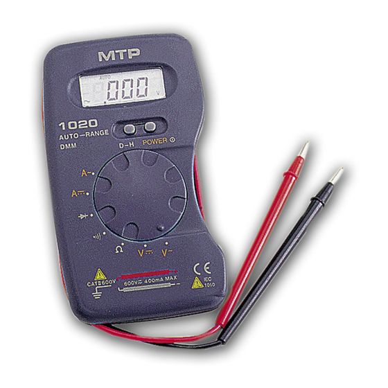
AUTO RANGING
POCKET-SIZED
DIGITAL MULTIMETER
OPERATOR'S
INSTRUCTION MANUAL
SAFETY INFORMATION
This meter has been designed according to IEC-1010 concerning
Electronic measuring instruments with an overvoltage category (CAT II) and
pollution2.
Follow all safety and operating instructions to ensure the meter is used
Safely and is kept in good condition.
With proper use and care, your digital multimeter will give you years of
satisfactory service.
DURING USE
• Never exceed the protection limit indicated in the specifications for
each range of measurement.
• Never use the meter to measure voltages that might exceed 600V above
earth ground in category installations.
• Always be careful when working with voltages above 60V dc or 30V ac
rms. keep fingers behind the probe barriers while measuring.
• Do not perform resistance measurements on live circuits.
• Inspect test leads and probes for cracks, breaks or crazes in the
insulation before using the meter.
SAFETY SYMBOLS
Important safety information, refer to the instruction manual.
Advertisement
Table of Contents

Related Manuals for MTP MTP-1020

Summary of Contents for MTP MTP-1020
- Page 1 AUTO RANGING POCKET-SIZED DIGITAL MULTIMETER OPERATOR’S INSTRUCTION MANUAL SAFETY INFORMATION This meter has been designed according to IEC-1010 concerning Electronic measuring instruments with an overvoltage category (CAT II) and pollution2. Follow all safety and operating instructions to ensure the meter is used Safely and is kept in good condition.
- Page 2 Earth ground. Indicates compliance with requirements for double insulation. Fuse must be replaced with ratings specified in the manual. MAINTENANCE • Before opening case, always disconnect test beads from all energized circuits. • For continuous protection against fire, replace fuse only with ratings; F 500mA/250V (Quick Acting).
- Page 3 Input Impedance: 10MΩ AC VOLTAGE Range Resolution Accuracy ±0.8% of rdg ±0.5% of full scale ±3dgts ±0.8% of rdg ±0.5% of full scale ±3dgts 10mV ±0.8% of rdg ±0.5% of full scale ±3dgts 400V 0.1mV ±0.8% of rdg ±0.5% of full scale ±3dgts 600V Overload protection: 600V dc or rms ac for all ranges Input Impedance:10MΩ...
- Page 4 DIODE TEST Range Description Show the approx. forward voltage drop of the diode. Overload Protection: 250V rms ac AUDIBLE CONTINUITY TEST Range Description Built-in buzzer sounds when resistance is less than 50Ω. Overload Protection: 250V rms ac GENERAL CHARACTERISTICS Maximum voltage between CAT II 600V Terminals and earth ground Fuse Protection...
- Page 5 Low battery indication appears on the display Size 120X70X18mm Weight Approx.110g including batteries OPERATING INSTRUCTION DC VOLTAGE MEASUREMENT 1. Set the function switch at V position. 2. Connect test leads across the source or load under measurement. The Polarity of red lead connection will be indicated at the same time as the Voltage value.
- Page 6 1. Set the function switch at A position. 2. Open the circuit in which the current is to be measured ,and connect Test leads in series with the circuit and read LCD display. RESISTANCE MEASUREMENT 1. Set the function switch at Ω position.(Note: The polarity of red lead is positive”+”) 2.
- Page 7 appear on the LCD display. AUDIBLE CONTINUITY TEST 1. Set the function switch at position. 2. Connect test leads to two points of the circuit to be tested. If the Resistance is less than 50Ω,buzzer will sound. DATA HOLD APPLICATION D-H button is used to hold a measuring result.
- Page 8 electrical shock hazard. For protection against fire, replace fuse only with the specified ratings; F500mA 250V. Accessories Battery SR44 or LR44 Carrying Case Operating manual CAUTION: “Using this appliance in an environment with a strong radiated radio-frequency electromagnetic field (approximately 3V/m), may influence its measuring accuracy.
Need help?
Do you have a question about the MTP-1020 and is the answer not in the manual?
Questions and answers
Setting for battery test
The MTP-1020 does not have a specific "battery test" setting. However, if the battery needs replacement, a battery symbol will appear on the LCD display. The batteries used are SR44 or LR44.
This answer is automatically generated