
Related Manuals for MTP 2326

Summary of Contents for MTP 2326
-
Page 1: Table Of Contents
Table of Contents INSTRUCTION MANUAL TITLE PAGE 1. GENERAL INSTRUCTIONS Digital Multimeter Model MTP 2326 1.1 Precaution safety measures 1.1.1 Preliminary 1.1.2 During use 1.1.3 Symbols 1.1.4 Instructions 1.2 Protection mechanisms 2. DESCRIPTION 2.1 Instrument Familiarization 2.2 LCD Display 2.3 Key pad 2.4 Terminals... -
Page 2: General Instructions
Table of Contents 1. GENERAL INSTRUCTIONS This instrument complies with IEC 61010-1, CAT. III 1000V and CAT.Ⅳ 600V overvoltage standards. See Specifications. TITLE PAGE To get the best service from this instrument, read carefully this user's manual and respect the detailed safety 3.2.5 Capacitance measurement precautions. -
Page 3: During Use
* To avoid damages to the instrument, do not exceed the MAINS derived circuits. In the latter case, transient stresses are variable; for that reason, requires that the transient maximum limits of the input values shown in the technical withstand capability of the equipment is made known to the specification tables. -
Page 4: Symbols
voltage pulses at the test points can damage the multimeter. parts. * Before opening up the instrument, always disconnect from Use of a TV filter will attenuate any such pulses. * Use the 9V NEDA battery, properly installed in the Meter's all sources of electric current and make sure you are not battery case, to power the Meter. -
Page 5: Description
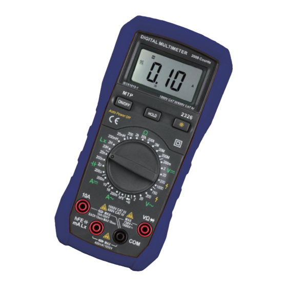
2. DESCRIPTION 2.2 LCD Display 2.1 Instrument Familiarization See Table 1 indicated for information about the LCD display. Figure 1.Display Table 1. Display Symbols Symbol Meaning The battery is low. Warning: To avoid false readings, which could lead to possible electric shock or personal injury, replace the battery as soon as the battery indicator appears. -
Page 6: Keypad
Table 1. Display Symbols (continued) 2.4 Terminals The Meter is in the Continuity Check mode. See Table 3 indicated for information about the terminals. Table 3. Terminals The Meter is in the Data Hold mode Terminal Description Volts. The unit of voltage. V, mV Millivolt. -
Page 7: Function Description
3.2 Measurement Functions 3. FUNCTION DESCRIPTION 3.2.1 AC and DC Voltage measurement 3.1 General Functions To avoid electrical shock and/or damage to the instrument, do not attempt to take any voltage 3.1.1 DATA HOLD mode measurement that might exceeds 1000Vdc or Data Hold mode makes the meter stop updating the 750Vac rms. -
Page 8: Resistance Measurement
3.2.2 Resistance measurement Use the diode test to check diodes, and other semi- To avoid electrical shock and/or damage to the conductor devices. The diode test sends a current through instrument, disconnect circuit power the semiconductor junction, and then measures the voltage discharge all high-voltage capacitors before drop across the junction;... -
Page 9: Capacitance Measurement
4. Connect the test leads to the resistance in the circuit The unit of Inductance is the farad (H). The Meter's being measured. Inductance ranges are 20.00mH, 200.0mH, 2.000H, and 5. When the test lead to the circuit is below approx. 30, 20.00H. -
Page 10: Technical Specifications
Current is the flow of electrons through a conductor. 4 TECHNICAL SPECIFICATIONS The Meter's DC current ranges are 200.0mA and 10.00A; 4.1 GENERAL SPECIFICATIONS AC current ranges are 200.0mA and 10.00A. Environment conditions: To measure current: 1000V CAT. III and 600V CAT.Ⅳ 1. -
Page 11: Dc Voltage
Overload protection: 250V dc or 250Vac rms. Accuracy is specified for one year after calibration, at Open Circuit Voltage: Less than 700mV. operating temperatures of 18 ℃ to 28 ℃ , with relative 4.2.4 Diode humidity at 0% to 75%. Range Resolution Function... -
Page 12: Dc Current
Overload protection: fuse (FF400mA/1000V). 5. MAINTENANCE Do not attempt to repair or service your Meter unless you are 4.2.9 DC Current qualified to do so and have the relevant calibration, Range Resolution Accuracy performance test, and service information. ±(1.5% of rdg+1 digit) 200mA 0.1mA 5.1 General Maintenance... - Page 13 terminals. Les Instruments Use a screwdriver to unscrew the two screws secured on the battery cover. Take out the battery cover from the meter. Instruments Remove the used batteries or damaged fuse. Replace with the new 9V batteries (6F22)or new fuse. ...
Need help?
Do you have a question about the 2326 and is the answer not in the manual?
Questions and answers