
Related Manuals for ThermoForma 3920


Summary of Contents for ThermoForma 3920
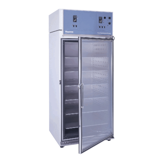
- Page 1 Model 3920 29 cu. ft. Capacity Environmental Chamber Operating and Maintenance Manual Manual No: 7033920 Rev. 12...
- Page 2 New door - updated electrical schematics 19207/IN-2827 6/28/00 Revised electrical schematics and parts list (250200 to 300345 contactor) 4/20/00 Quark format 18896/SI-7773 2/8/00 New 3920 schematic - wiring harness, 430305 11/22/99 Corrected Section 2.9 Offset Configuration 17861/IN-2439 8/10/99 Updated schematics for CSA ECR/ECN DATE...
- Page 3 Model 3920 _________________________________________________________________________________ Important operating and/or maintenance instructions. Read the accompanying text carefully. Ce symbole attire l'attention de l'utilisateur sur des instructions importantes de fonctionnement et/ou d'entretien. Il peut être utilisé seul ou avec d'autres symboles de sécurité. Lire attentivement le texte d'accompagnement.
- Page 4 Model 3920 _________________________________________________________________________________...
-
Page 5: Table Of Contents
Section 3 - Control Panel Operation ....3 - 1 3.1 The 3920 Control Panel ..... . .3 - 1 3.2 Setting the Operating Temperature (Figure 3-3) . -
Page 6: Section 1 - Receiving
2.3 RS-232 Output Interface and Remote Alarm stances, move the shipment from the receiving area. Connector The Model 3920 is equipped with an RS-232 Serial Communication Interface for the remote transmission of tem- 1.3 Responsibility for Shipping Damage perature data. The remote alarm connections are also included on the terminal strip. -
Page 7: Remote Alarm Contacts
Note: When the chamber temperature control setpoint is changed, the overtemp safety thermostat must be reset to For Model 3920, plug the provided 10 ft. power cord with accommodate the change. the NEMA 5-20 plug into the power outlet connection on the back of the cabinet, then into the grounded dedicated electrical circuit. -
Page 8: Preparing The (Optional) Cobex Recorder
Model 3920__________________________________________________________________Installation and Start-Up c. Changing the Pen 2.8 Preparing the (Optional) CoBex Recorder 1. Using a small flat blade screwdriver, loosen the 2 screws a. Installing the Battery holding the pen arm and remove the pen and arm as an assembly. -
Page 9: Offset Calibration
Model 3920__________________________________________________________________Installation and Start-Up 2.9 Offset Calibration To turn the hardware lockout back on: 1. Press the Up and Down Arrow keys simultaneously for It may be necessary to calibrate the temperature controller 3 seconds. The word “InPt” will appear in the upper dis- to match an independent temperature sensor. -
Page 10: 1900140 Ir Co Option
2.12 1900140 IR CO Option c. CO Controller Calibration This section applies to units with the 1900140 IR CO Enter the Setup Menu by pressing the t up-arrow and option only. 6down-arrow keys simultaneously on the Watlow 93 controller for three seconds. The lower display shows the Lock parameter, and the upper display shows a. - Page 11 Model 3920__________________________________________________________________Installation and Start-Up 3940 (WATLOW 982) CONFIGURATION RECORD CUSTOMER: JOB NUMBER: UNT SERIAL NUMBER: CONTROL TYPE: Temperature PREPARED BY: DATE COMPLETED BY: DATE Switch Configuration: Main Boards Input 1 Board Output 3 Option board Jumper switch setting: Form B Software Configuration: Operations Menus SYS: Ei1S...
- Page 12 Model 3920__________________________________________________________________Installation and Start-Up WATLOW 93 CONFIGURATION RECORD CUSTOMER: JOB NUMBER: UNT SERIAL NUMBER: CONTROL TYPE: PERPARED BY: DATE COMPLETED BY: DATE: Operational Parameters: 0.05 -5.0 Setup Parameters: 4-20 20.0 Notes: * calibration offset may vary from unit to unit Important: Input switches 1&2 must be set to "on"...
-
Page 13: Section 3 - Control Panel Operation
Model 3920 __________________________________________________________________Control Panel Operation Section 3 - Control Panel Operation The defrost switch must be turned on when the temperature setpoint is 10°C, or below. Overtemp Safety Control, Indicator Light, and Audible Alarm (Figure 3-2) The overtemp safety thermostat should be set slightly above the operating temperature of the incubator. -
Page 14: Setting The Operating Temperature (Figure 3-3)
Model 3920 __________________________________________________________________Control Panel Operation 3.2 Setting the Incubator’s Operating Temperature Looking at the top of (Figure 3-3) the module, locate the red DIP switch indicated in Figure 3-5. With a finger- The Watlow temperature nail or small screwdriver, controller’s upper numerical... -
Page 15: Air Exchange Ventilator Caps
Model 3920 ___________________________________________________________________Routine Maintenance Press the down arrow key until the Section 4 - Routine Maintenance 2 becomes 0 (zero) as shown in Figure 3-9. Press the Display key to return to 4.1 Cleaning the Incubator showing the setpoint and actual tem- peratures. - Page 16 • Use sterile, distilled or demineralized wqater. • Avoid spraying cleaner on the CO 2 sensor. • Do not use powdered gloves for tissue cultures. •Millcreek Road, Box 649 •Marietta, Ohio 45750 USA •740-373-4763 •USA and Canada 888-213-1790 •Telefax: 740-373-4189 •http://www.service@thermoforma.com 4 - 2...
- Page 17 Model 3920_______________________________________________________________________________________________________________Preventive Maintenance Preventive Maintenance for Model 3920 Refer to Manual Section Action Daily Weekly Yearly Inspect door latch, hinges and door gasket seal Check air exchange ventilator caps for adjustment; open or close as required Perform a complete decontamination procedure. Wipe down interior, shelves, Between Experiments side panels with disinfectant.
-
Page 18: Section 5 - Service
Model 3920 _______________________________________________________________________________Service 5.3 Replacing the Temperature Sensor Section 5 - Service 1. Locate the probe mounting plate in the center of the right side of the incubator interior. Servicing must be performed by qualified service 2. Open the mounting plate by removing the screws that personnel only! hold it in place. -
Page 19: Setting The Door Heater Control
Model 3920 _______________________________________________________________________________Service 8. Remove the nine 5/16” x 4” hex head bolts, lock wash- 5.5 Setting the Door Heater Control ers, and two flat washers which secure the top assembly to the cabinet. Note the washer arrangement on the bolts. -
Page 20: Section 6 - Specifications
Model 3920 _________________________________________________________________________Specifications Section 6 – Specifications Temperature Fittings Control ±0.3°C @ +25°C to +37°C Drain Port 3/8” OD Copper Range 0°C (32°F) to +60°C (140°F) Unit Heat Load Sensor 115V 5500 BTUH (1600W) Controller Digital electronic proportional 220V 6000 BTUH (1750W) -
Page 21: Section 7 - Parts List
Model 3920 ___________________________________________________________________________Parts List Section 7 - Parts List Part No. Description 290163 Sensor, RH/Temp Control 230066* Fuse, Ceramic 10A 350V 290162 RH/Temp Control Signal Conditioner 400051 Power Supply 231186 Controller, Watlow 982 Auto Tune 320277 Triac, 25A 403940 Thermostat, B-10 0-220°F (coated) 403941 Thermostat, B-20 10-220°F (coated) - Page 23 Model 3920 ____________________________________________________________________Electrical Schematics 8 - 2...
- Page 24 Model 3920 ____________________________________________________________________Electrical Schematics 8 - 3...
- Page 25 Model 3920 ____________________________________________________________________Electrical Schematics 8 - 4...
- Page 27 Thermo Forma Millcreek Road, P.O. Box 649 Marietta, Ohio 45750 U.S.A. Telephone (740) 373-4763 Telefax (740) 373-4189...
Need help?
Do you have a question about the 3920 and is the answer not in the manual?
Questions and answers