Advertisement
Quick Links
I N S T R U C T I O N S
IN THE BOX
Make sure you have everything
shown here.
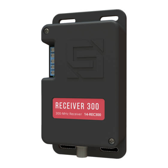
WHAT'S WHAT
1. DIP switches
2. RF status LED
3. Power and relay terminals
4. Coaxial antenna connector
SETUP
1. Remove screws from Receiver 300 unit cover and
remove cover to reveal DIP switches.
CAUTION! Be gentle with coaxial connection
when removing cover. Do not let cover hang
free; doing so may damage unit!
2. Set DIP switches to desired positions.
NOTE: For best results, we recommend using
the Security Brands Remote 300 (14-R300).
NOTE: By default, the DIP switches are matched
to the default DIP switch positions on the
Remote 300 and other 300-MHz remotes.
For security reasons, we recommend using
custom DIP switch positions.
NOTE: Some DIP switches may be labeled
differently. The position labeled 10 corresponds
to the position labeled 0, and some DIP switches
have the off position labeled as OPEN.
RECEIVER 300
Receiver 300
Antenna
1
2
(cover removed)
1 of 2
1.5-foot Coaxial Cable
Receiver 300
ON
1
2
3
4
5
6
DIP Switches on Receiver 300
(default positions)
Model 14-REC300
Coaxial Connector
3
4
Receiver 300
(cover in place)
7
8
9
10
Advertisement

Related Manuals for Security Brands 14-REC300

Summary of Contents for Security Brands 14-REC300
- Page 1 2. Set DIP switches to desired positions. NOTE: For best results, we recommend using the Security Brands Remote 300 (14-R300). NOTE: By default, the DIP switches are matched to the default DIP switch positions on the Remote 300 and other 300-MHz remotes.
- Page 2 DIP switch positions on both HELP or email the receiver and the remote(s) match. techsupport@securitybrandsinc.com Two-Year Limited Warranty Visit securitybrandsinc.com/warranty/ for details © 2021 Security Brands, Inc. All rights reserved. 2 of 2 I-14REC300-EN Rev. B (12/2021)
Need help?
Do you have a question about the 14-REC300 and is the answer not in the manual?
Questions and answers