Table of Contents
Advertisement
Quick Links
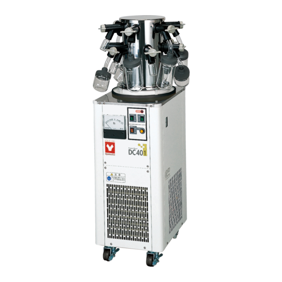
Freeze Dryer
Model
DC401
Instruction Manual
- First Edition -
Thank you for choosing DC series freeze
dryers from Yamato Scientific Co., Ltd.
For proper equipment operation, please read
this instruction manual thoroughly before
use. Always keep equipment documentation
safe and close at hand for convenient future
reference.
WARNING!:
Read instruction manual warnings and
cautions carefully and completely before
proceeding.
Yamato Scientific America Inc.
Santa Clara,CA
Printed on recycled paper
Advertisement
Table of Contents

Related Manuals for Yamato DC401


Summary of Contents for Yamato DC401
- Page 1 DC401 Instruction Manual - First Edition - Thank you for choosing DC series freeze dryers from Yamato Scientific Co., Ltd. For proper equipment operation, please read this instruction manual thoroughly before use. Always keep equipment documentation safe and close at hand for convenient future reference.
-
Page 3: Table Of Contents
10. SPECIFICATIONS ................23 Main Unit ........................23 Optional Accessories ....................24 11. WIRING DIAGRAM ................25 DC401 ........................25 12. REPLACEMENT PARTS ..............26 13. LIST OF HAZARDOUS SUBSTANCES .......... 27 ... -
Page 4: Safety Precautions
1. SAFETY PRECAUTIONS Explanation of Safety Symbols A Word Regarding Symbols Various symbols are provided throughout this text and on equipment to ensure safe operation. Failure to comprehend the operational hazards and risks associated with these symbols may lead to adverse results as explained below. -
Page 5: Symbol Glossary
1. SAFETY PRECAUTIONS Symbol Glossary Warning General Danger!: High Danger!: Danger!: Moving Danger!: Blast Warning Voltage Extremely Hot Parts Hazard Caution Caution: Do Not Caution: Caution: Burn Caution: May General Caution Heat Without Shock Hazard! Hazard! Leak Water! Water! Caution: Water Caution: Toxic Only Chemicals... -
Page 6: Warnings & Cautions
1. SAFETY PRECAUTIONS Warnings & Cautions WARNING! Never operate equipment near combustible gases/fumes. Do not install or operate DC series unit near flammable or explosive gases/fumes. Unit is NOT fire or blast resistant. Negligent use could cause a fire/explosion. See “List of Hazardous Substances” (P.28). Always ground equipment. -
Page 7: Warnings & Cautions
1. SAFETY PRECAUTIONS Warnings & Cautions CAUTION! DO NOT operate equipment during thunderstorms. In the event of a thunderstorm, terminate operation and turn off main power switch (ELB) immediately. A direct lightning strike may cause damage to equipment, or result in fire or electric shock. DO NOT touch ice in cold trap. -
Page 8: Pre-Operation Procedures
2. PRE-OPERATION PROCEDURES Installation Precautions & Preparations WARNING! 1. Equipment MUST always be grounded properly. Always connect power cable to a grounded outlet to prevent electric shock from power surges. Never connect ground wire to gas lines, water pipes, telephone grounding lines or lightening rods. - Page 9 Install unit on a level and even surface. Failure to do so may result in abnormal vibrations or noise and damage to the refrigeration system. Approximate unit weight: DC401: 47kg. Handle with care. Transport and installation should always be performed by two or more people.
- Page 10 Failure to do so may result in fire or electric shock. Contact a local dealer or Yamato sales office for information about replacing power cable if it is damaged.
-
Page 11: Installation Procedures
2. PRE-OPERATION PROCEDURES Installation Procedures 1. Unlock caster. Pull up on lever to release caster lock (only two front casters are equipped with locks). 2. Move unit in place for installation. Wheeling unit over large bumps or crevices may cause excessive shock to unit or Release damage to casters. -
Page 12: Component Names & Functions
3. COMPONENT NAMES & FUNCTIONS Unit Overview Cold Trap Front view Vacuum Gauge Power Switch (Earth Leakage Breaker) Control Panel Cooling Vent Caster Rear view Vacuum Pump Power Outlet Vacuum Port Power Cable Drain Outlet... -
Page 13: Control Panel
3. COMPONENT NAMES & FUNCTIONS Control Panel ⑥ ⑤ TROUBLE ① ④ DEFROST REFRIGE ② ③ PUMP → START Part Name Function ① Refrigeration Switch Activates/deactivates refrigeration system. ② Vacuum Pump Switch Enables/disables pump operation. ③ Pump Start Switch Starts pump operation. ④... -
Page 14: Operation Procedures
4. OPERATION PROCEDURES Pre-freezing For the pre-freezing process, freeze samples quickly and completely through, at a temperature sufficiently lower than sample eutectic (solidification) point . Freeze as thinly as possible so that sample will not have a chance to melt before the drying process can dry it. Likewise, external heat may influence and begin melting samples with a low eutectic table, if it is frozen too thickly in the container. -
Page 15: Main Operation
Main Operation Prepare dryer manifold, vacuum pump, vacuum hose, tandem tube, and other equipment necessary to operation process. Example vacuum pump: PD52 (from YAMATO Scientific) Displacement volume: 50/min, maximum vacuum pressure: 6.7×10 inlet pipe diameter: 18mm (or equivalent) Turn "ON" main power switch (ELB). - Page 16 Time required to minimum temperature: PUMP (external temperature: 20°C, no load) → START DC401: 50min. This time is a guideline and may vary. (There will be condensation near the bottom of vacuum chamber when sufficient time has passed)
- Page 17 4. OPERATION PROCEDURES Main Operation Confirm by looking at the vacuum gauge, that vacuum 8. Check vacuum gauge chamber has sufficiently decompressed. (10Pa-20Pa) Install the pre-frozen sample container on the vacuum 9. Install sample container and open valve, turn the valve knob so that “VAC” is in the top valve "VAC"...
- Page 18 4. OPERATION PROCEDURES Main Operation When process has finished, turn valve from “VAC” to 12. Close vacuum valve "VENT" “VENT” (“VENT” in the top position) to normalize pressure in the sample container and remove the container. Hold container securely when removing, so that it is not dropped.
-
Page 19: Defrost
Handle by pulling up on handle and turn OFF the defrost switch. Defrost auto stop. DC401: Approx. 20min. Turn OFF defrost switch manually. Remove the drain hose cap, and drain remaining 3. Drain water water from the trap into a drain basin or other receptacle. -
Page 20: Handling Precautions
If unit begins emitting smoke or abnormal odors for reasons unknown, turn off main power (ELB) immediately, disconnect power cable from power supply, and contact a local dealer or Yamato sales office for assistance. Continuing to operate without addressing abnormalities may cause fire or electric shock, resulting in serious injury or death. - Page 21 5. HANDLING PRECAUTIONS Upper limit of inside bath temperature. Do not run successive operations when cold trap temperature is above -20°C. Vacuum grease application. Vacuum pressure is weakened and vacuum leaks may occur if any contaminants are allowed to build up on vacuum connection components. If contaminant buildup is found in any vacuum connection joints, clean and reapply vacuum grease as needed.
-
Page 22: Maintenance Procedures
After cleaning the cooling fins in the same way, reinstall vent cover. Be careful not to bend or crush the fins while cleaning. Do not contact cooling fins with bare hands or fingers. Contact a local dealer, or Yamato sales office for further assistance. -
Page 23: Storage & Disposal
Dispose of or recycle this unit in a responsible and environmentally friendly manner. Yamato Scientific Co., Ltd. strongly recommends disassembling unit, as far as is possible, in order to separate parts and recycle them in contribution to preserving the global environment. -
Page 24: Troubleshooting
8. TROUBLESHOOTING Troubleshooting Guide Symptom Possible Causes/Solutions Power cable is not connected properly or securely. Power failure in progress. Unit will not power on. Main power switch (ELB) is “OFF” Cooling fins are clogged with dust or debris. ... -
Page 25: Service & Repair
Guaranteed Supply Period for Repair Parts Guaranteed maximum supply period for repair parts is 7 (seven) years from date of discontinuation for DC401 freeze dryer models. “Repair parts” is defined as components which, when installed, allow for continued unit operation. -
Page 26: Specifications
External dimensions W340×D450×H920 mm Weight Approx. 53Kg Power requirements 220V AC, 50/60Hz, 2.6A Vacuum silicon grease (TORAY H.V.G), Vacuum hose (φ12×φ30 Included items ×1.5m), DC401 instruction manual, Pirani gauge instruction manual ※Performance based on operation room temperature (20°C), no load... -
Page 27: Optional Accessories
10. SPECIFICATIONS Optional Accessories Name Specification Product code Mounting valve Inner dia.: 18.5mm Mounting valve pitch 96mm Flask Mounting Vacuum 212560 Chamber Number of ports φ195×H303 mm Dimensions Mounting valve Inner dia.: 18.5mm Mounting valve pitch 80mm Manifold A 212561 Number of ports Dimensions W304×D60×H263 mm... -
Page 28: Wiring Diagram
11. WIRING DIAGRAM DC401... -
Page 29: Replacement Parts
12. REPLACEMENT PARTS DC401 Symbol Part Name Specification Manufacturer Code No. Solenoid valve (refrigeration) NEV-603DXF Saginomiya 3020060004 Solenoid valve (defrost) SEV-502DXF Saginomiya 3020060003 Solenoid valve (VAC) AG33022 AC100V 3200010018 BJS2032N 20A Earth leakage breaker Panasonic 2060050002 X3, 4, 6 Relay... -
Page 30: List Of Hazardous Substances
13. LIST OF HAZARDOUS SUBSTANCES Never process any explosive, flammable samples and also samples contained with those substances. ①Nitroglycol, Glycerine trinitrate, Cellulose Nitrate and other explosive nitrate esters ②Trinitrobenzen, Trinitrotoluene, Picric Acid and other explosive nitro compounds ③Acetyl Hydroperoxide, Methyl Ethyl Ketone Peroxide, Benzoyl Peroxide and other organic peroxides ④Metallic Azide, including Sodium Azide, etc. - Page 31 Yamato Scientific Co., Ltd. assumes no responsibility for malfunction, damage, injury or death, resulting from negligent equipment use. Never attempt to disassemble, repair or perform any procedure on DC401 units which are not expressly mandated by this manual. Doing so may result in equipment malfunction, serious personal injury or death.
Need help?
Do you have a question about the DC401 and is the answer not in the manual?
Questions and answers