Table of Contents
Advertisement
Quick Links
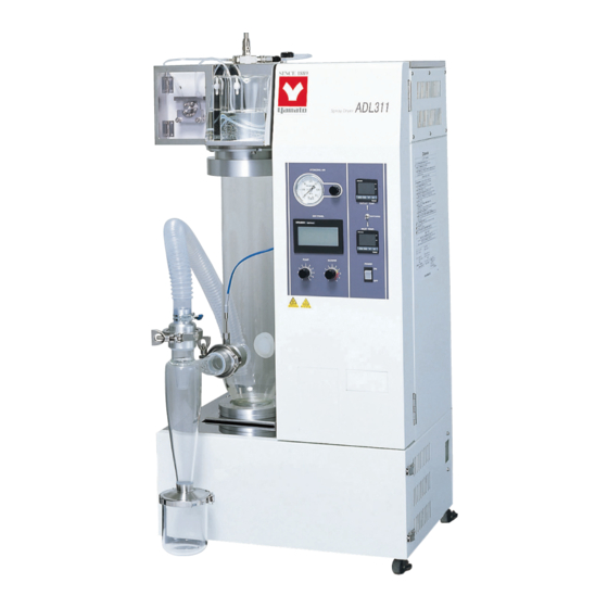
SPRAY DRYER
ADL311/ADL311S
Instruction Manual
● Thank you for purchasing "Spray Dryer, ADL 311/311SS" of
Yamato Scientific Co., Ltd.
● To use this unit properly, read this "Instruction Manual"
thoroughly before using this unit.
Keep this instruction manual around this unit for referring at
anytime.
: : : : WARNING!:
Carefully read and thoroughly understand the important
warning items described in this manual before using this
unit.
Yamato Scientific Co. LTD.,
- Version 3 -
This paper has been printed on recycled paper.
This paper has been printed on recycled paper.
This paper has been printed on recycled paper.
This paper has been printed on recycled paper.
Advertisement
Table of Contents

Related Manuals for Yamato ADL311


Summary of Contents for Yamato ADL311
- Page 1 Instruction Manual - Version 3 - ● Thank you for purchasing "Spray Dryer, ADL 311/311SS" of Yamato Scientific Co., Ltd. ● To use this unit properly, read this "Instruction Manual" thoroughly before using this unit. Keep this instruction manual around this unit for referring at anytime.
-
Page 2: Table Of Contents
9. After Service and Warranty............31 When requesting a repair ............. 31 10. Specification ............... 32 11. Wiring Diagram ..............34 ADL311 Wiring Diagram .............. 34 ADL311 SWiring Diagram ............. 36 12. System Chart ..............38 System Chart ............... 38 13. -
Page 3: Safety Precautions
1. Safety precautions Explanation of pictograms About pictograms A variety of pictograms are indicated in this operating instruction and on products for safe operation. Possible results from improper operation ignoring them are as follows. Be sure to fully understand the descriptions below before proceeding to the text. -
Page 4: List Of Symbols
1. Safety precautions List of symbols Warning Danger!: High Danger!: High Danger!: Moving Danger!: Hazard General warnings voltage temperature part of explosion Caution Caution for no Caution for water General cautions Electrical shock! Burning! liquid heating! leak! Poisonous For water only material Prohibitions Do not... -
Page 5: Warning・Cautions
1. Safety precautions Warning・ ・ ・ ・ Cautions Warning Do not use this unit in an area where there is flammable or explosive gas Never use this unit in an area where there is flammable or explosive gas. This unit is not explosion-proof. - Page 6 1. Safety precautions Warning・ ・ ・ ・ Cautions Caution During a thunder storm During a thunderstorm, turn off the power key immediately, then turn off the circuit breaker and the main power. If this procedure is not followed, fire or electrical shock may be caused. If the electric failure shall be occurred, •...
-
Page 7: Before Using This Unit
Color Wiring equipment side is turned "OFF" when connecting power cord Black Voltage Side without fail. Note that the ADL311 does not attach the power plug as standard component. Select the appropriate power White Voltage Side plug and terminal matching to the power capacity of the power... - Page 8 Before using this unit Precautions when installing the unit Warning 4. Do not use this unit in an area where there is flammable or explosive gas • Never use this unit in an area where there is flammable or explosive gas. This unit is not explosion-proof.
- Page 9 2. Before using this unit Precautions when installing the unit Warning 6. Do not modify 7. Do not topple or tilt this unit Set this unit to the flattest place. Setting Modification of this unit is strictly this unit on rough or slope place could cause prohibited.
-
Page 10: Service Receptacle Capacity
2. Before using this unit Service receptacle capacity Service receptacle capacity Apply the 100V 2A or less service receptacle for this unit. Connecting the service receptacle with its capacity over 2A blowouts the fuse, and the power source to the service receptacle is shut down. For resetting this damage, replace the fuse in the fuse holder on the right side of the back of the unit. -
Page 11: Names Of Parts And Their Function
3.Names of parts and their function Main unit + GF300 set Front side Air spray tube Spray nozzle Nozzle detection sensor BOX Specimen table *For ADL311S only Specimen sending Operation panel pump Suction hose Drying chamber For blind plate for recorder (optional) Outlet temperature sensor... -
Page 12: Operation Panel
3.Names of parts and their functions Operation panel ⑧ ⑦ ⑤ ④ ⑥ ③ ⑨ ① ② Name Operation/action Power switch This is used to turn power ON/OFF. ① Blower control dial This is used to set an air amount. ②... -
Page 13: Operating Procedures
4. Operating procedures Preparations Selecting the power supply First switch the power supply terminal First check that the switches of the control assembly and the ELB are OFF and then connect the power cord securely to the power supply meeting the specified voltage and current. Ordinary, the unit has been specified to AC200V. - Page 14 4. Operating procedures Preparations Connect the nipple (φ7) at the rear of the upper frame and the compressor or other pressurized air units with the included pressure-proof hose and then securely tighten it using a hose band. Adjust the discharge pressure of the compressor to be constant (0.3MPa or less) using the pressure reducing valve.
- Page 15 4. Operating procedures Preparations Insert the pipe in the center of the distributor and twist it all the way. Temp. sensor connecting socket Pipe Align the groove with the stage positioning pin and then install the drying chamber. Open the left side door and turn the handle while holding the drying chamber by hand to lift the stage.
- Page 16 4. Operating procedures Preparations (11) Connect the cyclone following the step numbers below. 2. Connection of the teflon hose and the connecting 1. Connecting the cyclone and ferrule D the glass chamber Power clamp 40A Packing 40A Connecting ferrule D 3.
-
Page 17: Operating Method
4. Operating procedures Operating method Please refer to the sample operating method below that uses settings for a standard sample. Sodium chloride water solution NET 100g Solid content density:5wt% (1) Turn the ELB on the right side of the main unit ON. (2) Turn the power switch on the operation panel of the main unit ON. - Page 18 Turn the blower switch ON and set air amount. Example: Air amount 0.45m /min SPRAY DRYER (See "Dry air amount correspondence table" on P.20.) ADL311(S) *Use HELP key to move to the manual/language select BLOWER HELP screen, confirm the operation manual of the unit, and then you can select the OSD language (English, Japanese, Chinese).
- Page 19 4. Operating procedures Operating method When the inlet and the outlet temperatures have reached the temperatures you want, set the spray pressure, turn Open the pump FWD switch ON and send distilled water. Example: Set the spray pressure to 0.1MPa when the outlet temperature has risen to around 80℃.
- Page 20 4. Operating procedures Operating method (10) When the outlet temperature has become stable, change the specimen with the actual one. At this time the outlet temperature will change slightly and adjust liquid sending speed again when necessary. Example: Change specimen to 100g of 5% sodium chloride solution Finishing process (11) When specimen has been sent, change the specimen...
- Page 21 4. Operating procedures Operating method KEY PANEL Description of indication lamps You can confirm the operating statuses of switches one the KEY PANEL by checking whether a specific lamp is on or off. Each lamp will be turned on at the upper right corner on the KEY PANEL. You can control temperature by setting a temperature on the outlet side temperature controller while the lamp is on.
-
Page 22: Related Figure Between Blower And Temperature/Drying Air Quantity (Reference)
4. Operating procedures Related Figure between Blower and Temperature/Drying Air Quantity (Reference) The temperature around outlet is depended on the flow rate of the blower. Also, this temperature is depended on the clogging of the filter in the blower. Refer to the following table for each dial value of the blower and the display temperature around inlet/outlet as the guideline of the work. -
Page 23: Handling Precautions
5. Handling Precautions Warning 1. Substances that cannot be used Never use an explosive, a flammable, or a substance that contains them. Otherwise, an explosion or a fire may result.ADL311S supports organic solvents by connecting it to the optional GAS410. Carefully read the operation manual of GAS410 and take special care for handling of organic solvents. -
Page 24: Drying Method Under Appropriate Condition
5. Handling Precautions Drying Method under Appropriate Condition (1) The best appropriate drying condition is differed depending on the sample to be dried. Inquire the data for the partial example of various samples. (2) Adjust the drying condition so as to match to the various errors to be possible to occur such as too much adhesion of the sample to the drying chamber, too high density of the sample, too low temperature around inlet, too high or too low pressure of spray air, too much feeding amount of sample. -
Page 25: Caution During Operation
5. Handling Precautions Caution during operation (1) Never fail to connect the earth wire when connecting the power supply. (2) コンプレッサからの加圧空気は 0.3MPa 以下で圧力一定にしてください。 (3) Do not heat up the temperature around outlet over 100 Celsius degree, for the material of the suction/exhaust hose, material of the filter, and performance of the blower may be deteriorated. -
Page 26: Maintenance Method
6. Maintenance Method Daily Inspection and Maintenance Warning ● Disconnect the power cable from the power source when doing an inspection or maintenance unless needed. ● Perform the daily inspection and maintenance after returning the temperature of this unit to the normal one. - Page 27 6. Maintenance Method Daily Inspection and Maintenance Filter Cleaning ● Clean up the filter in blower periodically. 1) Open the door at the bottom of the front surface of the unit, and disconnect the hose from the blower. 2) Open the front cover by removing the two fastening plates for the cover from the upper surface of the blower, and open the front cover, and take the filter out.
-
Page 28: Long Storage And Disposal
7. Long storage and disposal When not using this unit for long term / When disposing Caution Warning When not using this unit for long term… When disposing… ● Turn off the earth leakage breaker and original ● Keep out of reach of children. power source for safe without fail. -
Page 29: When A Trouble Occurs
8. When a trouble occurs Safety unit and error indications The table shows possible causes of activation of the safety unit and solutions. [Error indication] When an abnormality occurs to the inlet temperature controller or the outlet temperature controller, the touch panel at the operation panel displays the error screen. When an abnormality occurred, confirm description of the error and implement appropriate solutions. -
Page 30: Confirmation And Language Select For The Manual
8. When a trouble occurs Confirmation and language select for the manual You can select English or Chinese with the language select function as the OSD language for the manual. [Confirmation and language select for the manual] Pressing ESC key will return to the standby screen. -
Page 31: Trouble Shooting
8. In the Event of Failure… Trouble Shooting Symptoms Possible causes Countermeasures The POWER does ELB is turned OFF Turn the ELB ON not turn ON. Malfunction of the power supply Check the power supply circuit The wire ire short-circuited. Replace the cord Malfunction of power switch Replace the power switch... - Page 32 ◆ In the case if the error other than listed above occurred, turn off the power switch and primary power source immediately. Contact the shop of your purchase or nearest Yamato Scientific Service Office.
-
Page 33: After Service And Warranty
9. After Service and Warranty When requesting a repair When requesting a repair If any trouble occurs, immediately stop operation, turn the power switch off, pull out the power plug and contact your dealer, our sales office or our customer service center. Information necessary for requesting a repair ●... -
Page 34: Specification
Attached accessories ・ Tetlon braded hose 5m (for connecting pressurized air) ・ Hose clamp ・ Fuse ・ O-ring ・ Earth wire ・ Warranty card ・ Operation manual ADL311S, compared to ADL311, supports connection to the organic solvent recovery unit GAS410. - Page 35 10. Specification Model GF300 Amount water Max. Approx. 1300ml/h evaporation Spray nozzle Binary Nozzle 1A Drying chamber Made from super hard glass Cyclone Made from super hard glass Container for product Made from super hard glass Dust removal Pulse jet type (used the pressuring air blower mechanism for GB210 nozzle tip model) Weight...
-
Page 36: Wiring Diagram
11. Wiring Diagram ADL311 Wiring Diagram... - Page 37 11. Wiring Diagram ADL311 Wiring Diagram Symbol Part name Symbol Part name Electric Leakage Breaker Blower volume Stepdown transformer Liquid sending pump volume T1~T3 Terminal block PULSE JET solenoid valve T-Panel Touch panel Blower motor Sequencer Liquid sending pump motor TH1・TH2...
-
Page 38: Adl311 Swiring Diagram
11. Wiring Diagram ADL311S Wiring Diagram... - Page 39 11. Wiring Diagram ADL311S Wiring Diagram Symbol Part name Symbol Part name Electric Leakage Breaker PULSE JET solenoid valve Stepdown transformer Solenoid valve for switching GAS pipes T1 to T3 Terminal block Blower motor T-Panel Touch panel Liquid sending pump motor Sequencer Service outlet TH1 &...
-
Page 40: System Chart
12. System Chart System Chart For connecting optional unit (GAS410) Only ADL311S Connecting pressurized air Suction Number Part name Number Part name Heater Blower ① ⑨ Inlet temperature sensor Solenoid valve ② ⑩ 3-way solenoid valve Distributor ③ ⑪ (ADL311S only) Drying chamber Needle valve ④... -
Page 41: Principle Of Operation
13. Principle of Operation Principle of Operation Refer to " System Chart" on P.38. The sample is fed from the appropriate container to ⑭ spray nozzle with ⑮ feeding pump. Moreover, the compressed air pressure from the compressor is regulated by ⑫ needle valve, and sent to ⑭... -
Page 42: Replacement Parts Table
14. Replacement parts table Common parts for ADL311/ADL311S Part name Standards Manufacturer Code No. AD311S-40440 Yamato Scientific ※ Packing (C) LT00027737 Neoprene rubber AD311S-40430 Yamato Scientific ※ Packing (D) LT00027734 Neoprene rubber AD311S-40550 Yamato Scientific ※ Packing (E) LT00027740 Neoprene rubber... - Page 43 Stepdown transformer AD21-015KB2 TOYOZUMI LT00000982 Switching power LEA50F-24 COSEL LT00027661 Fan control substrate YY0609-A/FSPC Ryowa LT00020329 Liquid tube GAS41-40610 Silicone Yamato Scientific LT00027796 Fuse FGMB-125V2A-200P MISUMI LT00027794 Parts for ADL311S Part name Standards Manufacturer Code No. SS-01GL2 Nozzle Micro switch...
- Page 44 Yamato Scientific LT00028136 glass GF300-30060 Ultra hard Cyclone set Yamato Scientific LT00028785 glass Container holding band GF300-40000 Stainless steel Yamato Scientific LT00027540 Nozzle set GF300-30100 Yamato Scientific LT00028786 4210026021 ※ O-ring P16 4 types D Viton Yamato Scientific ※ Aluminum honeycomb...
-
Page 45: List Of Dangerous Substances
15. List of Dangerous Substances Never use explosive substances, flammable substances and substances that include explosive or flammable ingredients in this unit. Otherwise explosion or fire may result ADL311S supports organic solvents by connecting it to the optional GAS410. Carefully read the operation manual of GAS410 and take special care for handling of organic solvents. -
Page 46: Standard Installation Manual
16. Standard installation manual *Follow the items below to make installation. (Check the procedures separately for optional parts or products of special specifications.) Installation manager Installation Model Serial number Date Judgment (company name) manager Table of contents No. Section for №... - Page 47 16. Standard installation manual Table of contents No. Section for № Item Implementation method Judgment reference in manual Perform commissioning 4. Operating procedures Operating ・ELB and the power switch ON method ・Set the setting select to INLET and ・ (1)・(2) set the INLET temperature to 150℃...
- Page 48 Be sure to use the unit strictly following the handling and operating instructions in this operating instruction. Yamato Scientific Co., Ltd. assumes no responsibility for an accident or a malfunction caused by use of this product in any way not specified in this operating instruction.
Need help?
Do you have a question about the ADL311 and is the answer not in the manual?
Questions and answers