Advertisement
Sargent Electrical Services Ltd.
1 INTRODUCING THE EC200 ELECTRONIC CONTROL SYSTEM
With the use of new technology and an innovative approach to user interfacing, the EC200 Power
Control System provides a complete control solution for a wide range of leisure vehicles.
The microprocessor controlled digital system allows the user to control equipment and view / edit
system information from a user-friendly control panel that incorporates a liquid crystal ' ALPHA-
NUMERIC' display.
The built in ' intelligence' prevents over discharge of the vehicle battery, allows greater control of the
water system and has a built in alarm clock / event timer to control equipment in the absence of the
user. With the addition of an optional plug-in remote control pack the Power and Auxiliary functions
can be operated by a key fob controller.
The system meets relevant UK legislation, including the requirements of BS7671, EN1648-1 and -2.
Further technical data is contained in section 5.
2 SYSTEM OVERVIEW
The following diagram shows the components that make-up the EC200 system. The system basically
comprises a Power Supply and control Unit (PSU2007) that houses the Mains 240v protection
equipment, a 200 watt 12v charger / power supply, and power control / protection for the 12v
equipment. The PSU2007 is connected to a Digital Control Panel via a data cable.
EC200 ELECTRONIC CONTROL SYSTEM
12v LEISURE
BATTERY
12v VEHICLE
BATTERY
12v
EQUIPMENT
SENSOR
INPUTS
REMOTE
PACK
Issue 03
EC200
PSU 2007
EC200
CONTROL PANEL
Page 1 of 11
Copyright 2005
240v
EQUIPMENT
240v
IN
TEMP
12 May 2005
Advertisement
Table of Contents

Related Manuals for Sargent EC200


Summary of Contents for Sargent EC200
- Page 1 Copyright 2005 1 INTRODUCING THE EC200 ELECTRONIC CONTROL SYSTEM With the use of new technology and an innovative approach to user interfacing, the EC200 Power Control System provides a complete control solution for a wide range of leisure vehicles. The microprocessor controlled digital system allows the user to control equipment and view / edit system information from a user-friendly control panel that incorporates a liquid crystal ‘...
-
Page 2: Mains Connection
Sargent Electrical Services Ltd. Copyright 2005 3 POWER SUPPLY UNIT – SYSTEM OPERATION 3.1 INTRODUCTION For the safe operation of all electrical equipment within your Leisure Vehicle it is important that you read and fully understand these instructions. If you are unsure of any point please contact your dealer / distributor for advice before use. -
Page 3: Fault Table
Sargent Electrical Services Ltd. Copyright 2005 G) Turn the PSU2007 ON. Locate the red power switch on the PSU2007 and turn to the ON (I) position. The switch will illuminate when turned on. H) Check operation of equipment. It is now safe to check the operation of the 12v and 240v equipment. - Page 4 Sargent Electrical Services Ltd. Copyright 2005 Power switch on control panel not Turn power on at control panel switched to ON Recharge battery, check fuses, check Battery flat / Battery fuse blown charging voltage is present at battery Check all fuses are intact and the correct...
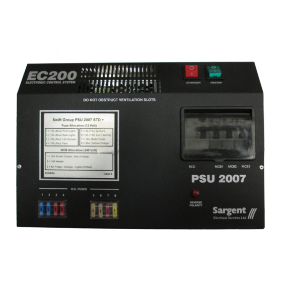
- Page 5 Sargent Electrical Services Ltd. Copyright 2005 3.5 FUSE / MCB TABLE WARNING When replacing fuses always replace a fuse with the correct value. NEVER replace with a higher value / rating as this could damage the wiring harness. If a replacement fuse ‘ blows’ do not keep replacing the fuse as you could damage the wiring harness.
-
Page 6: Control Panel Operation
Sargent Electrical Services Ltd. Copyright 2005 4 CONTROL PANEL OPERATION 4.1 Layout and Buttons The following diagram shows the control panel layout. POWER BATTERY SCROLL ON / OFF SELECT UP / ADJUST INDICATOR LAMPS (x4) SELECT SCROLL DOWN / PUMP(S) - Page 7 Options / Notes Main Control Panel display showing model The addition of a asterisk (*) in EC200 number (EC200), software version number the top left of the display v1.1H (v1.1), specification (H), current time (12:00) indicates that the alarm is set and Internal temperature (23.9°C) in...
- Page 8 Sargent Electrical Services Ltd. Copyright 2005 Use the select button (? ) to change <EXTERNAL> = The External pump will be operated by the pump switch <BOTH> = Both the Internal and External pumps will be operated simultaneously by the...
-
Page 9: Warning Messages
Sargent Electrical Services Ltd. Copyright 2005 4.4 Warning Messages This WARNING display indicates that the You can switch over to the Vehicle Vehicle battery voltage is low (10.9 volts or Leisure battery immediately Battery less). The panel will beep for one minute and... - Page 10 5.4 Declaration of Conformity Equipment: Leisure Power Control System Model name: PSU2007 / EC200 -STD / -DLX / -STD SW I hereby declare that the equipment named above has been designed to comply with the relevant sections of the above referenced approvals. The unit complies with all essential requirements of the Directives.
-
Page 11: Electrical Connection
Sargent Electrical Services Ltd. Copyright 2005 5.5 Electrical Connection 230 Volt INPUT OUTPUT OUTPUT View looking into PSU MCB 3 MCB 2 MCB 1 Note: both 9 connectors are identical 12 Volt OUTPUT INPUT SIGNAL INPUTS SIGNAL INPUTS View looking into PSU...
Need help?
Do you have a question about the EC200 and is the answer not in the manual?
Questions and answers
add a solar panel to ec200