Table of Contents
Advertisement
Quick Links
Advertisement
Table of Contents

Related Manuals for EYELA SD-1010


Summary of Contents for EYELA SD-1010
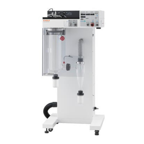
- Page 1 Spray Dryer Instruction Spray Dryer Manual SD-1010 This manual is designed to use this unit safely with the best performance. Read carefully the chapter [For safety operation] before operating this unit. Important Keep this instruction manual beside the unit. Tokyo Rikakikai Co., Ltd.
- Page 2 Precautions for your safety 1. Warning signal words However, if you know about them in advance, you This unit is not explosion-proof structured. can prevent most of these accidents. When a flammable sample or organic solvent is For that reason, this instruction manual defines used, handle it with care so that the liquid may not be spilled over.
- Page 3 2.Warning label A warning label is attached to the unit to refer to the most important clause. The attached position is shown below. Be careful to use the unit referring warning messages. * When the warning label is worn and hardly show the message, change it with a new one. Please order us a new label.
-
Page 4: Table Of Contents
Introduct This instruction manual describes the procedure of Read this manual carefully before operation. installation, operation, troubleshooting, maintenance/check-up, and disposal for Spray dryer model SD-1010. Table of contents 1.For safety operation 5-2.Operation 5-2-1.Preparing sample and distilled water 2.Outline 5-2-2.Operation 2-1. - Page 5 P a c k i n g This unit is packed in 2 cartons which are main unit and accessory parts. Check quantities referring to the below table. Part name Qty. 2.Rectification board 3.Exhaust hose,cuffs Main unit Rectification board Exhaust hose, cuff (2 pieces) 2.5m Stainless steel diamond clamp (for exhaust hose) Air piping connector(1/4')
-
Page 6: For Safety Operation
For safety operation Please pay attention to safety as this product becomes hot Warning Do not use flammable materials such an organic solvent. Do not use this unit to fry flammable materials such as organic solvent. This unit has a built-in heater, so it may ignite. Caution While operating unit, do not touch evaporator or cyclone. -
Page 7: Specifications
2-2 Specifications Product name Spray Dryer Model SD-1010 Evaporating rate Max 1500ml/h Drying air flow rate control range and 40~200°C (Outlet temperature) • ±1°C precision Drying air flow rate control range 0.2~ 0.75m /min Spraying air press. control range 20~250kPa (0.2~2.5kg/cm... -
Page 8: Description Of Each Part
2-3 Description of each part [Front view] Duct Sensor for outlet temperature Connection collar Connecting tube Protection cover Evaporator Cyclone Maintenance port Separator (Inside: Inlet filter) Powder collection container Blower exhaust port Caster Adjuster [Rear view] Cooling fan for control part Cooling fan for main unit Maintenance port Outside air inlet... - Page 9 [Top face of operating portion] Pole fixing screw Screw cover Sample agitator Delivery pump (Magnetic stirrer) Pressure sensor Operating panel Spray nozzle [Right side of operating portion] Recorder output terminals Reset switch of over temperature protector Operation lamp of over temperature protector Power switch [Lower right side of housing] Ground terminal...
-
Page 10: Descriptions And Functions Of The Control Panel
Descriptions and functions of the control panel 3-1 Control panel (24) (25) (23) (22) (21) (20) (19) (18) (17) (16) (15) (14) (13) (12) (11) (10) Description Function Pump line alarm lamp It illuminates when the pressure of flow line attains to a certain pressure. Pump operation lamp It illuminates while the pump is running. - Page 11 (26) (29) (27) (28) Description Function 26 Stirrer operating lamp It illuminates when the stirrer operates 27 Stirring speed control dial To control stirring speed 28 Flow rate control knob To control the flow rate of sample. 29 Flow rate lock lever To fix the flow rate of sample...
-
Page 12: 3-2.Safety And Alarm Functions
3-2 Safety and alarm functions This unit has safety and alarm functions as below When an abnormal operation occurs, solve it referring to [Troubleshooting] on P.18. Safety features Safety device Function Cause Measures It detects an excess Excess current. Mains switch / Immediately stop operation and contact the current of electric leakage Or electric leakage occurred due... -
Page 13: Installation
Installation 4-1 Installed place Caution Do not install in a dangerous circumstance. As this unit equips a heater, there is the fear of fire in the dangerous circumstance. Place to be installed; ●The part where no hazardous materials such as flammable materials, pyrotechnic materials nearby ●Ambient temperature between5and35°C. -
Page 14: 4-3.Connection Of Utility
4-3 Connection of utility Caster (with stopper) 1) Push up the stopper levers (2 places in front only) to unlock. 2) Move the unit to the installation place. *If you move the unit on an uneven or ribbed place, excessive shock may apply to the casters and damage the unit: in this case, lift it up to move 3) Once the installation place is determined, push down and lock the stopper levers of the casters. -
Page 15: 4-4.Connection Of Utility
Product model connection Power to which the product is connected is as follows. Power Capacity AC220Vsingle SD-1010 phase 2)No power plug is supplied. Ground (green) Directly connect to the distribution board. *Do not connect power yet here. Connect the ground wire of the power cord to the ground. -
Page 16: Operation
Operation 5-1 Preparation Caution Handle glass wares carefully. Handle glass wares carefully not to break down. Rectification board 5-1-1 Attaching evaporating tube 1) Place the rectification plate to the evaporating tube. Installation Evaporator *There is no restraint etc. on direction of the current plate. -
Page 17: 5-1-2.Attaching Cyclone
5-1-2 Attaching cyclone 1) Fit the packing (SC) into the groove of the connector of the evaporating tube. Packing (SC) ②Fasten ①Connect 2) Connect connectors of the cyclone and evaporating tube, screw the connectors and fasten the cyclone on the evaporating tube. Evaporator Connector Cyclone... -
Page 18: 5-1-4.Attaching Power Collection Container And Separator
5-1-4 Attaching power collection container and separator 1) Place the upper connecting packing in the groove of the upper cap of collection bottle (powder Evaporator collection container, separator). *The collection container and upper connection packing used in powder collection container are Cyclone common parts. -
Page 19: 5-1-6.Attaching Silicone Tubing
5-1-6 Attaching silicone tubing Caution Caution Use a proper tubing. Do not press the pressure sensor too much or do not pour water on it. Use the tubing diameter and material designated by our company for the tubing Applying unreasonable force to the pressure used to deliver a solution. -
Page 20: 5-1-7.Connecting Power Cord
5-1-7 Connecting power cord Warning Warning Check the voltage, phase and capacity of Connect a ground wire correctly. power and correctly connect the unit. Never connect a ground wire to the gas piping Wrong power connection may cause fire or or water piping to prevent an incident of an incident of electrical shock. -
Page 21: 5-1-9.Connecting Air Tubing
5-1-9 Connecting air tubing 1) Prepare an air compressor. *Prepare an air compressor that satisfies the following performance. • Control pressure: 3.5kg/cm or more • ・Discharge air volume: 25L/minor more 2) Squeeze the tube in the air piping connecting port until it hits the back for connection. -
Page 22: 5-1-11.Replacing Cap For Nozzle
5-1-11 Replacing cap for nozzle According to the sample slurry concentration, replace the gas cap, liquid cap and needle for liquid cap. *Disassemble with reference to "Spray Nozzle Disassembly Diagram on page 34." 1) Rotate the retainer ring to remove it and take out the gas cap and gasket. -
Page 23: 5-1-12.Installing Agitator
5-1-12 Installing agitator A small agitator (SPZ-2000) can be installed by using an agitator installation pole (option).( Agitator pole Agitation from above allows delivery of solution without grinding crystals. 1) Slightly loosen the decorative screw to make the ②Install screw cover movable. Screw cover Decorative screw 2) Rotate the screw cover until the pole installation... -
Page 24: 5-2-1.Preparing Sample And Distilled Water
5-2 Operation Caution Caution While operating unit, and for a When some troubles occur, stop while after operating , operating immediately. do not touch heated parts. While operating unit, and after operating, When some troubles occur, turn cyclone etc. are very hot. Do not touch them off mains switch immediately, and check the to prevent burning of your hands. -
Page 25: 5-2-2.Operation
5-2-2 Operation 1) Turn on the distribution board breaker→leakage Power switch breaker→power switch in this order. When power is turned ON, respective displays illuminate. Electrical leakage breaker Hook 2) Close the protection cover. Protection cover convex part * Close the protection cover while slightly lifting it up Screw head and hitch the screw head of the protection cover convex part to the hook hole in the lower portion... - Page 26 4) Press SET key. Illuminating part switches from the measured value display lamp to the set value display lamp and the current set temperature is displayed on the inlet temperature display. Outlet temp.indicator 5) Change the desired inlet temperature with UP key Inlet temp.
- Page 27 6) Rotate the dry air volume adjusting knob while checking the value in the dry air volume display and adjust the dry air volume. *The setting range of dry air volume is 0.2~0.75 m3/min. Drying air flow rate indicator Operate the unit within the setting range. * *During spray drying the powder that cannot be collected with the cyclone adheres to the outlet filter, thereby lowering the dry air volume.
- Page 28 9) Press pump ON/OFF key. The pump operation lamp illuminates and operation of the delivery pump starts. Delivery line Alarm lamp *If pressure of delivery line goes up to >100 kPa, the delivery line abnormal pressure alarm works and the Pump operation lamp delivery pump stops.
-
Page 29: 5-2-3.Cleaning Spray Nozzle
5-2-3 Cleaning spray nozzle If you use the jet cleaner function, the solids at the tip of spray nozzle will be removed automatically, enabling you to control deterioration of spray Jet cleaner condition due to attachment of solids at the tip of Operation lamp spray nozzle resulting from continuous spray drying. -
Page 30: 5-2-4.Collection Of Fine Powder
5-2-4 Collection of fine powder Fine powder obtained from spray drying accumulates in the powder collection container at the lower portion of cyclone. Cyclone Container can be placed or removed quickly during spray drying. 1) Holding a powder collection container with hands, ②Push in ①Pull out apply force downward to pull out the container... - Page 31 4) Press spray air supply key. Spraying air supply lamp The spray air supply lamp goes out and air supply stops. Spraying air supply switch 5) Press Temp. Controller/Blower RUN/STOP key. Temp. Controller/Blower operation lamp goes out and operation of the temperature controller/blower stops. Temperature controller/blower RUN/STOP key Temp.
-
Page 32: Troubleshooting
Contact the company where you purchased the unit or the Troubleshooting nearby service center for any other trouble not described here. Problem Cause Measures Indicators do not show anything, even Electric power is not supplied. Turn on the breaker on switch board. if the power switch is turned on. - Page 33 Problem Cause Measures The leakage breaker actuates during Excess current. operation and power is turned off. Or electric leakage occurred due to Stop operation immediately and call service. insulation deterioration etc. of electric parts. The overheating protector works during Rotate the spray air volume adjusting knob and operation and the heater is turned off.
-
Page 34: Maintenance And Check-Up
Maintenance and Check-up 7-1 Cleaning and care of product Warning Caution Do not take the unit apart. Clean or care the unit after it is cooled enough. There are heating part and electric parts inside of the unit. Do not take the unit apart to Clean or care the unit after it is cooled to prevent electric shock hazard or injuries. -
Page 35: 7-2Cleaning And Changing Filter
7-2Cleaning and changing filter Warning Caution Turn off the power before Clean or care the unit after it is cleaning or changing filter. cooled enough. Be sure to turn off the power switch and earth leakage breaker before cleaning / replacing While the unit is hot, cleaning or replacement the filter. -
Page 36: 7-2-2.Cleaning Or Changing Outlet Filter
7-2-2 Cleaning or changing suction (outlet) filter 1) Open the maintenance port on the right side of unit. Open Maintenance port 2) Release three lock holders. Cover 3) Detach the case cover, and take out the element. Element 4) Tap the element, and spray air to clean it. *f the dirt is severe, wash with a mild detergent and Draw latch dry thoroughly. - Page 37 2) Remove the evaporating tube from the main unit evaporating tube installation part. *Remove the outlet temperature sensor beforehand from the sensor installation port on the branched Evaporating tube ②Rotate tube of the evaporating tube. mounting portion Evaporating tube receiving cradle ①Loosen Evaporator ③Pull out...
-
Page 38: 7-4.Cleaning Spray Nozzle
7-4 Cleaning spray nozzle Caution Take care of tip of needle. The tip of needle is very sharp. Be careful not to injure or not to bend or break down it when you drop. Also, if you leave it sticking out and hit it, the tip will bend and break, so please Spray nozzle work with care. - Page 39 [Spray Nozzle Disassembly Diagram] Description Model Remarks How to remove 1 Retainer ring CP1158-SS Loosen the screw 2 Gas cap PA-70-SS Hole diameter φ1.75 3 Gasket for air cap CP3205-TEF 4 Liquid cap YPF-2850-SS Hole Use a wrench (opposite side diameterφ0.71 distance 21 mm) etc.
-
Page 40: 7-5.Replacing The Evaporating Tube And Cyclone
7-5Replacing the evaporating tube and cyclone accessories 7-5-1 Replacing parts at the connection 1) Slide the connector of evaporating tube backward, Evaporator remove the ring spring from the evaporating tube ②Spread and pull out while spreading it. Ring spring Connector ①Slide Connector Ring spring... -
Page 41: 7-5-2.Replacing Collection Bottle Fixing Parts
7-5-2 Replacing collection bottle fixing parts 1) Slide the cap screw upward and remove it from the glass part while spreading the ring spring. Cap screw ①Slide Ring spring ②Spread and pull out 2) Remove the cap screw from the glass part. Cap screw Remove Ring spring... -
Page 42: Product Disposition
Standard/Speci Outer dimensions Weight Disposal fication (W×D×H) Request the waste collecting vendor to 700mm×620mm×1500m Main Approx. dispose. SD-1010 unit 110 kg Major Major component Major materials component Housing Stainless steel, steel plate, aluminum, chloroprene rubber Protection cover Pipes/tubes Glass cloth, MC nylon, PVC... -
Page 43: Post-Sale Service
Post-sale service 1 When the unit is not working right, first check whether it is broken down with reference to the page of Troubleshooting. 2 If it is still not working right, ask the company where you purchased it or the nearby service center for repair. Please contact your nearest service center for repair. -
Page 44: List Of Disposable/Replacing Parts/Optional Products
List of Disposable/Replacing Parts/Optional Products 10-1 Disposable/replacing parts Rectification board Air piping connector Air piping tube Code No. Standards Material Qty. Code No. Standards Material Qty. Code No. Standards Material Qty. 180370 180360 180350 φ6 Exhaust hose Cuff for duct Stirring bar Code No. - Page 45 Separator, powder collection container Connecting tube Separable clamp (φ75) Code No. Standards Material Qty. 146750 600mL Code No. Standards Material Qty. Code No. Standards Material Qty. 147940 1.2L 180020 116510 Separable seal packing Cyclone Packing (SC) Code No. Standards Material Qty.
- Page 46 Connection collar O ring for connection collar Spray nozzle set Code No. Standards Material Qty. Code No. Standards Material Qty. Code No. Standards Material Qty. 275500 275510 180380 *Disposable/replacing parts of spray nozzle No. Code No. Description Model Qty. 180650 Retainer ring CP1158-SS 120750 Gas cap hole diameter φ1.75 PA-70-SS...
-
Page 47: Optional Products
10-2 Optional products Hot plate unit Outside temperature sensor Thermometer holder Code No. Model Material Qty. Code No. Standards Material Qty. Code No. Standards Material Qty. 275300 HTP-1000 265680 114030 Container with drain port Two-way cock set Holder for container with drain port Code No.
Need help?
Do you have a question about the SD-1010 and is the answer not in the manual?
Questions and answers