Table of Contents
Advertisement
Quick Links
Advertisement
Table of Contents

Related Manuals for Auto-Sleepers FORD TRANSIT CUSTOM AIR 2022


Summary of Contents for Auto-Sleepers FORD TRANSIT CUSTOM AIR 2022
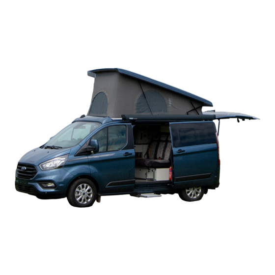
- Page 1 FORD TRANSIT CUSTOM AIR OWNER’S MANUAL...
-
Page 2: Table Of Contents
TABLE OF CONTENTS SECTION Introduction / Warranty / Body Construction ............. Campervan Code .......................... Preparing for the Road .......................... On the Road .......................... Arrival on Site .......................... Safety & Security .......................... Connection of Services .......................... Technical Specification .......................... Fitted Equipment .......................... - Page 3 Should you experience any difficulties contact your dealer who will be pleased to offer advice. Handbook To find your nearest Auto-Sleepers dealer please go to www.auto-sleepers.com. Any queries should be addressed to your Auto- Sleepers dealer.
- Page 4 Worcestershire them. WR12 7QF The dealer must then register the sale on the Tel: 01386 853 338 Auto-Sleepers warranty system to activate the Fax: 01386 858 343 cover. Email: aftersales@auto-sleepers.co.uk Web: www.auto-sleepers.co.uk Warranty Terms and Conditions...
-
Page 5: Campervan Code
CAMPERVAN CODE SECTION The Country and Coastal Codes Noise Upon arrival at your destination you should • Do not make excessive noise. be aware of the Country Code relating to • Children should be restrained from making campervan owners. This is entitled the Motor excessive noise. - Page 6 CAMPERVAN CODE SECTION Awnings and Tents that all passengers are seated in designated passenger seats and seat restraint straps Awnings and tents should only be used when worn. permission has been obtained. Before moving off, elevating roofs MUST be When on grass and staying for more than a lowered and correctly secured, and top hinged few days, the ground sheet and/or side flaps windows closed.
- Page 7 CAMPERVAN CODE SECTION • Take your litter home - it is unsightly and harmful to wildlife and the planet. • Help to keep all water clean. • Take special care of country roads. • Make no unnecessary noise. Most animals are very timid, noises can disturb them unnecessarily.
-
Page 8: Preparing For The Road
PREPARING FOR THE ROAD SECTION Your Campervan DO NOT EXCEED THE STATED MAXIMUM (Weights explained) LOAD. ITEMS FITTED OTHER THAN STANDARD EQUIPMENT WILL DEPLETE THE PAYLOAD Mass in Running Order (MIRO) STATED IN THIS HANDBOOK. The weight of your campervan as it leaves WARNING: Under no circumstances should the factory, as new with standard fixtures the maximum permissible laden mass of the... - Page 9 PREPARING FOR THE ROAD SECTION Before Moving Off 19. Referring to your base vehicle manual, check all fluid levels including automotive Whenever making a journey with your fuel and tyre pressures. Remember campervan, either setting off on holiday or to check that your spare tyre is at the returning home, it is good practice to run recommended pressure.
-
Page 10: On The Road
Carry out all manoeuvres as smoothly as • Please note that Auto-Sleepers advises possible. against the retrofitting of additional seat belts. Use nearside wing mirror to check campervan •... - Page 11 ON THE ROAD SECTION • Roof ventilators are closed and locked in the down position. • Top hinged windows are closed, and securely fastened. • Children do not roam around the vehicle; they may fall and injure themselves. Front Seat Swivel Your campervan is fitted with a swivel base to both of the front seats, so that they may be turned to face the rear of the vehicle.
- Page 12 ARRIVAL AT SITE SECTION Check Site Regulations Siting your Campervan When siting your campervan, keep to the roadways unless otherwise directed. Obey the road speed limit which, in general, is 10mph. Only a person in possession of a current driving licence is permitted to drive on the site. Stopping distances on grass are considerably greater than on tarmac.
-
Page 13: Safety & Security
Auto-Sleepers dealer. Please read the following carefully. In the interests of safety, replacement parts for appliances should conform to the appliance manufacturer’s specification and should be... - Page 14 SAFETY AND SECURITY SECTION Fire Extinguishers Under no circumstances must these vents be blocked or obstructed. It is recommended that a 1kg (2lb) minimum capacity dry powder fire extinguisher be Awnings located by the main exit door at all times. Campervan owners are advised to allow A pan fire should not have an extinguisher some fresh air circulation into the awning...
- Page 15 SAFETY AND SECURITY SECTION Electrical Systems SECURITY Batteries Chassis Number Battery terminals and connectors should Record the chassis number and the factory job be firmly attached. Battery surfaces number of your campervan, and keep them in should be free of moisture and dirt. a safe place at home.
- Page 16 CONNECTION OF SERVICES SECTION Water Systems To protect against damage as a result of freezing, drain the entire water system when Fresh/Waste Tanks there is danger of freezing conditions. The freshwater tank is located down the drivers side of the campervan. The freshwater tank is filled through the lockable cap located in the drivers stepwell.
-
Page 17: Connection Of Services
CONNECTION OF SERVICES SECTION LPG Re-fuelling General Information LPG re-filling is simple and efficient, carried out in much the same was as petrol and The vehicle is fitted with a 15ltr LPG Gas tank. diesel with a hose and nozzle designed to lock onto the filling connector on the The gas appliances in this vehicle are powered vehicle. - Page 18 CONNECTION OF SERVICES SECTION Note: For European touring, adapters for use with the UK bayonet filling connector may be used temporarily. • Refilling of portable LPG cylinders is not allowed. • All dispensing nozzles should be fitted with a nozzle shield. Please report to staff if missing.
- Page 19 CONNECTION OF SERVICES SECTION 1 - Gas Guard Nozzle Filling Instructions Ensure Gas Guard nozzles are fitted with protective nozzle shields. Report to site staff if missing. (Nozzle shields have been removed from pictures for clarity). (2) Pull back lever (4) Turn barrel anti Connecting Disconnect...
- Page 20 CONNECTION OF SERVICES SECTION GAS SAFETY ADVICE At periods not exceeding 10 years Facts about LPG This period is based on the date of manufacture (or previous test) marked on the • LPG is not poisonous. tank. The tank shall be: •...
- Page 21 CONNECTION OF SERVICES SECTION IN AN EMERGENCY In an emergency the gas supply to any of the the valve housing cover by releasing the black appliances can be cut-off by closing the red plastic clip. Then turn the large brass knob isolation taps located inside the vehicle, see clockwise to close the outlet valve.
- Page 22 CONNECTION OF SERVICES SECTION External BBQ Point 1. Push barbeque fitting into socket. 2. Turn red tap clockwise for gas flow. A Barbeque point is fitted to the vehicle. This is 3. To turn off, twist tap anti clockwise and push located by the side of the LPG filler.
- Page 23 CONNECTION OF SERVICES SECTION VENTILATION THERE IS NO DANGER WHEN ADEQUATE VENTILATION IS PROVIDED. General When you are cooking, it is essential to Fixed ventilation is a statutory requirement in provide additional ventilation such as opening all campervans. These ventilation apertures windows near the grill and hob.
- Page 24 CONNECTION OF SERVICES SECTION Connection • If any appliance is disconnected for repair, maintenance etc..., ensure Before turning on the gas supply, ensure that that the gas line is capped off. all gas operated equipment in the campervan • If taps are stiff to operate or appear is turned off.
- Page 25 CONNECTION OF SERVICES SECTION ELECTRICITY Note: Use mains cable fully uncoiled and As with electricity in the home, care must be protect from traffic. exercised when handling mains electricity. CAUTION: Be aware that the 12V appliances, Your attention is drawn to the following notice except the refrigerator, will not operate whilst as laid down by the institute of Electrical the ignition is switched on and the vehicle...
- Page 26 CONNECTION OF SERVICES SECTION The names and addresses of Approved Contractors in any locality (there are over The significance of REVERSE POLARITY 10,500 in the UK) can be obtained from: is that when equipment is switched off it may not be electrically isolated. NiCEIC Warwick House The only certain way of making...
-
Page 27: Technical Specification
Tyre Pressures DEFINITIONS The Auto-Sleepers conversion does not affect the tyre pressures in any way because the Maximum Technically Permissible completed vehicle is built within the maximum Laden Mass (MTPLM) capacities of the base vehicle. - Page 28 This must be subtracted from with European trailer braking legislation. the User Payload. MTPLM of the Axles Auto-Sleepers include the 230V connection cable and the habitation The individual axles also have MTPLM’s. battery in the mass in running order. The sum of the two axle MTPLM’s usually...
- Page 29 FITTED EQUIPMENT SECTION...
-
Page 30: Fitted Equipment
OR IF NOT FULLY EXTENDED, because then vehicle bodyside, consult your local dealer the lock is not working and the motor can be or the Auto-Sleepers Service Centre. damaged. CAUTION: In the event of the rear step being left extended, a buzzer, positioned behind the dashboard, will sound (when the ignition is switched on). - Page 31 FITTED EQUIPMENT SECTION EQUIPMENT ARRANGEMENT Lithium technology has many advantages over lead acid wet cell batteries such as: Ventilation • Lightweight, a 65AH battery weighs 7.2kg When the vehicle is being driven the roof • Built in battery management system (BMS) ventilators should be fully closed.
- Page 32 FITTED EQUIPMENT SECTION EC328 POWER CONTROL SYSTEM SYSTEM OVERVIEW Access to the electrical unit and fuses is only The following diagram shows the typical possible from the rear of the vehicle with the configuration of the EC328 system. The seat pushed into the fully forward position. key component is the EC328 power supply unit (PSU), which is the hub of the system Note: Ensure all the door catches are...
- Page 33 FITTED EQUIPMENT SECTION POWER SUPPLY DETAILS WARNING Under heavy loads the EC328PSU For the safe operation of all electrical equipment case may become hot. ALWAYS within your Leisure Vehicle it is important that you ensure the ventilation slots have read and fully understand these instructions. If a clear flow of air.
- Page 34 FITTED EQUIPMENT SECTION RESIDUAL CURRENT DEVICE & MINIATURE CIRCUIT BREAKERS The Residual Current Device (RDC) is basically provided to protect the user from lethal electric shock. The RCD will turn off (trip) if the current flowing in the live conductor does not fully return down the neutral conductor, i.e.
- Page 35 FITTED EQUIPMENT SECTION BATTERY CHARGER SOLAR PANEL CONVERTER The EC328 system incorporates an intelligent The EC328PSU incorporates a built-in dual channel three-stage battery charger / power converter. Solar Regulator that allows the direct connection of a 20 to 120W solar panel without the During stage 1 the battery voltage is increased need for additional components.
- Page 36 FITTED EQUIPMENT SECTION FUSES WARNING: When replacing fuses always replace a fuse with the correct value. NEVER replace with a higher value / rating as this could damage the wiring harness. If a replacement fuse ‘blows’ do not keep replacing the fuse as you could damage the wiring harness.
- Page 37 FITTED EQUIPMENT SECTION BATTERY A) Type / Selection For optimum performance and safety it is essential that only a proprietary brand LEISURE battery is used with a typical capacity of 60 to 120 Ah (Ampere / hours). A normal car battery is NOT suitable. This battery should always be connected when the system is in use.
- Page 38 FITTED EQUIPMENT SECTION C) Operation / Servicing Under normal circumstances it should not be necessary to remove the battery other than for routine inspection of the terminals and “topping up” of the battery fluid where applicable. Please see instructions supplied with the battery. Note: Do not over discharge the battery.
- Page 39 FITTED EQUIPMENT SECTION CONTROL PANEL DETAILS Layout and Buttons The following diagram shows the control panel layout and button functions. Note: to remove the decorative bezel, pull down and lift forward as indicated by the blue arrows. Item Function Options/Notes Use to turn the main leisure power on The adjacent LED is illuminated when Power ON / OFF...
- Page 40 FITTED EQUIPMENT SECTION Menu Functions - Reading Section Display Description Options/Notes The addition of a asterisk (*) in the top left of the display indicates that the alarm is set Main Control Panel display showing model number (EC328), software The addition of a hash (#) in version number (v2.1), specification the top right of the display (H), current time (12:00) and...
- Page 41 FITTED EQUIPMENT SECTION Display Description Options/Notes External temperature (in degrees centigrade) as measured by the external temperature probe Current (in Amps) being drawn from Negative figure (-) = current or charged into the selected being drawn from the selected battery* battery If a solar panel is fitted this display Positive figure = current being...
- Page 42 FITTED EQUIPMENT SECTION Menu Functions - Settings Section Display Description Options/Notes <INTERNAL> = The internal pump will be operated by the Shows the currently selected pump pump switch that will be operated by pressing the pump on / off switch (TAP symbol) <EXTERNAL>...
- Page 43 FITTED EQUIPMENT SECTION Display Description Options/Notes Access to set the event timer Press the select button () to select HOUR ON Use the up / down ( ) buttons to change Press the select button () to Please note the event timer uses a 24 select MINUTE ON hour cycle.
- Page 44 FITTED EQUIPMENT SECTION Warning Messages Display Description Options/Notes This WARNING display indicates that the Vehicle battery voltage is low (10.9 You can switch over to the volts or less). The panel will beep for Leisure battery immediately one minute and then switch over to (and cancel the beep) by using the Leisure battery to prevent draining the battery selector switch...
- Page 45 FITTED EQUIPMENT SECTION Common Fault Table Fault Possible Cause Proposed Fix Check and connect lead as per 5.1C Connecting lead between the site and Leisure Vehicle not connected Check also input connector at the base of the EC328PSU RCD switched off Reset RCD as per 5.1D Check supply polarity;...
- Page 46 FITTED EQUIPMENT SECTION Fault Possible Cause Proposed Fix Check batteries, turn EC328PSU charger switch on, and ensure mains supply is connected. Control Panel has no display Check control panel connecting lead at EC328PSU and behind Control Panel Contact your Dealer Battery save feature has operated to protect the Vehicle battery and or the Leisure battery.
- Page 47 FITTED EQUIPMENT SECTION Fault Possible Cause Proposed Fix No 230v supply Check all above Switch charger switch on (I) position, Charger not switched on switch will illuminate Battery not connected and Install charged battery / or charged Power switch on control Turn power on at control panel panel not switched to ON Recharge battery, check fuses, check...
- Page 48 FITTED EQUIPMENT SECTION Technical Data & Approvals Outline Specification INPUT 230v 230 Volts / 0 to 16 Amps + / - 10% RCD protected, 3 x MCB outputs of 10, OUTPUT 230v 10 and 6A via 2 x 9 way connector 2 x 20A battery inputs via a single 6 way INPUT 12v connector...
- Page 49 FITTED EQUIPMENT SECTION Approvals System: BSEN 1648-1, BSEN1648-2 compliant, BS7671: 2001 compliant Residual Current Device: RCD 40A 30mA trip to BS EN 61008 Miniature Circuit Breakers: MCB’s (10 & 6A) type C 6000A breaking capacity to BSEN 60898 Electro Magnetic Compatibility (EMC) directive 2004/108/EC Certificate CE20071224-1 Integrated Charger: BS EN 60335-1/2.29, 2006/95EC, IEC61000-3.2/3:1995, 1.
- Page 50 FITTED EQUIPMENT SECTION Electrical Connection B) Signal Input Connector Function Wire Colour Not used Not used Fresh sensor 75% (¾) full ORANGE Fresh sensor 25% (¼) full WHITE Fresh sensor 100% full GREEN Fresh sensor 50% (½) full BLUE Waste sensor 50% (½) full PURPLE / SLATE Waste sensor 100% full PURPLE / RED...
- Page 51 FITTED EQUIPMENT SECTION D) 12v Output Connector Function Fuse Wire Colour Ignitions YELLOW / GREEN Not Used Radio / Entertainment BLUE / YELLOW Internal Pump GREEN / BLUE External Pump GREEN / WHITE Rear Lights 1 PINK Rear Light 2 PINK Toilet Pump PURPLE...
- Page 52 FITTED EQUIPMENT SECTION F) 230v Mains output connector (2 off connectors wired identical) Function Wire Colour Live BROWN Earth GREEN / YELLOW Neutral BLUE Live BROWN Earth GREEN / YELLOW Neutral BLUE Live BROWN Earth GREEN / YELLOW Neutral BLUE While every effort has been made to ensure the accuracy and completeness of this document, no guarantee is given against errors or omissions.
- Page 53 FITTED EQUIPMENT SECTION Swivel Cab Seats The vehicle MUST be placed in Park (automatic) or in Gear (manual) and the handbrake lowered before swivelling driver/Passenger seat/s.
- Page 54 FITTED EQUIPMENT SECTION Tank Heaters Tank heater switches are located behind the drop down unit door. Heat pads are fitted to the Fresh and Waste water tanks and should only be used in cold weather conditions.
- Page 55 FITTED EQUIPMENT SECTION Wardrobe The wardrobe is equipped with a removable base panel for increased storage.
- Page 56 FITTED EQUIPMENT SECTION Gas Tank Isolation Switch The Gas Tank Isolation switch is located on the panel behind the drivers seat. This can be set to the “Off: position when no gas is required. The gas will automatically shut off when the vehicle ignition is activated.
- Page 57 FITTED EQUIPMENT SECTION The ventilation flap along the front of the roof canvas must be in the “open” position when using the vehicle for habitation purposes.
- Page 58 FITTED EQUIPMENT SECTION SCA Sleeping Roofs Opening the sleeping roof Note: Please make sure to open at least one door or window so that the air can escape when opening the roof. 1. Open the Velcro® fastener of the access cover above the cabin. 2.
- Page 59 FITTED EQUIPMENT SECTION 4. Release the locking of the roof according to the following four steps: 1) Put the turning handle of the locking upwards. 2) Release the locking in counterclockwise direction. 3) Fold the turning handle downwards. 4) Finally, the locking mechanism must be fixed at the magnet (marked in red in picture). These steps must always be executed at the driver’s side as well as the passenger’s side.
- Page 60 FITTED EQUIPMENT SECTION Closing the sleeping roof Note: Please make sure to open at least one door or window so that the air can escape when closing the roof. 1. Reel in the access cover (open the push button first). 2.
- Page 61 FITTED EQUIPMENT SECTION 3. Then, pull down the roof shell of the vehicle slowly (view onto the rear end). Note: Make sure that the tent fabric will not be jammed in this process. 4. After that, the sleeping roof will be locked according to the following four steps: 1) Fold the tent fabric up thoroughly in the area of the locking mechanism.
- Page 62 FITTED EQUIPMENT SECTION 6. Then fold up the remaining tent fabric thoroughly in the front area and fix it using the three intended Velcro® fasteners. 7. Close the Velcro® fastener of the access cover above the cabin. Note: Fix the access cover at the Velcro® fastener with a certain pretension. 8.
-
Page 63: Care Of Your Campervan
For deep gouge type Servicing of the conversion is the responsibility scratches, where the paint or gel may have of your local franchised Auto-Sleepers dealer been penetrated, you should first seek the whom all queries should be referred. Your local advice of your supplying Auto-Sleepers dealer. - Page 64 CARE OF YOUR CAMPERVAN SECTION UPHOLSTERY MAINTENANCE Work Surfaces Cleaning Whilst these are wearing, hot pans should not be placed directly on these Upholstery should be brushed or surfaces, since damage may result. vacuumed regularly. Fabrics should be wiped every six to eight weeks with a STAINLESS STEEL COMPONENTS lint free cloth and fabric cleaning fluid.
- Page 65 CARE OF YOUR CAMPERVAN SECTION WATER SYSTEM fresh water tank and waste water tank left in the open position. Likewise, all internal Fresh Water Tank taps should be left open and the water pump run until the last traces of water have come At regular intervals, and at least every out of the taps.
- Page 66 CARE OF YOUR CAMPERVAN SECTION Exterior Fit, where appropriate, winter covers to the fridge ventilator grilles. Give your Auto-Sleeper a good wash and polish before laying up, and apply a small film of protective oil to the stainless steel roof rack, ladder and any other external polished metal components.
- Page 67 MCB tripped out, the fault must be located before replacing the fuse. If a fault is suspected with the LPG system, consult a GAS SAFE registered technician. If in doubt consult a qualified technician or your local Auto-Sleepers dealer. 12V TROUBLESHOOTING CHART...
- Page 68 CARE OF YOUR CAMPERVAN SECTION Symptom Cause Remedy Find fault and replace fuse with same Fuse blown rating Heater not operating/cuts Low battery charge Recharge battery Unit fault Refer to dealer Find fault and replace fuse with same Fuse blown rating Cooker Ignition not operating Spark unit fault...
- Page 69 CARE OF YOUR CAMPERVAN SECTION LPG TROUBLESHOOTING CHART Symptom Cause Remedy No gas Check isolation valve is open Appliance will not light Low battery (auto ignition) Charge battery Appliance lights but goes Flame supervision device out immediately the FSD (FSD) is not functioning Refer to dealer override is released correctly...
- Page 70 CARE OF YOUR CAMPERVAN SECTION WATER TROUBLESHOOTING CHART Symptom Cause Remedy No water Fill tank Continuous running of water Major leak Switch off immediately and check system pump Pressure not set correctly Adjust as page 7-1 Intermittent operation of Minor leak in water system Check push fit joints water pump Water pump does not...
- Page 71 We suggest that you record key details in the spaces below should you accidentally mislay your keys or other vital documentation. Vehicle Type ....................................Vehicle Model ....................................Auto-Sleepers Production Number ............................. Keys ....................................Ignition Key ....................................Door Key (if applicable) ................................
- Page 72 CARE OF YOUR CAMPERVAN SECTION RECOMMENDED ANNUAL SERVICE CHECK Check for good weather seal when FOR CAMPERVAN CONVERSIONS window is closed and latched. It is recommended that the annual service Check catches and stays for is carried out by an approved campervan satisfactory operation.
-
Page 73: Service Details
SERVICE DETAILS SECTION INTERNAL ATTACHMENTS TO CHASSIS OR UNDERBODY Body Seepage Check Folding/Retractable Steps Examine for moisture/water staining of Check that step pivots are satisfactory areas under windows, at side of roof and and not worn. Check that, when closed, at corners, which could indicate water the retaining mechanism holds the step seepage problems, A moisture meter... - Page 74 SERVICE DETAILS SECTION ELEVATING ROOFS WATER SYSTEM Lifting Mechanism Before operating the water system, a Gas struts or spring nuts should be checked visual check of the following items may for corrosion (particularly on the piston show up an obvious leak source: rods of gas struts), smooth operation when operating roof up and down and to ensure Fresh Water Tank...
- Page 75 NICEIC (National inspection Council for Electrical Installation Contracting) or a member of the Electrical Contractors Association. AUTO-SLEEPERS SERVICE CENTRE ANNUAL HABITATION CHECK Introduction It is recommended that every 12 months the habitation side of your campervan is inspected by qualified technicians.
- Page 76 SERVICE DETAILS SECTION CAMPERVAN HABITATION SERVICE CHECK SHEET Vehicle Registration Mark A Class Make & Model Coachbuilt Year of Manufacture High top conversion Recorded Mileage Elevating Roof Dismountable CHECK ITEM Manual Remarks - Advice to Customers SECTION 1: BODY MOUNTING BODY TO CHASSIS BODY TO CAB BODY RETENTION...
- Page 77 SERVICE DETAILS SECTION CHECK ITEM Manual Remarks - Advice to Customers SECTION 7: LIFT UP ROOFS LIFTING MECHANISM CANVAS SIDE WALLS SOLID SIDE WALLS LOCKING SECTION 8: GAS SYSTEM CYLINDERS & REGULATOR HOSE & PIPING APPLIANCES SECTION 9: WATER SYSTEM FRESH WATER TANK WASTE WATER TANK FILTER PUMP...
- Page 78 SERVICE DETAILS SECTION...
- Page 79 SERVICE DETAILS SECTION...
- Page 80 SERVICE DETAILS SECTION...
Need help?
Do you have a question about the FORD TRANSIT CUSTOM AIR 2022 and is the answer not in the manual?
Questions and answers