Table of Contents
Advertisement
Quick Links
Use and Safety Manual
Original instruction
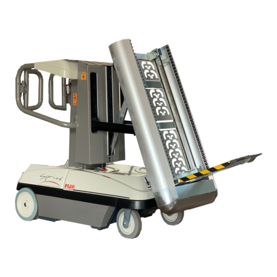
Industrial Truck Stock-picker
Model
Model
LUI MINI T.L.
LUI MINI TLP
(SPRINT Tire Lift)
(SPRINT Tire Lift)
Always keep this manual in the machine manual box
English Rev01_21 _Australian
Braviisol Divisione Meccanica s.r.l.
S.S. 16 Adriatica km. 314,600
60022 Castelfidardo (AN)- Italy
Tel. 0039.071.7819090
Fax 0039.071.7819355
www.bravi-platforms.com
www.bravi-parts.com
Advertisement
Table of Contents

Related Manuals for Bravi Platforms SPRINT LUI MINI T.L.


Summary of Contents for Bravi Platforms SPRINT LUI MINI T.L.
- Page 1 Use and Safety Manual Original instruction Industrial Truck Stock-picker Model Model LUI MINI T.L. LUI MINI TLP (SPRINT Tire Lift) (SPRINT Tire Lift) Always keep this manual in the machine manual box English Rev01_21 _Australian Braviisol Divisione Meccanica s.r.l. S.S. 16 Adriatica km. 314,600 60022 Castelfidardo (AN)- Italy Tel.
- Page 2 INTRODUCTION For: This manual is an extremely important element. Always keep it stored on the WARNING machine. • Accident notification • Publications relating to the safety of The purpose of this manual is to illustrate, for the owner, users, operators, THIS PRODUCT MUST CONFORM TO the product firms offering leasing and those subjects receiving leasing of the machine, the...
-
Page 3: Section 1. Safety Precautions
SECTION 1. SAFETY PRECAUTIONS Machine inspection 1.1 GENERAL INFORMATION • Use the machine only after having carried out the functional This section illustrates the precautions necessary for the correct and safe use and inspection checks and verifications. For further indications, maintenance of the machine. -
Page 4: Operation
SECTION 1. SAFETY PRECAUTIONS .3 OPERATION .4 RISK OF FALLING General information • • Use the machine exclusively for transport of personnel for Before using the machine, make sure that all of the safety the manual handling of tires. railings and gates are attached in their correct positions. •... -
Page 5: Electrocution Hazard
SECTION 1. SAFETY PRECAUTIONS 1.5 ELECTROCUTION HAZARD 1.6 TOPPLING HAZARD The machine is not electrically insulated. Maintain a distance of at least 3 metres (10 feet) between any part of the ma- chine and its occupant and an electrical power line or piece of equipment with an electrical charge rated at least 50,000 Volts. -
Page 6: Lifting And Transport
SECTION 1. SAFETY PRECAUTIONS 1.7 CRUSHING AND IMPACT HAZARDS 1.8 LIFTING AND TRANSPORT • General information All personnel, whether operational or on the ground, must wear the personal safety equipment required by the regulations in force or by • the risk analysis performed in the workplace. During lifting and transport, personnel are prohibited from standing •... -
Page 7: Section 2. Preparation And Inspection
SECTION 2. PREPARATION AND INSPECTION 2.1 PERSONNEL TRAINING 2.2 PREPARATION INSPECTION AND MAINTENANCE The machine is a personnel transport device for manual tire picking BRAVIISOL provides information relative to machine inspection, indicated in operation. the following table 2.3 on page 14. Therefore, it is to be used and maintained exclusively by trained and For further information regarding the machine, consult local regulations. - Page 8 SECTION 2. PREPARATION AND INSPECTION NOTE: 2.4 COMPLETE DAILY INSPECTION Check the level of the hydraulic oil with the ma- chine having the basket lowered, from the sight WARNING glass found under the cover. If necessary, top up with a mineral oil with a viscosity index of 22 (for climactic conditions with very cold temperatures, TO AVOID POSSIBLE INJURIES, MAKE SURE THAT THE ELECTRICAL that is, below -20°C, the use of mineral oil with a...
-
Page 9: Before Every Use
SECTION 2. PREPARATION AND INSPECTION 2.5 BEFORE EVERY USE 2.6 FUNCTIONAL VERIFICATIONS • Make sure that all of the manuals are in their weather resistant At the end of the “complete inspection”, carry out a functional verification of all manual box on board the machine. of the systems in an area that is free of super-elevated or ground level obsta- •... -
Page 10: Section 3. Operation Of The Machine
SECTION 2. SECTION 3. PREPARATION AND INSPECTION OPERATION OF THE MACHINE Slope alarm limit: with the platform completely lowered, drive the vehicle on a slope greater than 1.5° in any direction (not exceeding THE MANUFACTURER HAS NO DIRECT CONTROL WHATSOEVER ON its nominal operational capacity on a grade). -
Page 11: Function Of The Machine
SECTION 3. OPERATION OF THE MACHINE 3.3 FUNCTION OF THE MACHINE Preliminary Operations Before activating the machine using the commands on the ground station panel or those on the platform, it is necessary to satisfy the following com- mand conditions. •... -
Page 12: Battery Charging
SECTION 3. OPERATION OF THE MACHINE 3.4 FRONT CANOPY 3.5 BATTERY CHARGING Removal Battery low voltage alarm warning light 1. Lift the canopy in correspondence to the back part (column) so as to In the command panels on the platform and the ground station have indica- free bumper on the base frame. - Page 13 SECTION 3. OPERATION OF THE MACHINE 3.6 PLATFORM COMMAND CONSOLE OPERATION 3.6.1 LUI MINI T.L. - TLP A - A.C. POWER INPUT FOR THE BATTERY CHARGER B - CHARGE STATUS FOR THE BATTERY CHARGER The LED’s battery charge status for the batteries are located near the AC power input on the chassis.
- Page 14 SECTION 3. OPERATION OF THE MACHINE General Information Throttle Handle Before activating the machine by way of the commands on the ground or Grasp the handle in the right hand and those on the platform, it is necessary to satisfy the following command condi- tions: ROTATE the handle FORWARD (back of the •...
- Page 15 SECTION 3. OPERATION OF THE MACHINE Acoustic Signal Device Button Steering Rocker Switch When the machine is turned on, the pressure on this button determines the The Steering has been designed to be easily activated with the left activation of the horn. hand.
- Page 16 SECTION 3. OPERATION OF THE MACHINE Footswitches Basket Control Station DO NOT PLACE THE FOOT ON THE FOOT SWITCHES BEFORE At power-up and during operation the battery gauge display shows TURNING THE KEY SELECTOR FROM “0” TO “1” OR “2” the current machine operating status.
- Page 17 SECTION 3. OPERATION OF THE MACHINE Tire Lift compartment Raising/Lowering Buttons The functionality of these buttons is available only if the operator has his or her hells on the footswitches in the platform . ATTENTION Push and hold down the Tire Lift compartment Raising Button ( Button 8 ) to acti- vate the electrical raising of the Tire Lift compartment that from a vertical position Distribute tires only on the lift compartment doing this without loading and unload- will turn in an horizontal position.
- Page 18 SECTION 3. OPERATION OF THE MACHINE Tire Lift compartment Rolling Buttons The functionality of these buttons is available only if the operator has his or her Push and hold down the Tire Lift compartment Lowering Button ( Button 9 ) to hells on the footswitches in the platform .
- Page 19 SECTION 3. OPERATION OF THE MACHINE Tire Lift compartment Microswitches The Tire Lift compartment is equipped with two limit switches one in the bottom Push and hold down the Tire Lift Roll Out Button ( Button 10 ) to activate the part and one in the upper part of the device that stop the roll in and roll out of the electrical roll out of the tire away from the operator in order to pick down tires to loading shelf as soon as they are closed.
- Page 20 SECTION 3. OPERATION OF THE MACHINE 3.7 GROUND COMMAND PANEL Emergency stop button Pushed immediately stops all the operational phases of the machine. Reset DOES NOT actuate the machine, but enable the command devices. Display This is the principle control display system on the machine: •...
- Page 21 SECTION 3. OPERATION OF THE MACHINE Ground Control Station • Pushing and keep pushed both buttons, left and right arrows, At power-up and during operation the LCD display on the ground Control Mod- SIMULTANEOUSLY activates the release of the brakes. ule displays the current machine operating status.
-
Page 22: Platform Configuration
SECTION 3. OPERATION OF THE MACHINE 3.8 MANUAL DESCENDING EMERGENCY LEVER 3.9 PLATFORM CONFIGURATION ATTENTION Platform Maximum Load Capacity CRUSHING HAZARD During the following operations and after having performed all of the procedures for the emergency descent, the operator must pay great attention to leaving the area and making sure that no other person, animal or thing is within range or may come into range of the movement for a distance of at least 2 metres (6.56ft) and above all that there are no other obstacles... - Page 23 SECTION 3. OPERATION OF THE MACHINE 3.11 TRANSPORT PROCEDURES 3.12 PROPERLY PLACING THE MACHINE ON PALLET HOISTING AND TIE DOWN To safely move the machi- General Information ne, it has to be properly placed on a pallet and The LUI MINI T.L. - TLP. may be transported to the workplace with one wrapped in a plastic strap of the methods described below: as in the picture.
-
Page 24: Section 4. Emergency Procedures
SECTION 5. GENERAL TECHNICAL SPECIFICATIONS SECTION 4. AND OPERATOR MAINTENANCE EMERGENCY PROCEDURES 4.1 EMERGENCY FUNCTIONS 5.1 INTRODUCTION Operator not capable of controlling the machine This section of the manual provides further information necessary for the operator so that he or she may tend to the proper operation CONDITION IN WHICH THE OPERATOR OF THE PLATFORM IS of the machine and relative maintenance. - Page 25 SECTION 5. GENERAL TECHNICAL SPECIFICATIONS AND OPERATOR MAINTENANCE...
-
Page 26: Power Supply
SECTION 5. GENERAL TECHNICAL SPECIFICATIONS AND OPERATOR MAINTENANCE TECHNICAL SPECIFICATIONS LUI MINI T.L. - Operational height 17.55 ft/535 cm Machine Height with Tire Lift device in upper Maximum speed 3.1 mph - 5 Km/h position Turning Radius (Internal) ZERO (Platform Completely Extended) 17ft/520cm Maximum Slope Practicable T.L. - Page 27 SECTION 5. GENERAL TECHNICAL SPECIFICATIONS AND OPERATOR MAINTENANCE 5.2 Weight of the Machine Components 5.3 MAINTENANCE TO BE PERFORMED BY THE OPERATOR COMPONENT WEIGHT 5.3.1 Hydraulic oil top up 66.13 lb each/30 kg 1pcs - Batteries The level of the hydraulic oil is to be checked with the machine having 264.55 lb total/120 kg total the basket lowered, from the sight glass found under the cover.
-
Page 28: Section 6. Inspection And Repair Log
SECTION 5. SECTION 6. GENERAL TECHNICAL SPECIFICATIONS INSPECTION AND REPAIR LOG AND OPERATOR MAINTENANCE PRELIMINARY INSPECTIONS BEFORE START UP CHECK-LIST • Dry the terminal connectors well • Put the connectors back in their place, pay- MODEL______________________ ing close attention to the correct positive/ negative pole connection, then tighten well. -
Page 29: Daily Inspection Checklist
DAILY INSPECTION ANNUAL INSPECTION CHECK-LIST CHECK-LIST MODEL______________________ SERIAL NUMBER______________ YEAR OF MANUFACTURE_________ Date: Dealer: Serial Number: Address: Make sure that all of the manuals are in their weather resistant container on Model: City/State/ZIP code: board the machine. Date last inspection : Phone: Make sure that the tag with the serial number of the platform as well as all of Date placed into Service... -
Page 30: Section 7. Error Codes
SECTION 7. ERROR CODES 7.1 LUI MINI T.L. - TLP ERROR ERROR DECRIPTION CODE DECRIPTION CODE FAULT: BAD P/N FAULT: BAD INTERNAL 5V NOT CALIBRATED FAULT: BAD TILT SENSOR HEIGHT NOT CALIBRATED FAULT: BAD INTERNAL SLAVE FUNCTIONS LOCKED - NOT CALIBRATED FUNCTIONS LOCKED - TEST MODE SELECTED FUNCTIONS LOCKED - TOO HOT FUNCTIONS LOCKED - POTHOLE... -
Page 31: Section 8 Technical Annexes
SECTION 8 TECHNICAL ANNEXES 8.1 HYDRAULIC SCHEME LUI MINI T.L. - TLP... - Page 32 SECTION 8 TECHNICAL ANNEXES 8.2 WIRING DIAGRAM LUI MINI T.L. - TLP...
- Page 33 SECTION 8 TECHNICAL ANNEXES 8.2 WIRING DIAGRAM LUI MINI T.L. - TLP...
- Page 34 SECTION 8 TECHNICAL ANNEXES 8.2 WIRING DIAGRAM LUI MINI T.L. - TLP...
- Page 35 SECTION 8 TECHNICAL ANNEXES 8.2 WIRING DIAGRAM LUI MINI T.L. - TLP...
- Page 36 SECTION 8 TECHNICAL ANNEXES 8.2 WIRING DIAGRAM LUI MINI T.L. - TLP TS100 PIN DESCRIPTION INPUT CAN TILLER DESCRIPTION INPUT PCAN-1 CAN1H TO CAN DISPLAY MODULE (Plat) P10-3 ana 1 Accelerator PCAN-2 CAN1L TO CAN DISPLAY MODULE (Plat) P10-4 ana 2 Steer PCAN-3 Shield...
- Page 38 LIMITED WARRANTY—Warranty Statement PROCEDURE OF THE WORKS COVERED BY THE WARRANTY: IF THE WARRANTY IS NOT INCLUDED IN THE SALES CONTRACT, THE FOL- The manufacturer must be notified of all claims covered by the warranty within 48 LOWING GUIDELINES APPLY TO THE MACHINE WARRANTY. hours of the anomaly, in writing or by fax (not only verbally) and as detailed as possi- ble.
- Page 39 BRAVIISOL Divisione Meccanica S.r.l. S.S. 16 Adriatica km. 314,600 60022 Castelfidardo (AN) Tel. 071.7819090 Fax 071.7819355 E-mail: info@bravi-platforms.com Website: www.bravi-platforms.com Spare parts: www.bravi-parts.com...
Need help?
Do you have a question about the SPRINT LUI MINI T.L. and is the answer not in the manual?
Questions and answers