Table of Contents
Troubleshooting

Subscribe to Our Youtube Channel
Related Manuals for Apex Digital Sturdy SA-260MB


Summary of Contents for Apex Digital Sturdy SA-260MB
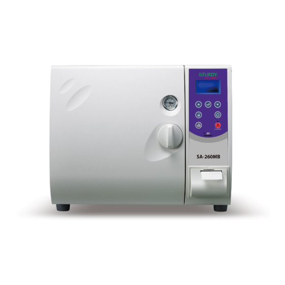
- Page 1 “ ” “ ” SA-260MB Instruction Manual Please read manual carefully before using and keep it well for future reference.
-
Page 2: Table Of Contents
Contents 1. Important Safety Instructions ....................1 2. Explanation of Safety Symbols and Notes ................9 3. Unpacking ..........................10 4. Installation ..........................11 4.1 Environment ........................11 4.2 Install the Sterilizer ......................11 5. Introduction ..........................18 5.1 Intended Use ........................ 18 5.2 Description of the Sterilizer ................... - Page 3 6.14 Description of Printer ....................86 6.14.1 Dimensions of Printer Paper ................86 6.14.2 Installation of Printer Paper ................86 6.14.2.1 Automatic Feeding Paper ............... 86 6.14.2.2 Manual Feeding Paper ................89 6.14.3 Printout of Printer ....................92 6.14.3.1 Printout of General Program ..............92 6.14.3.2 Printout of LIQUID Program(Optional) ............
- Page 4 11. Specifications ........................128...
-
Page 5: Important Safety Instructions
1. Important Safety Instructions CAUTION: Please install, operate and maintain the sterilizer in accordance with this Instruction Manual. Failure to do so could result in serious injury or damage to the unit. Please read manual. Figure 1 WARNING: DO NOT place alcohol or other flammable items in the sterilizer. An explosion could occur, causing personal injury. - Page 6 Figure 3 WARNING: Always check the status of the electric wire; unplug the power cord if breakage comes up. Contact your supplier for service support. Check Electric wire Figure 4 WARNING: Children are not allowed to use or play with the unit. Figure 5...
- Page 7 WARNING: Do not put your fingers into the gap on the hinged side of the door. Figure 6 WARNING: Always check the pressure gauge before opening the door. DO NOT attempt to open the door if the pressure is not at zero (0). Check Pressure at “ZERO”...
- Page 8 WARNING: Use sterilization indicator test strips to check that sterilization has been successful. Figure 9 WARNING: Contact your supplier for service support if the safety valve is active for releasing the over-pressure Please call service supplier Figure 10 WARNING: Use water for sterilization or distilled water. Normal tap water contains minerals, especially chlorides, which have corrosive effects on stainless steel.
- Page 9 CAUTION: Do not put objects on the power plug or power cord. Figure 12 CAUTION: The outer casing and metal surfaces of the sterilizer are hot during operation, please do not touch it. Figure 13 WARNING: DO NOT place any objects on the water reservoir of the sterilizer. Figure 14...
- Page 10 CAUTION: Do not overfill the water reservoir. The water level must be maintained between the Full and Minimum labels on the right hand side of the sterilizer. Figure 15 WARNING: Steam and hot water may be present when opening the door after a sterilizer cycle.
- Page 11 CAUTION: Do not tip over the unit or allow it to fall on the power plug. Figure 18 CAUTION: It will require at least two (2) or more people to carry the sterilizer to avoid dropping it off by mistake. Figure 19 CAUTION: Always allow a minimum of 20 minutes between each sterilization cycle.
- Page 12 CAUTION: Please unplug the power cord and drain off water from the reservoir if the sterilizer will not be used regularly. Figure 21 CAUTION: Always keep the sterilizer clean. Figure 22 WARNING: The door must be closed completely during operation of the unit. If the “Error No.
-
Page 13: Explanation Of Safety Symbols And Notes
2. Explanation of Safety Symbols and Notes Caution, consult instruction manual for use Protective earth (ground) Alternating Current Attention! Hot surface Disposal of Electrical & Electronic Equipment (WEEE): This product should be handed over to an applicable collection point for the recycling of electrical and electronic equipment. -
Page 14: Unpacking
3. Unpacking CAUTION: It will require at least two (2) or more people to carry the sterilizer to avoid dropping it off by mistake. Wall Base Figure 23 – Unpacking Cut the banding Lift off the top cover of the carton Remove the wall and the foam packaging inserts Carefully lift the sterilizer from the packaging base Check all accessories are present as follows (accessories are packed inside the sterilizer... -
Page 15: Installation
4. Installation 4.1 Environment This equipment has been designed for use in accordance with the International EMC (Electromagnetic Compatibility) Standards. In view of different environments, please follow the instructions given below to eliminate interference, if necessary. Move the equipment or rotate its direction; Enlarge the space between the equipment and other machines;... - Page 16 Open the water reservoir cap; pour water for sterilization or distilled water into the water reservoir as shown in Figure 24 Water Reservoir Cap Water Level Figure 24 CAUTION: Please fill Water for Sterilization or Distilled Water Only into the sterilizer. Please do not fill water over the yellow water level mark as shown in Figure 25 and Figure 37 –...
- Page 17 Water Inlet Figure 26 C. How to set the ” Auto add water”: Select ”system setting” as shown in Figure 27 (Refer to “6.8.4” for detail operation.) MENU Unwrapped 121℃ Wrapped 121℃ Unwrapped 134℃ Wrapped 134℃ Flash PRION LIQUID Customization Function Test System Setting Figure 27...
- Page 18 and then select ”Auto add water” as shown in Figure 28 System set Date and Time Language Unit Print Auto add Water Cycle counter Serial Number Calibration Figure 28 set to ”ON” as shown in Figure 29. Auto add Water Auto add Water Figure 29 D.
- Page 19 Install the heater cover to the chamber as shown in Figure 31 (standard accessory) Ensure the rounded edge is towards the back and the vertical front edge of the cover locates securely into the corresponding slots in the lower part of the chamber opening. Heater Cover Chamber Water Stopper...
- Page 20 G. Install the tray as shown in Figure 33. (standard accessory) Tray Frame Tray Heater Cover Figure 33 – Tray H. Install the Sterilization Box as shown in Figure 34. (optional accessory) Sterilization Box Heater Cover Figure 34 – Sterilization Box The maximum useable space is 7.5L which is 156 mm (W) x 132.5 mm(D) x 356 mm(H).
- Page 21 Close the door and turn the knob clockwise 90°in order to lock it 100%. Figure 36 WARNING: Please make sure to turn the knob 90 degrees completely, so the door lock will be closed automatically to avoid any problems on security. Ensure the Power Switch is in OFF “O”...
-
Page 22: Introduction
5. Introduction 5.1 Intended Use This product is a tabletop high pressure steam sterilizer which is designed and developed for the sterilization of wrapped and unwrapped items. Suitable loads are those included in EN 13060 such as solid, porous, hollow loads type A, hollow loads type B;... -
Page 23: Internal Configuration
Maintenance Cover Exhaust Hose / Water Level Indicator Power Cord Figure 39 – Bottom View 5.2.2 Internal Configuration Temperature Sensor Over temperature controller Exhaust Heater Water Stopper Water Level Sensor Figure 40 – Inside of Chamber... -
Page 24: Control Panel
5.2.3 Control Panel Up button: LCD Panel: Used for setting Display the and changing the information of function and sterilization increasing the status. parameters. Enter Button: Press this button to execute or confirm the input Unlock button: data. Press this button to release the Down button: lock status after... -
Page 25: Operation
6. Operation The “Table 1” describes the build-in programs that can be used by the sterilizer model SA-260MB. Table 1 - Sterilization cycle Cycle Program Description UNWRAPPED 121ºC Applicable to solid, porous, hollow loads type A, hollow loads type WARAPPED 121ºC B;... - Page 26 Cycle Program Description PRION Applicable to solid, porous, hollow loads type A, hollow loads type B; both single wrapped and double wrapped, and unwrapped loads. Vacuum step with 4 vacuum pulses, Sterilization temp 134ºC, Sterilization time 18 minutes, Dry time 30 minutes. Refer to “6.8 PRION Sterilization Program”...
- Page 27 Cycle Program Description Customization This function allows the operator to define special sterilization cycle (such as temperature and time) within the specification of this autoclave. Parameters that can be adjusted: Optional Vacuum step: Yes or No, Sterilization temp: 105-135ºC, Sterilization time: 0-60 minutes 59 seconds, Dry time: 0-60 minutes.
- Page 28 Holding time (Sterilization) 121ºC/134º 121°C or 134°C 119°C Exhaust Time Ambient Temp °C 0 bar -.0.35 bar -0.80 bar Drying Pre-Vacuum Heating Up Temp. / Pressure Figure 42 Legend of each cycle: Table 2 T0-T1,T2-T3,T4-T5,T6-T7 PV1- PV4 Vacuum stage (Air removal stage) T1-T2,T3-T4,T5-T6,T7-T8 H1-H4 Heating stage...
- Page 29 Maximum load of each build-in program: Table 4 Program Unwrapped Unwrapped Wrapped Wrapped PRION Flash LIQUID Customization 121ºC 134ºC 121ºC 134ºC Temperature 105-135 105-135 (ºC) Pressure (bar) -0.8 Sterilization time minutes) 1-60 Dry time (minutes) 1-60 Total time (minutes) 137-182 1-60 20-160 Solid unwrapped (kg)
- Page 30 Function test program: Table 5 Test program Air leakage Helix B&D TEST TEST TEST Temperature (ºC) Pressure (bar) -0.8 Sterilization time (minutes) Dry time (minutes) Total time (minutes) Type of load Empty chamber Test tool...
-
Page 31: Flow Chart With Build-In Program
6.1 Flow Chart with Build-in Program Locate the sterilization items and close door; insert a SD card. Test Program Standard Sterilization Program 1) Leakage Test 1) Unwrapped / Wrapped 121°C 2) Unwrapped / Wrapped 134°C 2) Helix Test 3) PRION 3) B&D Test Leakage Program... -
Page 32: Flow Chart With Flash Program(Optional)
6.2 Flow Chart with Flash Program(Optional) Locate the sterilization items and close door; insert a SD card. Flash Sterilization Program Flash Press “Enter” Button to star vacuum Add Water and Heating Vacuum pump operated start from 119 °C until -35kPa, and repeat this vacuum for 1 times. -
Page 33: Flow Chart With Liquid Program(Optional)
6.3 Flow Chart with LIQUID Program(Optional) Locate the sterilization items and close door; insert a SD card. LIQUID(Optional) Setting Sterilization Temp: 110-135 ºC Sterilization time:1- 60 min Press “Enter” Button to star vacuum Add Water and Heating Equilibrium Time Sterilization Cooling Down Cycle Complete Storing data on to SD card, and printing data... -
Page 34: Flow Chart With Customization Program
6.4 Flow Chart with Customization Program Locate the sterilization items and close door; insert a SD card. Dry only Customization Setting Without Pre-vacuum With Pre-vacuum Sterilization Temp: Sterilization Temp: Dry time: 1-60 105-135 119-135°C Sterilization time:0- 60 Sterilization time:0- 60 min min 59 seconds 59 seconds Dry time: 0-60 min... -
Page 35: Prepare Sterilization
6.5 Prepare Sterilization Follow “4.2 Install the Sterilizer” to finish installation first. Follow “4.2 Install the Sterilizer A” to make sure the water inside reservoir is sufficient. C. Press the “POWER” switch to ON “I” position. D. Check the Pressure Gauge is reading ZERO, and then press the “unlock button” open the door by turning the door knob 90°... -
Page 36: Standard Sterilization Program
6.6 Standard Sterilization Program Before start Sterilization program please refer to “6.5 Prepare Sterilization” section. How to set the Standard Sterilization program: Holding time (Sterilization) 121ºC/134ºC 121°C or 134°C 119°C Exhaust Time Ambient Temp °C 0 bar -.0.35 bar -0.80 bar Drying Pre-Vacuum Heating Up... - Page 37 MENU Unwrapped 121ºC Wrapped 121ºC Unwrapped 134ºC Wrapped 134ºC Flash PRION LIQUID Customization Function Test System Setting Figure 48 Unwrapped 121ºC Pre-Vacuum Ster. Temp: 121ºC Ster. Time: 15 m00s DryTime:15m Figure 49 Wrapped 134ºC Pre-Vacuum Ster. Temp: 134ºC Ster. Time: 15 m00s DryTime:30m Figure 50 D.
- Page 38 Press button again to star the selected program. The relative information such as program cycle, present process, temperature, pressure and time as shown in Figure 51 or Figure 52 will be displayed on the panel. Program Unwrapped 121ºC Present Process:PV1 Process Real Chamber Temperature 35.0ºC...
-
Page 39: Flash Sterilization Program
6.7 Flash Sterilization Program Before start Sterilization program please refer to “6.5 Prepare Sterilization” section. How to set the Standard Sterilization program: Holding time (Sterilization) 134ºC 134°C 119°C Exhaust Time Ambient Temp °C 0 bar -.0.35 bar -0.80 bar Pre-Vacuum Heating Up Temp. - Page 40 Flash Pre-Vacuum Ster. Temp: 134ºC Ster. Time: 3 m30s Figure 56 D. Parameters of the programs: Table 7 Flash Sterilization 134 ºC Temperature Sterilization 3 min 30 sec Time Press button again to star the selected program. The relative information such as program cycle, present process, temperature, pressure and time as shown in Figure 57 will be displayed on the panel.
- Page 41 G. When press the button to open the door, a “Mind The Steam” will be prompted and then followed by “Please Open The Door.” message. Open the door and take out the sterilized items. Check the status of the indicators. If failed, repeat the cycle. Consult with the qualified technician for calibration if necessary.
-
Page 42: Prion Sterilization Program
6.8 PRION Sterilization Program Before start Sterilization program please refer to “6.5 Prepare Sterilization” section. How to set the PRION Sterilization program: Holding time (Sterilization) 134ºC 134°C 119°C Exhaust Time Ambient Temp °C 0 bar -.0.35 bar -0.80 bar Drying Pre-Vacuum Heating Up Temp. - Page 43 PRION Pre-Vacuum Ster. Temp: 134ºC Ster. Time: 18 m00s DryTime:30m Figure 61 D. Parameters of the PRION programs: Table 8 PRION Sterilization 134 ºC Temperature Sterilization 18 min. Time Dry Time 30 min. Press button again to star the selected program. The relative information such as program cycle, present process, temperature, pressure and time as shown in Figure 62 will be displayed on the panel.
- Page 44 G. When press the button to open the door, a “Mind The Steam” will be prompted and then followed by “Please Open The Door.” message. Open the door and take out the sterilized items. Check the status of the indicators. If failed, repeat the cycle. Consult with the qualified technician for calibration if necessary.
-
Page 45: Liquid Program(Optional)
6.9 LIQUID Program(Optional) WARNING: This is not a CE declared program and validation of sterility when using this program is the responsibility of the user. WARNING: Users who define the parameters should take their own responsibilities and obligations to undertaken the risk of sterilization uncertainty. Before start Sterilization program please refer to “6.5 Prepare Sterilization”... - Page 46 LIQUID Sterilization temperature Ster. Temp: 121ºC Sterilizationtime Ster. Time: 10m Statr Figure 66 D. Press button to move the cursor to the “Ster. Temp”. Press button to enter editing mode, and then press button to change sterilization temperature. Press button to store sterilization temperature parameter as shown in Figure 67. LIQUID Sterilization Ster.
- Page 47 Parameters of the LIQUID programs: Table 9 LIQUID Range of Sterilization Temperature 110 - 135 ºC Range of Sterilization Time 1 - 60 minutes G. Press button until as shown in Figure 69. LIQUID Ster. Temp: 121ºC Ster. Time: 15 m Figure 69 H.
- Page 48 When press the button to open the door, a “Mind The Steam” will be prompted and then followed by “Please Open The Door.” message. Open the door and take out the sterilized items. Check the status of the indicators. If failed, repeat the cycle. Consult with the qualified technician for calibration if necessary.
-
Page 49: Dry Program
6.10 Dry Program Before start Sterilization program please refer to “6.5 Prepare Sterilization” section. How to set the Dry program: Time Ambient Temp °C 0 bar Vacuum Figure 72 C. Press button to select Dry program cycle (Figure 73). MENU Unwrapped 121ºC Wrapped... - Page 50 D. Press button to enter the dry time mode, and press button to change the dry time, and then press button to confirm Dry time, as shown in Figure Dry Time: 10 m Start Figure 74 Press button to move the cursor to the “Start” (Figure 75), change the dry time, and then press button to confirm dry time, as shown in Figure 76.
- Page 51 G. Press button again to star the selected program. The relative information such as program cycle, present process, temperature, pressure and time as shown in Figure 77 will be displayed on the panel. Drying Program Process:Dry Present Process 84.0ºC Real Chamber Temperature Pressure: -0.80bar Real Chamber Pressure...
-
Page 52: Customization Program
6.11 Customization Program WARNING: This is not a CE declared program and validation of sterility when using this program is the responsibility of the user. WARNING: Users who define the parameters should take their own responsibilities and obligations to undertaken the risk of sterilization uncertainty. 6.11.1 Customization with pre-vacuum Before start Sterilization program please refer to “6.5 Prepare Sterilization”... - Page 53 Customization Selection of Pre-vacuum Pre-Vacuum:YES Ster.Temp: 135 ºC Sterilization Temperature Ster.Time:60 m 10 s Sterilization Time Dry Time: 60 m Dry Time Figure 81 D. Press button to enter editing mode, and then press button to select “Yes” or “No”. Press button to store Pre-Vacuum parameter as shown in Figure 82.
- Page 54 Press button to move the cursor to the “Ster. Time”. Press button to enter editing mode, and then press button to change sterilization time- minutes. Press button to store sterilization time parameter as shown in Figure 84. Customization Pre-Vacuum:YES Ster.Temp: 121 ºC Sterilization Ster.Time:35 m 10 s time- minutes...
- Page 55 Parameters of the customization programs: Table 11 Customization Pre-vacuum Range of Sterilization Temperature 119 - 135 ºC Range of Sterilization Time 0 - 60 minutes 59 seconds Range of Dry Time 0 - 60 min. Press button until as shown in Figure 87. Customization Pre-Vacuum Ster.
- Page 56 On completion, the buzzer will sound and the Program Complete message is displayed as shown in Figure 89– Program Complete. Program Complete Sterilization: Finish TC: 85.0ºC Pres.: -0.02bar Total Time: 65m04s Figure 89– Program Complete WARNING: If any error messages prompt, you may need to repeat the sterilization cycle.
-
Page 57: Customization Without Pre-Vacuum
6.11.2 Customization without pre-vacuum Before start Sterilization program please refer to “6.5 Prepare Sterilization” section. How to set the customization with pre-vacuum program: Holding time (Sterilization) 121°C or 134°C 121ºC/134ºC 119°C Exhaust Time Ambient Temp °C 0 bar -.0.35 bar -0.80 bar Heating Up Drying... - Page 58 Customization Selection of Pre-vacuum Pre-Vacuum:YES Ster.Temp: 134 ºC Sterilization Temperature Ster.Time:60 m 10 s Sterilization Time Dry Time: 60 m Dry Time Figure 92 D. Press button to enter editing mode, and then press button to select “Yes” or “No”. Press button to store Pre-Vacuum parameter as shown in Figure 93.
- Page 59 Press button to move the cursor to the “Ster. Time”. Press button to enter editing mode, and then press button to change sterilization time- minutes. Press button to store sterilization time parameter as shown in Figure 95. Customization Pre-Vacuum: No Ster.Temp:...
- Page 60 Parameters of the customization programs: Table 12 Customization Pre-vacuum Range of Sterilization 105 - 135 ºC Temperature Range of Sterilization Time 0 - 60 minutes 59 seconds Range of Dry Time 0 - 60 min. Press button until as shown in Figure 98. Customization No-Vacuum Ster.
- Page 61 On completion, the buzzer will sound and the Program Complete message is displayed as shown in Figure 100– Program Complete. Program Complete Sterilization: Finish TC: 85.0ºC Pres.: -0.02bar Total Time: 65m04s Figure 100– Program Complete WARNING: If any error messages prompt, you may need to repeat the sterilization cycle.
-
Page 62: Function Test Program
6.12 Function Test Program There are 3 built-in test programs for checking the basic performance of the sterilizer as following. 6.12.1 Leakage Test The leakage test is used to demonstrate that the quantity of air leakage into the sterilizer chamber during the periods of vacuum does not exceed a level which will inhibit the penetration of steam into the sterilizer load and will not be a potential cause of re-contamination of the sterilizer load during drying. - Page 63 MENU Unwrapped 121ºC Wrapped 121ºC Unwrapped 134ºC Wrapped 134ºC Flash PRION LIQUID Customization Function Test System Setting Figure 102 Function test Leakage test Helix test B&D test Figure 103 C. Press button to confirm the selection of Leakage Test Program, as shown in Figure 104.
- Page 64 On completion, the buzzer will sound and the Program Complete message is displayed as shown in Figure 100– Program Complete. Program Complete Leakage Test:Pass Leakage Ratio:0.10 Total Time: 16m04s Figure 106- Program Complete WARNING: Check the pressure gauge is reading ZERO before opening the door. WARNING: If using the sterilizer continuously, it’s required to have a 20 min.
-
Page 65: Helix Test
6.12.2 Helix Test Before start Sterilization program please refer to “6.5 Prepare Sterilization” section. Please refer to “(Helix test)” and follow the test tool supplier’s instructions. C. How to set the Helix test program: Press button to select Function Test program (Figure 107), and then press button to confirm, as shown in Figure 108. - Page 66 Press button to confirm the selection of Helix Test Program, as shown in Figure 110. Helix Test Pre-Vacuum Ster. Temp: 134ºC Ster. Time: 3 m30s DryTime: 0m Figure 110 Press button to star the Helix Test Program, as shown in Figure 111. Program Helix Test Present...
- Page 67 H. When press the button to open the door, a “Mind The Steam” will be prompted and then followed by “Please Open The Door.” message. Open the door and take out the Helix load. Check the status of the indicators. If failed, repeat the cycle. Consult with the qualified technician for calibration if necessary.
-
Page 68: B&D Test
6.12.3 B&D Test Before start Sterilization program please refer to “6.5 Prepare Sterilization” section. Please refer to “(B &D Test)” and follow the B&D supplier’s instructions. C. How to set the B&D test program: Press button to select Function Test program (Figure 113), and then press button to confirm, as shown in Figure 114. - Page 69 D. Press button to select B&D Test program (Figure 115). Function test Leakage test Helix test B&D test Figure 115 Press button to confirm the selection of B&D Test Program, as shown in Figure 116. B&D Test Pre-Vacuum Ster. Temp: 134ºC Ster.
- Page 70 H. When press the button to open the door, a “Mind The Steam” will be prompted and then followed by “Please Open The Door.” message. Open the door and take out the Helix load. Check the status of the indicators. If failed, repeat the cycle. Consult with the qualified technician for calibration if necessary.
-
Page 71: System Setup
6.13 System Setup 6.13.1 Date and Time Press button to select System Setting program (Figure 119), and then press button to select Date &Time setting, as shown in Figure 120. MENU Unwrapped 121ºC Wrapped 121ºC Unwrapped 134ºC Wrapped 134ºC Flash PRION LIQUID Customization... - Page 72 Press button to the editing mode as shown in Figure 121. Press button to change the Month. Press button to store the parameter. Date and Time Date = MMM/DD/YYYY Oct / 22 / 2018 Time = hh:mm:ss 13:12:50 Figure 121 C.
- Page 73 Press button to shift the cursor to hour. Press button to change the contents, and press button to store the parameter in Figure 124. Date and Time Date = MMM/DD/YYYY Oct / 22 / 2018 Time = hh:mm:ss 13:12:50 Figure 124 Press button to shift the cursor to minute.
- Page 74 H. Press button returns to System setting. System set Date and Time Language Unit Print Auto add Water Cycle counter Serial Number Calibration Figure 127...
-
Page 75: Units
6.13.2 Units Temperature unit and pressure unit are set to ºC and bar respectively as default; however, you can change these units as following: Temperature unit: ºC, ℉ Pressure unit: bar, kPa, MPa, psi, kgf/cm To change the unit: Press button to select System Setting program (Figure 128), and then press button to select Unit setting, as shown in Figure 129. - Page 76 Press button to the editing mode as shown in Figure 130. Unit Temp.: ºC Pres.: Figure 130 C. Press button to change the unit, and press button to store the parameter in Figure 131. Unit ℉ Temp.: Pres.: Figure 131 D.
- Page 77 Press button returns to System setting. System set Date and Time Language Unit Print Auto add Water Cycle counter Serial Number Calibration Figure 133...
-
Page 78: Printer
6.13.3 Printer The real time program steps could be printed by the printer and also stored on a SD memory. The values of the sterilization steps are used as a reference record of each sterilization process. It is set to “ON” as default. However, you may enable or disable the printer as following: Press button to select System Setting program (Figure 134), and then press... - Page 79 Press button to the editing mode as shown in Figure 136. Print Real Time ouput Figure 136 C. Press button to enable or disable the real time printout, and press button to store the parameter in Figure 137. Print Real Time ouput Figure 137 D.
-
Page 80: Auto Add Water
6.13.4 Auto Add Water When the Auto Add Water is set to "ON" and start the sterilization program, it will check the water level of the water tank automatically. If water level of the water tank is not sufficient for running a sterilization cycle, it will supply the external water into the water tank until full level is reached. - Page 81 System set Date and Time Language Unit Print Auto add Water Cycle counter Serial Number Calibration Figure 140 Press button to the editing mode as shown in Figure 141. Auto add Water Auto add Water Figure 141 C. Press button to enable or disable the Auto add water, and press button to store the parameter in Figure 142.
- Page 82 D. Press button returns to System setting. System set Date and Time Language Unit Print Auto add Water Cycle counter Serial Number Calibration Figure 143...
-
Page 83: Cycle Counter
6.13.5 Cycle Counter The autoclave required to be inspected and examined after pre-determinate cycles (default value 5,000 cycles) for its safety and performance by qualified persons. A “Service time” will be displayed to remind operator for the servicing work. Press any key to ignore the error message. - Page 84 System set Date and Time Language Unit Print Auto add Water Cycle counter Serial Number Calibration Figure 145 Press button to the editing mode as shown in Figure 146. Cycle Count Current: 500 time Present cycle (shown 500 Next Service: times as an example) 5000 time Next Service Cycles:5000...
- Page 85 D. Press button returns to System setting. System set Date and Time Language Unit Print Auto add Water Cycle counter Serial Number Calibration Figure 148...
-
Page 86: Series Number
6.13.6 Series Number NOTE: The 12 digits series number, compose by 9 digits followed by a dash “–“ and 3 digits, is the unique identification of each autoclave, which is factory default. To view the series number: Press button to select System Setting program (Figure 149), and then press button to view the Series Number, as shown in Figure 150. - Page 87 Press button to the viewing mode as shown in Figure 151. Serial Number SN:180603204-004 Figure 151 C. Press button returns to System setting. System set Date and Time Language Unit Print Auto add Water Cycle counter Serial Number Calibration Figure 152...
-
Page 88: Calibration (Engineering Mode, Authorized Personnel Only)
6.13.7 Calibration (Engineering Mode, Authorized Personnel Only) CAUTION: This autoclave had been calibrated before shipment, and this Calibration function is password protected to prevent improper operation by the user. Only well-trained personnel can perform the calibration work. Failure to do calibration could result in serious injury or damage to the autoclave. - Page 89 Press button to the editing mode as shown in Figure 155. Calibration Pass Word: 4 digits 0 0 0 0 Figure 155...
-
Page 90: Description Of Printer
6.14 Description of Printer 6.14.1 Dimensions of Printer Paper Thermal printer is installed in this sterilizer, and the dimension of thermal printer paper is 57 mm in wide, 50 mm in outside diameter, and 12 meter in length. 6.14.2 Installation of Printer Paper There are two ways for feeding paper, one is automatic feeding and the other is manual feeding. - Page 91 C. Take out the empty roll from the compartment (See Figure 157), and replace with a new one. In order to print correctly, please load the thermal paper according to the instruction of the thermal paper for the printing side. Lever Compartment of printer paper Figure 157...
- Page 92 Align the thermal paper matching with the paper outlet of the printer cover. Close the printer cover to complete the replacement. Figure 160...
-
Page 93: Manual Feeding Paper
6.14.2.2 Manual Feeding Paper Turn on the Power. (Not necessary for manual replacement) Press down and then pull outward the rim of the printer cover (See Figure 161). Press down and then pull outward Paper outlet Figure 161 C. Take out the empty roll from the compartment (See Figure 162), and replace with a new one. In order to print correctly, please load the thermal paper according to the instruction of the thermal paper for the printing side. - Page 94 D. Position the lever in the “upward position” as shown in Figure 163. Lever upward Figure 163 Replace with a new one thermal paper in the compartment, and. Locate the thermal paper to the paper inlet as shown in Figure 164, and then push the thermal paper until you can pull it out.
- Page 95 Align the thermal paper matching with the paper outlet of the printer cover. Close the printer cover to complete the replacement. Figure 166...
-
Page 96: Printout Of Printer
6.14.3 Printout of Printer There are three types of printout as following: 1) General Program, 2) LIQUID Program(Optional), 3)Dry Program, 4)Leakage Test 6.14.3.1 Printout of General Program The following printout is applicable to programs of Unwrapped 134ºC , Wrapped 134ºC , Unwrapped 121ºC , Wrapped 121ºC , Flash , PRION , Customization , Helix test, and B &D test. - Page 97 Printer output Description The maximum and minimum temperature Ster. Temp : 135.0 - 136.7 ºC detected during sterilization period The maximum and minimum pressure Ster. Pres : 2.153 – 2.230 bar detected during sterilization period Ster. Time : 4 m 0 s Sterilization period Total time :...
-
Page 98: Printout Of Liquid Program(Optional)
6.14.3.2 Printout of LIQUID Program(Optional) The following printout is applicable to programs of LIQUID. Table 15 Printer output Description Model number Model:SA-260MB Ver. Software version installed in this autoclave PC-260MB_A1V2.0 SN:180601204-001 Series number Program:LIQUID Program selected Ster. Temp:121 ºC Sterilization temperature Ster. -
Page 99: Printout Of Dry Program
6.14.3.3 Printout of Dry Program The following printout is applicable to Dry Program: Table 16 Printer output Description Model number Model:SA-260MB Ver. Software version installed in this autoclave PC-260MB_A1V2.0 SN:180601204-001 Series number Program selected Program:Dry Dry Time: 2 m Dry duration Date:Jun.01.2018 Date and Time of sterilization Time:15:10:27... -
Page 100: Printout Of Leakage Test
6.14.3.4 Printout of Leakage Test The following printout is applicable to Leakage Test: Table 17 Printer output Description Model number Model:SA-260MB Ver. Software version installed in this autoclave PC-260MB_A1V2.0 SN:180601204-001 Series number Program selected Program:Leakage Test Date:Dec.13.2012 Date and Time of sterilization Time:14:10:27 Cycles that had been started Cycle Counter :000054... -
Page 101: External Storage Medium - Sd Card
6.15 External storage medium – SD Card 6.15.1 Using a SD card The sterilization temperature, steam pressure and real time information during each cycle can be stored to an onto a SD memory card (hereinafter referred to as SD card) automatically if a SD card is inserted. -
Page 102: Readout Of A Sd Card
6.15.2 Readout of a SD card There are three types of readout as following: 1) General Program, 2)Dry Program, 3)Leakage Test 6.15.2.1 Readout of General Program The following readout is applicable to programs of Unwrapped 134 ºC, Wrapped 134 ºC, Unwrapped 121 ºC, Wrapped 121 ºC, Flash, PRION, Customization, Helix test, and B &D test. - Page 103 Printer output Description The maximum and minimum temperature Ster. Temp : 135.0 - 136.7 ºC detected during sterilization period The maximum and minimum pressure Ster. Pres: 2.153 – 2.230 bar detected during sterilization period Ster. Time: 4 m 0 s Sterilization period Total time:...
-
Page 104: Printout Of Liquid Program(Optional)
6.15.2.2 Printout of LIQUID Program(Optional) The following printout is applicable to programs of LIQUID. Table 19 Printer output Description Model number Model:SA-260MB Ver. Software version installed in this autoclave PC-260MB_A1V2.0 SN:180601204-001 Series number Program selected Program:LIQUID Ster. Temp:121 ’C Sterilization temperature Ster. -
Page 105: Readout Of Dry Program
6.15.2.3 Readout of Dry Program The following readout is applicable to Dry Program: Table 20 Printer output Description Model number Model:SA-260MB Ver. Software version installed in this autoclave PC-260MB_A1V2.0 SN:180601204-001 Series number Program selected Program:Dry Pre-vacuum function enabled Dry Time: 2 m Sterilization temperature Sterilization duration Dry duration... -
Page 106: Readout Of Leakage Test
6.15.2.4 Readout of Leakage Test The following readout is applicable to Leakage Test: Table 21 Printer output Description Model number Model:SA-260MB Ver. Software version installed in this autoclave PC-260MB_A1V2.0 SN:180601204-001 Series number Program selected Program:Leakage test Date:Junr. 01. 2018 16:10:27 Date and Time of sterilization Cycles that had been started Cycle Counter :000054... -
Page 107: Emergency Stop
6.16 Emergency Stop Press the Emergency Button to interrupt the program and release the pressure inside the chamber. The sterilizer will sound to alert, and the Error message “E002” will be displayed to notify an emergency operation. Please wait till the pressure gauge is reading ZERO, WARNING: The Emergency Button can only been pressed when there’s an unusual event or emergency. -
Page 108: Placement For Items To Be Sterilized
6.17 Placement for items to be sterilized Please place items to be sterilized on the tray properly in order to have the best drying result. WARNING: To sterilize absorbent cotton or woolen, please wrap it with sterilizing pouch to avoid piping clog. 6.17.1 Sterilization for Implements Place implements on the tray evenly according to Figure 167. - Page 109 WARNING: We suggest using Spring Holder for items with sterilizing pouches to assure sterilization result. Follow Figure 170 or Figure 171 to place each pouch separately. Spring holder is available as an optional accessory. Figure 170 Figure 171...
- Page 110 WARNING: If implements are packed with sterilizing pouches and placed inside a sterilization box, make sure to display items as shown in Figure 172. Figure 172...
-
Page 111: Sterilization For Wrap
6.17.2 Sterilization for Wrap WARNING: To sterilize absorbent cotton or woolen, please wrap it with a thin towel, covering cloth, linen, or sterilizing pouch to avoid piping clog according to Figure 173. Figure 173 Place wrap upright on the tray. Be careful not to let wrap touching the inner side of chamber. -
Page 112: Placement For Sterilization Box
6.17.3 Placement for Sterilization box Insert chemical indicator into wrap, then place wrap inside the sterilization box. Be sure there will be enough space between each wrap for better air flow. Make sure to close the cover of sterilization box properly. Figure 174 WARNING: Please follow above Figure 174 and place wrap vertically inside the... -
Page 113: Error Messages And Troubleshooting
7 Error Messages and Troubleshooting 7.1 System Message Code Message Description and Solution Emergency stop 1) The EMERGENCY button was pressed to interrupt the program. Please wait until the pressure been release to 0 reading and then pressure the “unlock button” open the door by turning the door knob 90°... -
Page 114: Component Message
7.2 Component Message Code Message Description and Solution SSR1 error 1) SSR1 fault, press any key to terminate operation. 2) Consult your service agent. SSR2 error 1) SSR2 fault, press any key to terminate operation. 2) Consult your service agent. Pressure gauge error 1) Pressure gauge P1 fault, press any key to terminate (P1) -
Page 115: Process Message
7.3 Process Message Code Message Description and Solution Altitude over 1) Altitude exceeds the use range. Press any key to terminate the operation. 2) Consult your service agent. Room temperature 1) Room temperature lower than 5ºC, press any key to too low terminate operation. - Page 116 Code Message Description and Solution High temperature 1) The sterilization temperature exceed preset value during during sterilization sterilization step, press any key to terminate operation. step 2) Consult your service agent. Low temperature 1) The sterilization temperature lower than preset value during during sterilization sterilization step, press any key to terminate operation.
-
Page 117: Test Message
7.4 Test Message Code Message Description and Solution Air leakage error 1) The rate of air leakage into the chamber during periods of vacuum exceed 0,13 kPa/min. 2) Consult your service agent. Chamber temper 1) The chamber temperature higher than 40ºC, press any key higher than 40ºC to terminate operation. -
Page 118: Storage Medium Message
7.5 Storage Medium Message Code Message Description and Solution EEPROM fail 1) EEPROM write error, press any key to terminate operation. 2) Consult your service agent. SD card write fail 1) SD card write error or write protected, press any key to (SD fail) terminate operation. -
Page 119: General Troubleshooting
7.6 General Troubleshooting Symptoms Possible Cause Solution The main cable is unplugged or the Plug in the sterilizer and turn on the socket switch. socket switch is off. Main switch not turn Press the Power switch to ON ”I” position. LCD not Wait until the sterilizer cool down to room temperature. -
Page 120: Maintenance Instructions
8. Maintenance Instructions WARNING: Failure to follow the Maintenance Instructions will adversely affect performance and lifespan of the sterilizer, and may invalidate the warranty. WARNING: Before conducting maintenance, please turn off the sterilizer and disconnect from the power supply. Check the sterilizer has cooled down to room temperature. - Page 121 CAUTION: Place a towel underneath the filter tap to avoid leakage. Counterclockwise Filter Nut Towel Figure 175 Take out the filter following the direction of the arrow. Figure 176 Take out the filter carefully, and flush it with water to clean it. Assemble it back as shown in Figure 177.
-
Page 122: Monthly Maintenance
8.3 Monthly Maintenance Use the non-corrosive cleaner and stiff bristled brush or sponge to clean the water level sensor at the rear of the chamber as shown in Figure 178. CAUTION: Clean the dirt off from the sides of the sensor is more important than the tip. Use a damp cloth to wipe the surface after cleaning. - Page 123 Check if the Air Filter too dirty. Air Filter Figure 180 Open the door and visual inspect if the Air Filter become dark-grey. Replace with a new Air Filter (HEPA) with the same part number. WARNING: If excessive force is required to pull the safety valve, it must be replaced. Call for service.
-
Page 124: Annually Maintenance
8.4 Annually Maintenance CAUTION: An annual maintenance service by a trained engineer is necessary. Contact your distributor for details. The following maintenance instructions are for your reference only. Calibrate the temperature during sterilization process. (Use biological indicators to test the validity of sterilization) Check if there’s any leakage of the piping. - Page 125 Install the gasket with the supporter inside to the door groove. Press the gasket into the door groove evenly as shown in Figure 183. Take notice of the installation direction while pressing the gasket into the groove as the gasket is designed with a trapezoidal section. Refer to Figure 184 for the correct direction.
-
Page 126: Water Quality
9 Water Quality Suggested maximum limits of contaminants in and specification for water for steam sterilization: Table 22 CAUTION: We recommend testing the water quality once a month. The use of water for autoclaves that does not comply with the table above may have severe impact on the working life of the sterilizer and can invalidate the manufacturer’s guarantee. -
Page 127: Test Instructions
10 Test Instructions 10.1 Biological performance of sterilizers It is commonly used as a challenge organism for sterilization validation studies and periodic check of sterilization cycles. The biological indicator contains spores of the organism on filter paper inside a vial. After sterilizing, the cap is closed, an ampoule of growth medium inside of the vial is crushed and the whole vial is incubated. -
Page 128: Air Removal (Bowie-Dick Type Test Pack)
10.2 Air removal (Bowie-Dick type test pack) A commercially available Bowie-Dick type test pack that is of a size appropriate to the chamber being tested. The indicator is a heat sensitive sheet that is placed in the middle of a packet made up of various layers of paper and foam rubber. - Page 129 4. After processing, wear heat-resistant glover to remove the Cube from the sterilizer and allow to cool. WARNING: The metal clamp is hot at this stage of test. 5. Unlock the swing-bar and remove the indicator sheet from the center of the Cube. 6.
-
Page 130: Helix Test
10.3 Helix test The Helix test represents a hollow A-type load, i.e. the load with the most critical characteristics. Carry out the test as follows (Example of TST LOADCHEK OF BROWNE): 1. Place a test strip (product code : 3783) inside the capsule. Figure 186 Figure 187 2. - Page 131 8. The result is as follows: Incorrect result: Figure 188 Incorrect result: Figure 189 correct result: Figure 190...
- Page 132 11. Specifications Model SA-260MB Chamber Capacity (L) Maximum Instrument Length (mm) Maximum Load (unwrapped, solid) (g) 5,000 Maximum Load (wrapped) (g) 1,500 External Dimensions (mm) 553 (W) ×440 (H) × 665 (D) Chamber Size (mm) 260 Diameter × 450 Depth Gross Weight (kg) Voltage/Wattage (Heater) 230V AC, 50/60Hz, 12A...
- Page 133 WARRANTY Your “STURDY” product has a one (1) year guarantee of defective in materials and workmanship under normal use from the date of purchase. This warranty does not apply to any product damaged by accident‚ misuse, abuse‚ neglect‚ improper line voltage‚ drop‚ fire‚ flood. Or the products were altered or repaired by anyone other than qualified service personnel.
- Page 136 Name Sturdy Autoclave Sterilizer Model SA-260MB Sturdy Industrial Co. Ltd. Manufacturer Address No. 168, Sec. 1, Zhongxing Rd., Wugu District, New Taipei City, 24872, Taiwan APEX MEDICAL S.L. EC Representative Elcano 9, 6 ª planta 48008 Bilbao. Vizcaya SPAIN 422-02038-08...
Need help?
Do you have a question about the Sturdy SA-260MB and is the answer not in the manual?
Questions and answers