
Related Manuals for Apex Digital Sturdy SA-300VMA-R


Summary of Contents for Apex Digital Sturdy SA-300VMA-R
- Page 1 “ ” “ ” SA-300VMA-R Instruction Manual Please read manual carefully before using and keep it well.
-
Page 2: Table Of Contents
Contents 1. Important Safety Instructions ....................1 2. Explanation of Safety Symbols and Notes ................3 3. Unpacking ..........................4 4. Installation ..........................5 4.1 Environment ........................5 4.2 Install the sterilizer ......................5 5. Introduction ..........................9 5.1 Intended Use ........................9 5.2 Description of the Sterilizer ..................... - Page 3 7.4 Recorder panel ......................34 7.5 Function description of the recorder ................34 7.5.1 General ....................... 35 7.5.1.1 Stand-by mode ....................35 7.5.1.2 Recording mode ....................35 7.5.1.3 Adjusting mode ....................36 7.5.2 Set up ......................... 37 7.5.2.1 Set up date and time ..................37 7.5.2.2 Set up unit (temperature and pressure) ............
-
Page 4: Important Safety Instructions
1. Important Safety Instructions In order to clearly indicate the extent of the harm, loss or damage which may result from falling to heed these precautions and the degree of their urgency, the precaution have been classified into the three categories of Danger, Warning and Caution. DANGER: This indicates an imminently hazardous situation arising from the mishandling or mis-operation of the unit which, if not avoided, might cause... - Page 5 WARNING: The door must be closed completely during operation of the unit. If the “DOOR” indicator light illuminates, it means that the door is not closed properly. WARNING: Clean the water filter located at the back of the unit at least once per month. Refer to Maintenance Instructions.
-
Page 6: Explanation Of Safety Symbols And Notes
2. Explanation of Safety Symbols and Notes Caution, consult instruction manual for use Protective earth (ground) Alternating Current Attention! Hot surface Disposal of Electrical & Electronic Equipment (WEEE): This product should be handed over to an applicable collection point for the recycling of electrical and electronic equipment. -
Page 7: Unpacking
3. Unpacking CAUTION: It takes at least two (2) or more people to carry the sterilizer to prevent it from dropping. Wall Base Figure 1 Cut the banding Lift off the top cover of the carton Remove the wall and the foam packaging inserts Carefully move the sterilizer from the packaging base Check all accessories are present as follows (accessories are packed inside the sterilizer chamber):... -
Page 8: Installation
4. Installation 4.1 Environment This equipment has been designed for use in accordance with the International EMC (Electromagnetic Compatibility) Standards. In view of different environments, please follow the instructions given below to eliminate interference, if necessary. Move the equipment or rotate its direction; Enlarge the space between the equipment and other machines;... - Page 9 Position the sterilizer on a stable bench or work surface, ensuring at least 10 cm clearance between the wall or other pieces of equipment and the sides of the unit for free circulation of air. caster And keep this autoclave in level condition then press the .
- Page 10 WARNING: Waste water must be brought into the public water piping in accordance with the local rules or requirements, i.e. only non-hazardous liquids may be disposed in public sewage! C. Install the heater cover as Figure 4. Air filter SA-300VMA STURDY !...
- Page 11 D. Install the sterilization basket as Figure 5. Cover of basket Sterilization basket Figure 5 Close the door and press Door handle. Ensure the Power Switch is in OFF “O” position, and then plug the power cord into a separate (dedicated) mains socket. WARNING: A separate (dedicated) socket is required for the sterilizer.
-
Page 12: Introduction
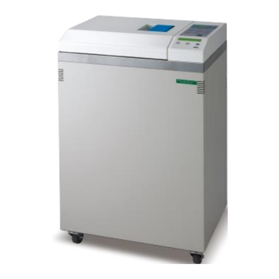
5. Introduction 5.1 Intended Use This product is a vertical high pressure steam sterilizer which is designed and developed for the sterilization of wrapped and unwrapped items. It can also perform sterilization of liquid which is not for medical purpose. 5.2 Description of the Sterilizer 5.2.1 External View Door handle... -
Page 13: Internal Configuration
5.2.2 Internal Configuration Water Level Sensor Over temperature controller Heater Exhaust Stopper Figure 8... -
Page 14: Control Panel (Liquid Program)
5.2.3 Control Panel (Liquid Program) Temperature Panel Display the temperature Visual Alarm Indicator Light inside the chamber. Indicates over-temperature or Display “REC” with recorder type (optional). over-pressure in the chamber. Process Status Indicator Individual LED light to Low Water Indicator Light SA-300VMA-R indicate the current status SA-300VMA... -
Page 15: Control Panel (Re-Dry Program)
5.2.4 Control Panel (Re-Dry Program) Temperature Panel Display the temperature Visual Alarm Indicator Light inside the chamber. Indicates over-temperature or Display “REC” with recorder type (optional). over-pressure in the chamber. Process Status Indicator SA-300VMA SA-300VMA-R SA-300MA Individual LED light to Low Water Indicator Light indicate the current status Indicates the water level is... -
Page 16: Operation
6. Operation 6.1 Operation Overview 6.1.1 Re-Dry Program Put the sterilization items and close door Standard Sterilization Program Select Sterilization Temp.121°C or 134°C Select Re-Dry Button Select Sterilization Item Select Dry Time 0/15/30/35/40 min. Press “START” Button Vacuum, Add Water and Heat Re-Dry (10 min.) Repeat Vacuum and Heat steps for 4 times, and then... -
Page 17: Liquid Program
6.1.2 Liquid Program Put the sterilization items and close door Standard Sterilization Program Select Sterilization Temp.121°C or 134°C Select Liquid Program Select Sterilization Item Button Select Dry/No Dry 0/15/30/35/40 min. Press “START” Button Vacuum, Add Water and Heat Liquid Program Heat to Sterilization Repeat Vacuum and Heat steps for 4 times, and then Heat to Selected Sterilization Temperature. -
Page 18: Pump Test / Bd Test / Prion
6.1.3 PUMP test / BD test / PRION Put the sterilization items and close door B.D. test, PRION Pump Test Press “START” Button Vacuum, Add Water and Heat Vacuum (10 min.) Repeat Vacuum and Heat steps for 4 times, and then Heat to Selected Sterilization Temperature. -
Page 19: Prepare Sterilization
6.2 Prepare Sterilization Follow “4. Installation” to finish installation first. Follow “4.2 Install the sterilizer” to make sure the water inside reservoir is sufficient. C. Check the Pressure Gauge is reading ZERO, and then open the door by turning the door knob 90°... - Page 20 Figure 10...
-
Page 21: Standard Sterilization Program
6.3 Standard Sterilization Program Before start Sterilization program please refer to “6.2 Prepare Sterilization” section. How to set the Standard Sterilization program 121°C or 134°C 120°C 103°C 0 bar (Room Temp.)°C (kgf/cm Vacuum Figure 11 C. Press “STERI TEMP” to select 121°C or 134°C D. -
Page 22: Re-Dry Program (Exclusive Either To Liquid Functions)
On completion, the buzzer will sound same time the display will flash. The program has finished when the buzzer STOPS and the COMPLETE indicator light is illuminated on the Process Status Indicator. WARNING: If the COMPLETE indicator light was not lit, the cycle has failed and should be run again. -
Page 23: Liquid Program (Optional, Exclusive Either To Re-Dry Function)
6.5 Liquid Program (optional, exclusive either to Re-Dry function) Before start Sterilization program please refer to “6.2 Prepare Sterilization” section. How to set the Liquid program 121°C 0 bar (Room Temp.)°C (kgf/cm Figure 14 CAUTION: After the sterilization step finished, the unit will take to exhaust spontaneously. Then the COMPLETE indicator light is illuminated on the Process Status Indicator. - Page 24 On completion, the buzzer will sound same time the display will flash. The program has finished when the buzzer STOPS and the COMPLETE indicator light is illuminated on the Process Status Indicator. WARNING: If the COMPLETE indicator light was not lit, the cycle has failed and should be run again.
-
Page 25: Prion Program
6.6 PRION Program Before start Sterilization program please refer to “6.2 Prepare Sterilization” section. How to set the PRION program 134°C 120°C 103 °C 0 bar (Room Temp.)°C (kgf/cm Vacuum Figure 16 to start “PRION Program”. The corresponding sterilization time will be: C. -
Page 26: Test Program
Open the door and take out the sterilized items. WARNING: Check the Pressure Gauge is reading ZERO before opening the door. WARNING: Beware of steam when opening door after a sterilization cycle. WARNING: Be careful when removing the sterilized items as the metal surfaces might still be hot. - Page 27 NOTE: The DRY step won’t be performed. Figure 19 On completion, the buzzer will sound same time the display will flash. The program has finished when the buzzer STOPS and the COMPLETE indicator light is illuminated on the Process Status Indicator. WARNING: If the COMPLETE indicator light was not lit, the cycle has failed and should be run again.
-
Page 28: Pump Test Program
6.8 PUMP TEST Program Before start Sterilization program please refer to “6.2 Prepare Sterilization” section. How to set the PUMP TEST program 0 kgf/cm (0 bar) Vacuum Figure 20 to start “PUMP TEST Program”. The corresponding sterilization time will be: C. -
Page 29: Vacuum Release
Press the Vacuum/Pressure Release Button to release the chamber pressure. WARNING: Check the Pressure Gauge is reading ZERO before opening the door. 6.9 Vacuum Release Press the Vacuum/Pressure Release Button to release the chamber pressure. The message “OP” will be displayed to notify operation. Please check the Pressure Gauge is reading ZERO before opening the door 6.10 Reset / Stop Press the RESET/STOP Button... -
Page 30: Sterilization For Implements
WARNING: To sterilize absorbent cotton or woolen, please wrap it with sterilizing pouch to avoid piping clog. 6.12.1 Sterilization for Implements Place implements on the tray evenly according to Figure 22, Figure 23. Do not pile up nor overlap each implement. Figure 22 Figure 23 6.12.2 Glassware... - Page 31 Loose lid 2/3 full Figure 24...
-
Page 32: Recorder
7. Recorder 7.1 Intended use This paperless Recorder records the sterilization temperature, theoretical steam pressure and real time information during each cycle as an optional method of printer. It records the specified information onto an USB flash drive, in the Excel csv (Comma Separated Values) format which compatible with Microsoft®... -
Page 33: Description Of Detail Content
7.2.1 Description of Detail Content Printer output Description Model number MODEL:SA-300VMA-R Software version installed in this autoclave Version:V0.99 Series number SN:161005204-001 Program selected Program: 134 Unwrapped Sterilization temperature Ster. Temp:134 ºC Sterilization duration Ster. Time: 4 m Dry duration Dry Time: 15 m Date and Time of sterilization Date:2020/03/13 Time:10:45:57 AM... -
Page 34: Description Of Summary Contents
058:31 111.3 0.07 059:32 111.2 0.08 The maximum and minimum temperature Ster. Temp : 134.7 ~ 136.2 ºC detected during sterilization period The maximum and minimum pressure Ster. Pres : 2.12 ~ 2.22 bar detected during sterilization period Sterilization period Ster. - Page 35 040:20 136.6 2.14 every 1 minutes after “S00”; and also the last 043:22 98.2 0.08 058:31 111.3 0.07 sterilization time 059:32 111.2 0.08 exhaust of water and steam dry time-started dry time-finished end of recording The maximum and minimum temperature Ster.
-
Page 36: Storage Medium
7.3 Storage medium Use only recommended storage medium by the manufacturer such as USB (2.0) flash drive. You should format your storage medium prior insert into the Recorder for the first time. You can operate on the files in this card in PC via a card reader. Data will be stored under the root directory only. -
Page 37: Recorder Panel
7.4 Recorder panel ▲Increase button 1) to move cursor backward LCD: 2) to advance digits 1)Display date and time 2)Display chamber temperature 3)Recording status SET button: ▼ Decrease button 1)to set the parameter 1) to move cursor 2)to confirm adjustment forward 2) to decrease digits USB port... -
Page 38: General
7.5.1 General There are 3 types of operation modes for the recorder, they are stand-by mode, recording mode, and adjusting mode. 7.5.1.1 Stand-by mode The date and time will be displayed after turn on the main power, and low battery symbol will flash for charging and/or low battery as shown in Figure 27. -
Page 39: Adjusting Mode
b) After completing a sterilization cycle, the data will be stored to USB flash drive; and the recorder returns to stand-by mode. The sequences of storage message are shown in the Figure 29. Please Wait! Data transfer 2019- Apr-24 Data transfer… Completed 13:30:30 Figure 29... -
Page 40: Set Up
7.5.2 Set up 7.5.2.1 Set up date and time Press “SET” button for adjusting the parameters of the recorder while in the stand-by mode. Press increase (▲) or decrease (▼) until “1. Date / Time” displayed as shown in Figure 31. 1. -
Page 41: Remove Usb
The sequence is in the order of Temperature - Pressure each time you press the “Set” button. After entering the unit, press “Set” button returns to the Set manual, and then to choose “8. EXIT” press “Set” button again returns to the stand-by mode as shown in Figure 32. 7.5.2.3 Remove USB CAUTION: The data may be damaged if not follow this operation to detach the USB flash drive properly. -
Page 42: Download
7.5.2.4 Download WARNING: The recorder can operate without a USB flash drive, but the data stored in the recorder will be overwritten by the next sterilization data if the recorder memory is full. Manufacturers strongly recommend that you use a USB flash drive as a storage medium and always back up the USB flash drive to a secure area. -
Page 43: Printer
7.5.2.5 Printer Press “SET” button in the stand-by mode and then press increase (▲) or decrease (▼) until “5. Printer” displayed as shown in Figure 40. 5. Printer Figure 40 Press the Setup button to select the printer contents, then press the (▲) and/or (▼) buttons to select as shown in Figure 41. -
Page 44: Exit
7.5.2.8 Exit Press “SET” button in the stand-by mode and then press increase (▲) or decrease (▼) until the “8. Exit” displayed as shown in Figure 44. 8. Exit Figure 44 Press “SET” button returns to the stand-by mode. -
Page 45: Message And Troubleshooting (For Recorder)
7.6 Message and troubleshooting (for recorder) Symptom Solution No display - Turn on the main switch. - Plug the power cable. - Check if bad connection. - Contact local distributor for service E101: Temp. Sensor fail - Contact local distributor for service E103: Pressure sensor - Contact local distributor for service fail... -
Page 46: Test Instructions
8. Test Instructions 8.1 Biological performance of sterilizers It is commonly used as a challenge organism for sterilization validation studies and periodic check of sterilization cycles. The biological indicator contains spores of the organism on filter paper inside a vial. After sterilizing, the cap is closed, an ampoule of growth medium inside of the vial is crushed and the whole vial is incubated. -
Page 47: Air Removal (Bowie-Dick Type Test Pack)
8.2 Air removal (Bowie-Dick type test pack) A commercially available Bowie-Dick type test pack that is of a size appropriate to the chamber being tested. The indicator is a heat sensitive sheet that is placed in the middle of a packet made up of various layers of paper and foam rubber. - Page 48 4. After processing, wear heat-resistant glover to remove the Cube from the sterilizer and allow to cool. WARNING: The metal clamp is hot at this stage of test. 5. Unlock the swing-bar and remove the indicator sheet from the center of the Cube. 6.
-
Page 49: Helix Test
8.3 Helix test The Helix test represents a hollow A-type load, i.e. the load with the most critical characteristics. Carry out the test as follows (Example of TST LOADCHEK STEAM): WARNING: TST LOADCHEK STEAM is trademark of ALBERT BROWNE LTD., 1. - Page 50 WARNING: The HELIX Test kit will be very hot! 6. Open the capsule and remove the test strip. 7. Please ask your dealer of HELIX test. 8. The result is as follows: Incorrect result: Figure 48 Incorrect result: Figure 49 correct result: Figure 50...
-
Page 51: Maintenance Instructions
9. Maintenance Instructions WARNING: Failure to follow the Maintenance Instructions will adversely affect performance and lifespan of the sterilizer, and may invalidate the warranty. WARNING: Before conducting maintenance, please turn off the sterilizer and disconnect from the power supply. Check the sterilizer has cooled down to room temperature. - Page 52 CAUTION: Place a towel underneath the filter tap to avoid leakage. Counterclockwise Filter Nut Towel Figure 51 Take out the filter following the direction of the arrow. Figure 52 Take out the filter carefully, and flush it with water to clean it. Assemble it back as shown in Figure 53.
- Page 53 Figure 53 Install the filter following the direction of the arrow. Lock the filter nut clockwise.
-
Page 54: Monthly
9.3 Monthly Use the non-corrosive cleaner and stiff bristled brush or sponge to clean the water level sensor at the bottom of the chamber as Figure 54. Clean the dirt off at filter of the bottom of the chamber as Figure 54. CAUTION: Clean the dirt off from the sides of the sensor is more important than the tip. -
Page 55: Annually
9.4 Annually CAUTION: An annual maintenance service by a trained engineer is necessary. Contact your distributor for details. The following maintenance instructions are for your reference only. Calibrate the temperature during sterilization process. (Use biological indicators to test the validity of sterilization) Check if there’s any leakage of the piping. -
Page 56: Silicone Door Gasket
9.4.1 Silicone door gasket How to replace the silicone door gasket: 1. Remove the gasket assembly from the door groove, and then take out the door gasket frame, door gasket plate from the old gasket. Install the door gasket frame, door gasket plate to the new gasket as shown in Figure 55. - Page 57 Door Groove Refer to Figure 58 for details Door Figure 57 Door Gasket Frame Door Gasket Plate Silicone Door Gasket Thick end of Silicone Door Gasket Figure 58 CAUTION: Assembly direction - toward the thick end of the Door Groove. CAUTION: The old gasket should be disposed in accordance with the local laws.
-
Page 58: Troubleshooting
10. Troubleshooting 10.1 Symptoms Problem Possible Cause Solution The main cable is Plug in the sterilizer and turn on the socket unplugged or the switch. socket switch is off. Power Forget to turn on the indicator isn’t Press the Power switch to ON ”I” position. switch. -
Page 59: List Of Error Codes
10.2 List of Error Codes ERROR Description CODE K-type sensor in chamber is out of connection (Emergency light illuminates) The door is not closed completely (Door light illuminates) Sterilization temperature over than 137°C (Emergency light illuminates) The water tank is in LOW WATER condition (LOW-WATER light illuminates) Water in the chamber is not enough in first 5 min. -
Page 60: Specifications
11. Specifications Model SA-300VMA-R Chamber Capacity (L) Maximum Instrument Length (mm) Maximum Load (unpouched) (g) 9,000 Maximum Load (pouched) (g) 1,600 External Dimensions (mm) 450 (D) x 600 (W) x 980 (H) Chamber Size (mm) 300 Diameter x 710 Depth Gross Weight (kg) Voltage/Frequency/Wattage 220V-240V AC, 50/60Hz, 2900W... - Page 61 Model SA-300VMA-R Pressure Display Analog pressure gauge Function Display Recorder Memory Recorder, up to 32 G USB (2.0) flash drive Wrapped (121°C 126 min/ 134°C 121 min), Unwrapped (121°C 91 min/ 134°C 90 min), PRION (125 min), B.D. Test (84 min), Pump Test (16 min), Program Liquid (137-182 min), Flash...
-
Page 62: Warranty
12. Warranty WARRANTY "STURDY" product has one (1) year warranty from the date of purchase that covers any defects in materials and quality under regular use. This warranty does not apply to any product damaged by accident‚ misuse, abuse‚ neglect‚ improper line voltage‚... - Page 63 Name Sturdy Autoclave Sterilizer Model SA-300VMA-R Manufacturer Sturdy Industrial Co. Ltd. Address 168, Sec. 1, Zhongxing Rd., Wugu District, New Taipei City, 24872, Taiwan EC Representative APEX MEDICAL S.L. Elcano 9, 6 ª planta 48008 Bilbao. Vizcaya SPAIN 422-03070-01...
Need help?
Do you have a question about the Sturdy SA-300VMA-R and is the answer not in the manual?
Questions and answers