
Subscribe to Our Youtube Channel
Related Manuals for Ambient miniVES

Summary of Contents for Ambient miniVES
- Page 1 Compact Voice Alarm System User Manual EN 54-16:2008 EN 54-4:1997 + AC:1999 + A1:2002 + A2:2006 ver. 11.2021 www.ambientsystem.eu...
-
Page 2: Table Of Contents
LED colors on the control unit front panel _________________________________________ 3. miniVES and midiVES connector panel ________________________________________________ miniVES L series and midiVES 8003R connector panel _____________________________ miniVES LN, midiVES 8003 LN and 8003 LNR series connector panel _______________ 4. miniVES Charger ______________________________________________________________________ miniVES Charger ________________________________________________________________... -
Page 3: Safety
1. Safety Danger! High risk: This symbol indicates an imminently hazardous situation such as "Dangerous Voltage" inside the product. If not avoided, this will result in an electrical shock, serious bodily injury, or death. Warning! Medium risk: Indicates a potentially hazardous situation. If not avoided, this could result in minor or moderate bodily injury. Caution! Low risk: Indicates a potentially hazardous situation. - Page 4 Compact Voice Alarm System User Manual Do not install near any heat sources such as radiators, heat registers, stoves, or other apparatus (including amplifiers) that produce heat or in direct sunlight. No naked flame sources, such as lighted candles, should be placed on the apparatus. Do not defeat the safety purpose of the polarized or ground-type plug.
- Page 5 Do not disassemble the device or attempt to repair or modify it. The device does not include user replaceable components inside the chassis. Opening the chassis and unautho- rized repairs will void the warranty. Unauthorized substitutions may result in fire, electric shock or other hazards.
- Page 6 Compact Voice Alarm System User Manual This label may appear on the bottom of the apparatus due to space limitations. Caution! To reduce the risk of electrical shock, DO NOT open covers. Refer servicing to qualified service personnel only. Warning! To prevent fire or shock hazard, do not expose units to rain or moisture.
-
Page 7: Minives And Midives Front Panel
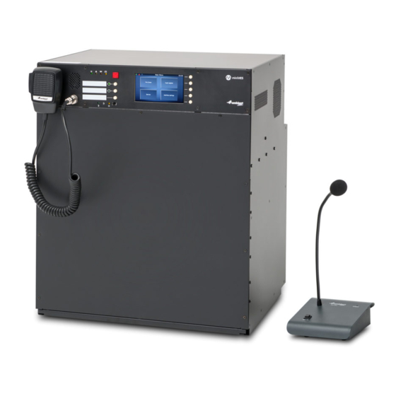
2. miniVES and midiVES front panel Front panel of miniVES Fig. 1. Front panel of miniVES 2001L, 4001L, 4002L, 2001LN, 4001LN, 4002LN series and midiVES 8003LN and 8003LNR Handheld fireman’s microphone Built in speaker Indicators Power supply indicator (green LED) b. -
Page 8: Midives Front Panel
Compact Voice Alarm System User Manual Front panel of midiVES 8003R Fig. 2. Front panel of midiVES 8003R Indicators Power supply indicator (green LED) b. Failure indicator (yellow LED) Emergency indicator (red LED) d. Battery power indicator (yellow LED) Emergency button Configurable function buttons Function button activation LEDs Handheld microphone LED... -
Page 9: Led Colors On The Control Unit Front Panel
LED colors on the control unit front panel Graphic miniVES, midiVES Color symbol Control Units green POWER yellow FAILURE Blocking function active ALARM yellow Battery failure green Handheld microphone active CPU-off yellow function active (CPU bypass) -
Page 10: Minives And Midives Connector Panel
LINE A HV AUDIO IN LINE B LINE A HV AUDIO IN 4002 units 150 mA 350 mA Fig. 3. Line control card arrangement for miniVES systems Control Card slots Charger slots BUS1 BUS2 OUT1 OUT2 OUT3 LINE D LINE C... - Page 11 ABT-xCtrLine-4 control card Local audio bus outputs for 4 line control card operation Logic inputs connector Logic outputs connector Audio I/O connector Auxillary power outputs Temperature sensor input jack Main battery connector Two ABT-xCtrLine-4 control cards Four ABT-xCtrLine-2 control cards Four ABT-xCtrLine-44 control cards...
-
Page 12: Minives L Series And Midives 8003R Connector Panel
150 mA 350 mA Fig. 5. Diagram of the connector panel for miniVES series 2001L, 4001L, 4002L and midiVES 8003R Local audio bus outputs for 4 line control card operation Audio input and output (Audio out not available in midiVES 8003R) -
Page 13: Minives Ln, Midives 8003 Ln And 8003 Lnr Series Connector Panel
LN, midiVES 8003 LN and 8003 LNR series connector panel miniVES LN series as well as midiVES 8003LN / LNR are equipped with extended xNET_mini 1GB/ WAN/RS network card. Extended interface provides additional POE port, 2 logical inputs/ outputs and 2 optional SFP ports for fibre or copper redundant connection. -
Page 14: Minives Charger
350 mA Fig. 7. Connection between VRLA batteries, temp. sensor and miniVES Charger module NOTE: It is crucial to connect the batteries to the system before startup. Once the power supply has been provided, connect loudspeaker lines, logic inputs and outputs, network devices. - Page 15 Connecting midiVES 8003LNR with 8003R: For connecting midiVES 8003LNR with 8003R we can use a single set of 4x12V (VRLA) batteries which is shared between 8003LNR and 8003R. Please remember to set the capacity of the batteries on unit 8003LNR only and select no batteries option in 8003R when using the same bateries.
-
Page 16: Batteries
NOTE: Battery bank has to be connected before connecting main power supply. In case of disconnecting batteries and lack of AC power please wait 60 seconds for fully discharge of miniVES before the battery pack will be reconnected to the system. Improper connection procedure may lead to charger module damage. -
Page 17: Instructions For Performing Basic Functions
Alarm mode Activating alarm mode Lift red button flap (alarm button “activate Evacuation”) and press it. However miniVES system is not equipped with the red button protected by the flap. That means that pressing once the red button on the front panel of miniVES activates the 5 seconds procedure (Evacuation button starts blinking RED) during which the system waits for second press of the button. -
Page 18: Failure Mode
A flashing yellow FAILURE LED means that one of VAS central unit elements or a loudspeaker line is damaged. On miniVES devices and ABT-DFMS the system failure will be indicated by an acoustic signal. When the damage is signaled, press “confirm failure” button to mute the alarm sound, and the system will register that the failure was confirmed by the Operator (this event will be recorded in the event log). -
Page 19: Technical Data
6. Technical data miniVES 2001/4001/4002 L/N, 4002LNR miniVES miniVES Model 2001LN, 4001LN, 2001L, 4001L, 4002L 4002LN, 4002LNR Power supply 230 V AC, IEC C14 3pin terminal Power consumption Up to 600 W (depending on configuration) Number of control slots SD HC cards with capacities up to 32 GB supported Message storage The included 512 MB SLC SDHC card provides more... - Page 20 Compact Voice Alarm System User Manual Harmonic distortion ≤ 0,05% (THD+IMD) Headroom 10 dB ≥ 90 dB Channel separation ≥ 80 dB Output impedance 600 Ω Nominal output level 1 Vrms Standard communication: Communication over large distances: Ű 1000BASE-TX/RJ45 CAT5E cables –...
- Page 21 Case material and finish Steel with powdercoat finish 439 (W) × 176 (H) × 354 (D) mm for 4002LNR Dimensions 440 (W) x 525 (H) x 350 (D) mm for 2001/4001/4002 L/LN Mount options 4 × 10 mm wall mount holes in the back of the case Weight 2001 26 kg Weight 4001...
-
Page 22: Midives 8003R
Compact Voice Alarm System User Manual midiVES 8003R Model midiVES 8003R Power supply 230 V AC, IEC C14 3pin terminal Power consumption Up to 1600 W (depending on configuration) Number of control slots SD HC cards with capacities up to 32 GB supported Message storage The included 512 MB SLC SDHC card provides more than 20 min of message time... - Page 23 Total Harmonic Distortion + Noise < 0,1% (THD+N) Signal to Noise Ratio > 76dB (SNR) Standard communication: Ű 1000BASE-TX/RJ45 CAT5E cables – 2 ports available on the Data communication connector panel Ű 100BASE-TX/RJ45 CAT5 cables – 1 port available on the connector panel, for connections with an external network Communication with PC software: RJ45, twisted pair connection TIA/EIA568-B via Ethernet...
-
Page 24: Midives 8003Lnr , 8003Ln
Compact Voice Alarm System User Manual midiVES 8003LNR , 8003LN Model midiVES 8003LNR midiVES 8003LN Power supply 230 V AC, IEC C14 3pin terminal Power consumption Up to 1600 W (depending on configuration) Number of control slots SD HC cards with capacities up to 32 GB supported Message storage The included 512 MB SLC SDHC card provides more than 20 min of message time... - Page 25 Maximum input voltage ≤ 3 Vrms Rated output voltage 100Vrms / 20 Ω, THD+N < 1% Total Harmonic Distortion + < 0,1% Noise (THD+N) Signal to Noise Ratio (SNR) > 76dB 2 × SFP module 1 Gb/s, 1 × POE 1 Gb/s, 100 Mb/s, 1 × LAN 1 Data communication Gb/s, 100 Mb/s connection;...
-
Page 26: Mounting Instructions
Compact Voice Alarm System User Manual 7. Mounting instructions STEP 1 Remove 4 × M4 TORX screws from part A and take off the front panel. STEP 2 Remove 5 × M3 screws from part B. - Page 27 STEP 3 Remove Locking screws C and pull the drawer towards you D. STEP 4 Drawer release lever. To release, push down on lever on left hand side and pull up on lever on the right hand side. With levers depressed, pull drawer towards you to remove it completely...
- Page 28 Compact Voice Alarm System User Manual STEP 5 Fix the empty chassis to the wall with four screws. Use screws and anchors suiting your type of wall (not provided). Due to the mass of the product (up to 80 kg with the batteries), it is important that the wall-mounted system is safely installed in accordance with local building regulations.
- Page 29 STEP 6 Add the batteries to the dedicated compartment. Check that the battery compartment holds the type of battery selected by the installer. A = 220 mm B = 340 mm C = 430 mm STEP 7 Slide the drawer back in position and tighten the screws.
-
Page 30: Notes
Compact Voice Alarm System User Manual 8. Notes... - Page 32 Ambient System Sp. z o.o. | ul. Bysewska 27 | 80-298 Gdańsk | Poland 1438-CPR-0527 EN 54-16: 2008 EN 54-4:1997 | EN 54-4:1997/AC:1999 | EN 54-4:1997/A1:2002 | EN 54-4:1997/A2:2006 Voice alarm control and indicating equipment with integrated power supply equipment...
Need help?
Do you have a question about the miniVES and is the answer not in the manual?
Questions and answers