
Subscribe to Our Youtube Channel
Related Manuals for Ambient miniVES 2001L

Summary of Contents for Ambient miniVES 2001L
- Page 1 Compact Voice Alarm System User Manual EN 54-16:2008 EN 54-4:1997 + AC:1999 + A1:2002 + A2:2006 ver. 04.2020 www.ambientsystem.eu...
-
Page 2: Table Of Contents
4. miniVES Charger ______________________________________________________________________ miniVES Charger ________________________________________________________________ Batteries _______________________________________________________________________ 5. Instructions for performing basic functions ___________________________________________ Alarm mode ____________________________________________________________________ Failure mode ___________________________________________________________________ 6. Technical data _________________________________________________________________________ miniVES 2001L, 4001L, 4002L ____________________________________________________ miniVES 2001LN, 4001LN, 4002LN ________________________________________________ 7. Mounting instructions ________________________________________________________________... -
Page 3: Safety
1. Safety Danger! High risk: This symbol indicates an imminently hazardous situation such as "Dangerous Voltage" inside the product. If not avoided, this will result in an electrical shock, serious bodily injury, or death. Warning! Medium risk: Indicates a potentially hazardous situation. If not avoided, this could result in minor or moderate bodily injury. Caution! Low risk: Indicates a potentially hazardous situation. - Page 4 Compact Voice Alarm System User Manual Do not install near any heat sources such as radiators, heat registers, stoves, or other apparatus (including amplifiers) that produce heat or in direct sunlight. No naked flame sources, such as lighted candles, should be placed on the apparatus. Do not defeat the safety purpose of the polarized or ground-type plug.
- Page 5 Do not disassemble the device or attempt to repair or modify it. The device does not include user replaceable components inside the chassis. Opening the chassis and unautho- rized repairs will void the warranty. Unauthorized substitutions may result in fire, electric shock or other hazards.
- Page 6 Compact Voice Alarm System User Manual This label may appear on the bottom of the apparatus due to space limitations. Caution! To reduce the risk of electrical shock, DO NOT open covers. Refer servicing to qualified service personnel only. Warning! To prevent fire or shock hazard, do not expose units to rain or moisture.
-
Page 7: Minives Front Panel
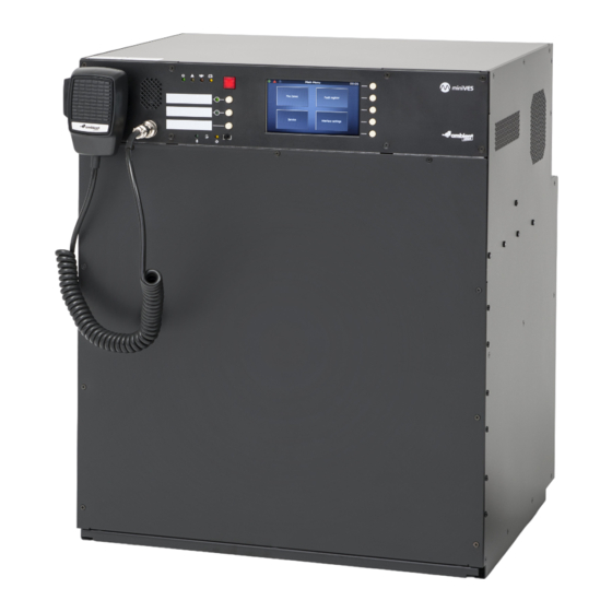
2. miniVES front panel Front panel Fig. 1. Front panel of miniVES 2001L, 4001L, 4002L and 2001LN, 4001LN, 4002LN series Handheld fireman’s microphone Built in speaker Indicators Power supply indicator (green LED) b. Failure indicator (yellow LED) Emergency indicator (red LED) d. -
Page 8: Led Colors On The Control Unit Front Panel
Compact Voice Alarm System User Manual LED colors on the control unit front panel Graphic Color miniVES Control Units symbol green POWER yellow FAILURE ALARM yellow Battery power active green Handheld microphone active CPU-off function yellow active (CPU bypass) -
Page 9: Minives Connector Panel
3. miniVES connector panel Control Card slots Charger slots BUS1 BUS2 OUT1 OUT2 OUT3 TEMP. SENSOR +48 VDC BATT Audio IN Audio OUT +24 VDC +48 VDC LINE D LINE C LINE B LINE A HV AUDIO IN 2001 units 150 mA 350 mA BUS1 BUS2... -
Page 10: Minives L Series Connector Panel
Compact Voice Alarm System User Manual miniVES L series connector panel BUS1 BUS2 OUT1 OUT2 OUT3 LAN/WAN TEMP. SENSOR +48 VDC BATT Audio IN Audio OUT +24 VDC +48 VDC 150 mA 350 mA Fig. 3. Diagram of the connector panel for miniVES series 2001L, 4001L and 4002L units Local audio bus outputs for 4 line control card operation Audio input and output Logic inputs... -
Page 11: Minives Ln Series Connector Panel
miniVES LN series connector panel Units similar to the 2001L, 4001L, 4002L series with the exception of the extended xNET_mini-1GB/ WAN/RS network interface. This provides more connectivity and slots for two optional SFP modules. LAN PoE BUS1 BUS2 OUT1 OUT2 OUT3 LAN/WAN RS485 FIBER... -
Page 12: Minives Charger
Compact Voice Alarm System User Manual 4. miniVES Charger miniVES Charger In order to connect the batteries to the charger use the battery cable supplied with the device. Be sure of proper connection (polarity) between batteries and terminals. Lastly connect the thermis- tor temperature sensor to the “TEMP SENSOR”... -
Page 13: Batteries
Batteries It is necessary to protect batteries from short-circuit while connecting battery leads. Short-circuit may lead to system failure. Follow this manual to assure safety while connecting. Make sure the system power has been switched off before battery is connected. Once the batteries have been connected, make sure all terminals of all batteries have been protected against short-circuit. -
Page 14: Instructions For Performing Basic Functions
Compact Voice Alarm System User Manual 5. Instructions for performing basic functions Alarm mode Activating alarm mode Lift red button flap (alarm button “activate Evacuation”) and press it. However miniVES system is not equipped with the red button protected by the flap. That means that pressing once the red button on the front panel of miniVES activates the 5 seconds procedure (Evacuation button starts blinking RED) during which the system waits for second press of the button. -
Page 15: Failure Mode
Message priorities Activate alarm and select zones. Press “Warning” button – warning message will be played back in given zones. Next, press “Evacuation” button – warning message will stop, and evacuation message will replace it because has a higher priority. Then, press “push to talk” button – all automatic mes- sages will stop and you will be able to transmit a live message via the fireman microphone. -
Page 16: Technical Data
Compact Voice Alarm System User Manual 6. Technical data miniVES 2001L, 4001L, 4002L Model miniVES 2001L, 4001L, 4002L Power supply 230 V AC, IEC C14 3pin terminal Power consumption Up to 600 W (depending on configuration) Number of control slots SD HC cards with capacities up to 32 GB supported Message storage The included 512 MB SLC SDHC card provides more... - Page 17 Headroom 10 dB ≥ 90 dB Channel separation ≥ 80 dB Output impedance 600 Ω Nominal output level 1 Vrms Standard communication: Ű 1000BASE-TX/RJ45 CAT5E cables – 2 ports Data available on the connector panel communication Ű 100BASE-TX/RJ45 CAT5 cables – 1 port available on the connector panel, for connections with an external network PC software: RJ45, twisted pair connection TIA/ Communication with PC...
-
Page 18: Minives 2001Ln, 4001Ln, 4002Ln
Compact Voice Alarm System User Manual miniVES 2001LN, 4001LN, 4002LN Model miniVES 2001LN, 4001LN, 4002LN Power supply 230 V AC, IEC C14 3pin terminal Power consumption Up to 600 W (depending on configuration) Number of control slots SD HC cards with capacities up to 32 GB supported Message storage The included 512 MB SLC SDHC card provides more than 20 min of message time... - Page 19 Channel separation ≥ 80 dB Output impedance 600 Ω Nominal output level 1 Vrms Communication over large distances: Ű 1000BASE X optical fiber Ű 2 ports providing a redundant connection Data Standard communication: communication Ű 1000BASE-TX/RJ45 CAT5E cables – 2 ports available on the connector panel Ű...
-
Page 20: Mounting Instructions
Compact Voice Alarm System User Manual 7. Mounting instructions STEP 1 Remove 4 × M4 TORX screws from part A and take off the front panel. STEP 2 Remove 5 × M3 screws from part B. - Page 21 STEP 3 Remove Locking screws C and pull the drawer towards you D. STEP 4 Drawer release lever. To release, push down on lever on left hand side and pull up on lever on the right hand side. With levers depressed, pull drawer towards you to remove it completely...
- Page 22 Compact Voice Alarm System User Manual STEP 5 Fix the empty chassis to the wall with four screws. Use screws and anchors suiting your type of wall (not provided). Due to the mass of the product (up to 80 kg with the batteries), it is important that the wall-mounted system is safely installed in accordance with local building regulations.
- Page 23 STEP 6 Add the batteries to the dedicated compartment. Check that the battery compartment holds the type of battery selected by the installer. A = 220 mm B = 340 mm C = 430 mm STEP 7 Slide the drawer back in position and tighten the screws.
- Page 24 1438 Ambient System Sp. z o.o. | ul. Galaktyczna 37 | 80-299 Gdańsk | Poland 1438-CPR-0527 EN 54-16: 2008 EN 54-4:1997 | EN 54-4:1997/AC:1999 | EN 54-4:1997/A1:2002 | EN 54-4:1997/A2:2006 Voice alarm control and indicating equipment with integrated power supply equipment...
Need help?
Do you have a question about the miniVES 2001L and is the answer not in the manual?
Questions and answers