Advertisement
Quick Links
Advertisement

Related Manuals for Skriware SkriBot ENIF


Summary of Contents for Skriware SkriBot ENIF
- Page 1 A S S E M B L Y M A N U A L SkriBot MO D EL : EN IF...
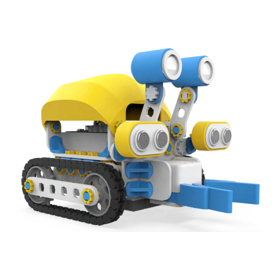
- Page 2 Hello, I’m SkriBot SkriBot Assembly Manual...
- Page 3 Before assembling your SkriBot, Parts list make sure you have all of the parts ready SkriBrain (Microcontroller) Battery pack Battery Charger Range sensor LED eye Gripper Reflectance sensor Motor Passive wheel Drive wheel Shell 1x3 Curved Plate 5x5 Plate 4x5 Plate 2x6 Plate 1x6 Plate 1x5 Plate...
- Page 4 Rotating Bolt Rigid Bolt Passive wheel Drive wheel SkriBot Assembly Manual...
- Page 5 Make sure the nuts are oriented the correct way Wrong Correct How to use tools Tighten the nut only until you feel resistance (about 90º) or you risk breaking it 90º 90º SkriBot Assembly Manual...
- Page 6 CAUTION ! DO NOT OPEN OR CLOSE MANUALLY SkriBot Assembly Manual...
- Page 7 CAUTION ! DO NOT CONNECT THE BATTERY TO SKRIBRAIN BEFORE FULLY ASSEMBLING SKRIBOT SkriBot Assembly Manual...
- Page 8 CHAPTER 1. Robot body construction. We start building SkriBot by constructing its body. What is its body? In case of a human it's a part where arms, head and legs are attached. In case of the SkriBot it is the main part to which we attach other elements such as tracks, sensors and gripper.
- Page 9 Step 1 SkriBot Assembly Manual...
- Page 10 Step 2 Step 1 SkriBot Assembly Manual...
- Page 11 Step 3 Step 2 Step A Step B SkriBot Assembly Manual...
- Page 12 Step 4 Step 3 Step A Step B SkriBot Assembly Manual...
- Page 13 Step 5 Step 4 SkriBot Assembly Manual...
- Page 14 CHAPTER 2. How to make the robot ride? Many vehicles use wheels and the SkriBot is no different. First we start by building a base of blocks, to which we will later attach the wheels. What else is needed? We need two motors to set the wheels in motion.
- Page 15 Step 6 SkriBot Assembly Manual...
- Page 16 Step 7 Step 5 Step 6 Step A Step B SkriBot Assembly Manual...
- Page 17 Step 8 Step 7 SkriBot Assembly Manual...
- Page 18 Step 9 Step 8 Step A Drive Wheel Step B Passive Wheel SkriBot Assembly Manual...
- Page 19 CHAPTER 3. Building the front section of the SkriBot. After the base, we need to build the robot's head. It will allow us to attach sensors thanks to which SkriBot will perform various operations. SkriBot Assembly Manual...
- Page 20 Step 10 SkriBot Assembly Manual...
- Page 21 Step 11 SkriBot Assembly Manual...
- Page 22 Step 12 Step 10 Step 11 SkriBot Assembly Manual...
- Page 23 Step 13 Step 9 Step 12 SkriBot Assembly Manual...
-
Page 24: Connecting The Sensors
CHAPTER 4. Connecting the sensors. When the robot's head is ready we can finally attach lights and sensors! In SkriBot, we use LEDs, small lights that will make its eyes flash in any color. Thanks to the range sensor SkriBot will be able to detect objects on its way and assess their proximity. - Page 25 Step 14 SkriBot Assembly Manual...
- Page 26 Step 15 Step 13 Step 14 Step A Step B SkriBot Assembly Manual...
- Page 27 Step 16 Step 15 Step A Step B SkriBot Assembly Manual...
- Page 28 CHAPTER 5. And what will we find under the SkriBot? And what can we find under the SkriBot? Just like a car, our robot needs a chassis. Why? It will form the basis for the robot's last sensor, the reflectance sensor, allowing SkriBot to move along the route we program for it.
- Page 29 Step 17 SkriBot Assembly Manual...
- Page 30 Step 18 Step 16 Step 17 Remember to route the wires from the sensors to the top - it will make it easier for you to connect them later. SkriBot Assembly Manual...
-
Page 31: Gripper Installation
CHAPTER 6. Gripper installation. The robot's gripper has a function similar to human hands. We can use it to grab an object, lift it up or lower it down. When you finish playing with SkriBot and put it back in the box, remember to keep the gripper folded and raised. - Page 32 Step 19 Step 18 Step A Step B Make sure the notch is facing up Click Start from this side SkriBot Assembly Manual...
- Page 33 CHAPTER 7. Yellow shell installation. SkriBot is almost ready. Time to attach its shell! The shell of the robot - like the shells of insects or turtles, protects what is hidden inside. There are a lot of electronics inside the SkriBot, which should be kept safe. Always keep the shell closed, unless you have a good reason to look inside.
- Page 34 Step 20 Step 19 Step A Step B SkriBot Assembly Manual...
- Page 35 CHAPTER 8. Tracks & battery installation. Time to assemble and mount the tracks. Perhaps they remind you of something? For example, look familiar to those used in tanks? They work the same way. They spread the weight of a vehicle over a large area and improve its grip on the ground.
- Page 36 Step 21 x 36 Click Each track consists of 36 track links SkriBot Assembly Manual...
- Page 37 Step 22 Step 20 Step 21 Click Click Step A Step B SkriBot Assembly Manual...
- Page 38 Step 23 Step 22 Top view SkriBot Assembly Manual...
- Page 39 CHAPTER 9. Connecting the microcontroller. Finally, and most importantly, we connect the the brain of our robot! This is, of course, the microcontroller, which therefore has a function very similar to the human brain. That is why we call it SkriBrain. This is where all the information is stored and all the signals and programs are processed SkriBot Assembly Manual...
- Page 40 Step 24 Step 23 To attach the SkriBrain you need to press it from the top into the Battery pack's tabs (marked in the picture) in order to lock the position. Make sure that all four corners are latched. Click SkriBot Assembly Manual...
- Page 41 CHAPTER 10. Connecting sensors to the microcontroller. Do not detach SkriBrain from its mounting plate. Turn the power off before removing and plugging any cables! SkriBot Assembly Manual...
-
Page 42: Programmable Leds
CONNECTING SENSORS Programmable LEDs LED1 LED2 LED1 LED2 Top view SkriBot Assembly Manual... - Page 43 CONNECTING SENSORS Reflectance sensors Top view SkriBot Assembly Manual...
- Page 44 CONNECTING SENSORS Range sensors Top view SkriBot Assembly Manual...
- Page 45 CONNECTING SENSORS Gripper Color coding of the cables is essential for the grabber to work. Please make sure you position the servo connector properly. SERVO1 SERVO2 SERVO1 SERVO2 Top view SkriBot Assembly Manual...
- Page 46 CONNECTING SENSORS Motors MOTOR3 MOTOR2 MOTOR2 MOTOR3 Top view SkriBot Assembly Manual...
- Page 47 CONNECTING ELECTRONICS Battery SkriBot Assembly Manual...
- Page 48 Turning the SkriBot on/off After making sure that everything is connected correctly, turn on the SkriBot with the toggle marked in the picture. Small diode next to the toggle will turn on, indicating that SkriBot has a power supply. SkriBot Assembly Manual...
-
Page 49: Battery Led
Battery LED Battery charged Charge the battery Battery critical! Charge the battery immediately SkriBot Assembly Manual... -
Page 50: Bluetooth Led
Bluetooth LED Skribot paired Skribot unpaired Communication error SkriBot Assembly Manual... - Page 51 Opening the shell Be aware of the cables Press Press Press Press SkriBot Assembly Manual...
- Page 52 Charger Indicator Battery charged Charging battery SkriBot Assembly Manual...
- Page 53 SkriApp SkriApp works with tablets or smartphones with both iOS and Android operating systems. SkriApp allows you to control SkriBot remotely and program it via a user-friendly interface. SkriBot Assembly Manual...
- Page 54 SkriBot Calibration After assembling your SkriBot, you If your SkriBot drives off to should calibrate its motors and contrast the left, move the slider to sensors to work in your environment the right Pair your SkriBot Change the spin direction of the wheels Go to calibration window.
Need help?
Do you have a question about the SkriBot ENIF and is the answer not in the manual?
Questions and answers