
Related Manuals for Vinotemp WINE-MATE WM-1520SSL


Summary of Contents for Vinotemp WINE-MATE WM-1520SSL
- Page 1 Ceiling Split Cooling System Installation, Operation & Care Manual WM-1520SSL WM-2520SSL WM-4520SSL WM-6520SSL www.vinotemp.com - 1 -...
- Page 2 Read and save these instructions Important Safety Information WARNING: • Do not use a ground fault interrupter (GFI). • A dedicated 10 AMP circuit for WM-1520~4520SSL and 15 AMP for WM- 6520SSL are required. WARNING To avoid the risk of electrical shock, property damage, personal injury, or death: •...
-
Page 3: Table Of Contents
Table of Contents Cellar Construction.…………………………….……………..3 Features & Specifications…………………….….…………..4 Temperature & Humidity……….…………..………..……….6 Care Guide……………………………………………………10 User’ Troubleshooting…….………………………………...11 Installer’s Instructions………….…..….……..…………….15 Electrical Wirings..…………….…..….……..………………25 Customer Support……………………………………………28 Warranty……………………………………………………….29 - 3 -... -
Page 4: Cellar Construction
Cellar Construction This is only a guide and shall be considered as minimum requirements. All interior walls and floors shall have a vapor barrier and a minimum of R13 insulation. All exterior walls and ceiling shall have a vapor barrier and a minimum of R19 insulation. -
Page 5: Features & Specifications
Features and Specifications • Wine-Mate ceiling mount split cooling systems WM-1520~6520SSL are designed and used to provide a cold temperature between 50~65 °F for a properly insulated wine cellar. • The wine cellar will maintain humidity range within 50~70% RH. •... - Page 6 NOTE: To prepare rough-in, leave minimum 4” clearances for electrical wiring and refrigeration piping. The specifications and dimensions are listed as follows: Model No Evap Unit Cond Unit Btu/ Cellar Refrigerant Electrical Weight (lb) W”xD”xH”- L”xD”xH” Size Evap Unit/ Evap Unit/ A”xB”...
-
Page 7: Temperature & Humidity
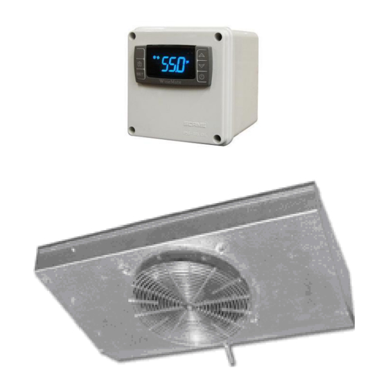
Temperature and Humidity 1. The controller Fig. 2 TEMPERATURE CONTROLLER 1) Keys SET: To display set-point; in programming mode it selects a parameter or confirms an operation. : To start a manual defrost. : To see the maximum stored temperature; in programming mode it browses the parameter codes or increases the displayed value. - Page 8 4) Alarm Signals The alarm codes are described as follows. MESSAGE CAUSE FUNCTION Temperature probe Compressor switching to Con and faulty High temperature Probe temperature ALU higher alarm than the setting temperature; Outputs unchanged Low temperature Probe temperature ALL lower than alarm the setting temperature;...
- Page 9 5. Manual Defrost Press and hold the defrost key until defrost starts. The defrost indicator will be 6. Parameter Programming keys until the “°C” or “°F” LED starts flashing, then 1) Press and hold the SET + release the keys. 2) Press and hold again the SET + keys until the Pr2 label is displayed, then release the keys.
- Page 10 8. How to adjust defrost cycle In case there is excessive frost, the parameters FnC = C-y, idF = 4 and MdF = 20 can be used to avoid frost. 9. How to adjust the humidity The parameter Fon is used to adjust the humidity in the wine cellar. Higher Fon results in higher relative humidity.
-
Page 11: Care Guide
Care Guide In general, always unplug system or disconnect power while doing care. 1. Coil Cleaning • Clean the condenser coil regularly. Coil may need to be cleaned at least every 6 months. • Use a vacuum cleaner with an extended attachment to clean the coil when it is dusty or dirty. -
Page 12: User' Troubleshooting
User’s Troubleshooting This Troubleshooting Chart is not prepared to replace the training required for a professional refrigeration service person, not is it comprehensive. Complaint Possible Causes Response a. Power cord not plugged a. Check power cord 1. Unit not running b. - Page 13 e. Check both evaporator Evaporator or condenser airflow condenser fans Check for air restrictions, air short- g. Dirty Condenser circulation, grille directions h. Iced evaporator g. Clean condenser Refrigeration system restriction h. Defrost and reset temperature Refrigerant leak Call service k.
- Page 14 a. Evaporator air flow restriction a. Check for fans and CFM 14.Evaporator freezing b. Condenser air flow restriction b. Check for fans and CFM c. Not stopping due to air leak, high c. Check for seal, door opening, ambient ambient temperature temperature and temperature setting temperature setting...
-
Page 15: Installer's Instructions
WINE-MATE split system is shipped as components and is ready for use only after a certified refrigeration technician has properly installed the system. Proper installation is critical. Vinotemp can only warrant the quality of the components. The installation and proper operation of the system must be warranted by the installer. - Page 16 Suction line copper tubing CAUTION: Liquid and suction line locations may differ from what are shown here, please check on the units for proper installation. Fig. 3 WM-152~252SFCL Evaporator Unit Fig. 4 WM-452~652SFCL Evaporator Unit - 16 -...
- Page 17 Fig. 5 WM-152~452SCU Condensing Unit Fig. 6 WM-652SCU Condensing Unit - 17 -...
- Page 18 Fig. 7 Liquid Filter Fig. 8 Liquid Indicator Fig. 9 Temperature Controller (4.25”L X 3.75D X 4.25”H) 2. Temperature Controller and Air Probe Installation 1) The temperature controller can be mounted either inside or outside the wine cellar, but the air probe must be located inside the wine cellar. 2) The air probe shall be located in the wine cellar 5 ft above the floor or the air return area, but it shall not be located in the air supply area or other areas where air is not circulated.
- Page 19 4. Condensing Unit Installation CAUTION: Low ambient condition kit is required if the installation area will be below ° If the condensing unit is equipped with a low ambient condition kit, do not turn on the compressor until the condensing unit has been powered for minimum 12 hours.
- Page 20 BACK POSITION FRONT POSITION MIDDLE POSITION Fig. 11 Base Valve Operation Checking Pressure Control Settings Use of the adjustable pressure control (if applicable for pump-down) Suction pressure setting: Cut out=5 psig; Cut in=25 psig; Differential=20 psig Head pressure setting: Cut out=230 psig; Cut in=150 psig; Differential=80 psig It may need to adjust the setting in the field to get the right cycle time.
- Page 21 2) Use of the encapsulated pressure control (if applicable) Fixed suction pressure setting: Cut in = 32 psig; Cut out = 10 psig Fig. 13 Fixed Pressure Control Low ambient condition kit (if applicable) Use of the condenser fan control Head pressure setting: Cut in=170 psig;...
- Page 22 • The line connection sizes of liquid filter & indicator, the valve connection sizes of condensing unit and the line connection sizes of evaporator unit are not necessary the same as the listed refrigeration line sizes. • If the condensing unit is installed above the evaporator unit, use the suction line one listed size smaller.
- Page 23 1) Evacuate the system; both discharge and suction valves must be in the middle positions during evacuating. 2) Charge the system through both suction and discharge valves with refrigerant using the recommended initial amount; both discharge and suction valves must be in the middle positions during charging.
- Page 24 To read properly the service valves must be in the middle positions. Complaint Possible Causes 1) High suction pressure and low head pressure 1) Compressor may be bad Zero superheat and zero subcooling 2) High suction pressure and low head pressure 2) Expansion valve opened, too Low superheat and low subcooling much oil...
- Page 25 Electrical Wiring Diagrams CAUTION: • Hidden lines are the field wirings. • Use minimum 14 gauge wires for power lines. • If equipped with low ambient condition kit, use low ambient temperature wiring diagrams. • A safety switch is always recommended for the condensing unit. Fig.
- Page 26 Fig. 17 WM-6520SSL Electrical Wiring Diagram Fig. 18 Low Ambient Temperature WM-1520~4520SSL-LA Electrical Wiring Diagram - 26 -...
- Page 27 Fig. 19 Low Ambient Temperature WM-6520SSL-LA Electrical Wiring Diagram - 27 -...
-
Page 28: Customer Support
Customer Support If you need further assistance, please contact us at: Vinotemp International 17631 South Susana Road Rancho Dominguez, CA 90221 Tel: (310) 886-3332 Fax: (310) 886-3310 Email: info@vinotemp.com - 28 -... -
Page 29: Warranty
While every effort has been made to provide accurate guidelines, VINOTEMP can not warranty its units to cool a particular enclosure. In case of failure, VINOTEMP cooling units must be repaired by the factory or its authorized agent. Repairs or modifications made by anyone else will void the warranty. - Page 30 VINOTEMP will, at its discretion, repair or replace the unit and return it free of charge to the original retail customer. If the unit is found to be in good working order, or beyond the initial twelve month period, it will be returned freight collect.
Need help?
Do you have a question about the WINE-MATE WM-1520SSL and is the answer not in the manual?
Questions and answers