Table of Contents
Advertisement
Quick Links
Advertisement
Table of Contents

Related Manuals for Aerogen Aeroneb lab AG-AL1000


Summary of Contents for Aerogen Aeroneb lab AG-AL1000
- Page 1 Instruction Manual © 2004 Aerogen, Inc. Part No. AG-AL1010 Rev. C...
-
Page 2: Table Of Contents
Table of Contents Introduction ................3 System description ..............4 Warnings ................5 Cautions ................5 Electromagnetic Susceptibility.......... 5 Symbols ................6 Controls and indicators............. 7 Assembly and installation ............8 Adding Liquid ................ 9 Functional test ..............10 Maintenance................ 11 Troubleshooting.............. -
Page 3: Introduction
9 volts DC. This can enable the timing of aerosolization based on programmed criteria. ® The Aeroneb Lab is a latex-free nebulizer system that incorporates Aerogen’s proprietary OnQ™ Aerosol Generator for aerosolization. ® Note: The Aeroneb Lab, utilizing OnQ™... -
Page 4: System Description
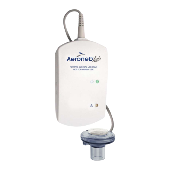
System description ® The Aeroneb Lab (Figure 1) includes the following components: Nebulizer unit (containing the OnQ Aerosol Generator and filler cap), control module, control module cable, AC/DC adapter and DC cable. Filler Cap 1. Nebulizer Unit 2. Control Module (Including Filler Cap) 3. -
Page 5: Warnings
Use only with components specified by Aerogen. Inspect all parts before use, and do not use if any parts are missing, cracked or damaged. In case of missing parts, malfunction or damage, contact your Aerogen representative. Do not use or store outside of specified environmental conditions. -
Page 6: Symbols
Symbols ® The following symbols apply to the Aeroneb Lab and appear on the back of the control module and on the packaging: ® Table 1: Aeroneb Lab System symbols Symbol Meaning Symbol Meaning Serial number, where YY is the year Control Module Output –... -
Page 7: Controls And Indicators
Controls and indicators FOR PRE-CLINICAL USE ONLY NOT FOR HUMAN USE ® Figure 2: Aeroneb Lab controls and indicators ® Table 2: Aeroneb Lab control/indicator functions Control/indicator Function Amber Warning LED When illuminated, indicates nebulizer is disconnected or faulty connection. Green Power/delivery LED When illuminated, indicates that power is supplied and that... -
Page 8: Assembly And Installation
Assembly and installation 1. Clean the nebulizer unit as described in the maintenance section of this manual prior to first use and between uses. 2. Insert the filler cap into the opening on the nebulizer unit. Deleted: Figure 3: Connecting filler cap to nebulizer unit. 3. -
Page 9: Adding Liquid
5. When powering the control module using the AC/DC adapter: • Insert the adapter jack into the control module. • Plug the adapter plug into wall socket mains. Adding Liquid Open the filler cap tab on the nebulizer unit. Use a prefilled ampoule or syringe to add liquid into the filler port of the nebulizer (Figure 5). Close the filler cap tab. -
Page 10: Functional Test
Functional test ® To perform a functional test of the Aeroneb Lab before each use or to verify proper operation, follow these steps: 1. Visually inspect the device for cracks or damage and replace if any defects are visible. 2. Pour 0.5 mL of sterile water or normal saline into the nebulizer unit. 3. -
Page 11: Maintenance
Maintenance ® This section describes how to clean, sterilize, and inspect Aeroneb Lab components. Nebulizer unit (including filler cap). To clean unit between uses for the same subject 1. Disconnect the control module and cable from the nebulizer unit. 2. Remove the filler cap from the nebulizer unit. 3. -
Page 12: Troubleshooting
Troubleshooting ® Table 3: Aeroneb Lab Troubleshooting If this happens: It could mean: Try this: The indicator lights, but No liquid in nebulizer unit. Refill liquid through filler cap in the aerosol is not visible. nebulizer unit (see Adding Liquid). Nebulizer unit has not been properly Clean nebulizer unit (see cleaned. -
Page 13: Specifications
Specifications Physical Nebulizer unit dimensions: 45 mm H x 50 mm W x 50 mm D (1.77 in. H x 1.97 in. W x 1.97 in. D). Control module dimensions: 33 mm H x 75 mm W x 131 mm D (1.3 in. - Page 14 Manufacturer: Aerogen (Ireland) Limited Galway Business Park Dangan Galway Ireland Customer Service Telephone: +353-91-502550 ® Aeroneb Lab Nebulizer System Instruction Manual...
Need help?
Do you have a question about the Aeroneb lab AG-AL1000 and is the answer not in the manual?
Questions and answers