
Related Manuals for ARMTEL DW-IP2


Summary of Contents for ARMTEL DW-IP2
- Page 1 DW-IP2 Weatherproof call station RMLT.465311.006UM1 User Manual Document version 12 26.30.23.000 2022...
- Page 2 © Armtel info@armtel.com...
-
Page 3: Introduction
This User Manual is intended for introducing «DW-IP2 Weatherproof call station» including versions of RMLT.465311.006-100...RMLT.465311.006-207 (Table 1), manufactured by Armtel LLC and is intended to familiarize the User with the device and the procedure for its operation at the installation site. - Page 4 (PA/GA) communication system IPN manufactured by Armtel LLC. Short name of the product – DW-IP2. DW-IP2 can be used in chemical, mining, oil and gas, metal processing and wood processing industries, and other. Maintenance personnel for DW-IP2 shall be appointed by the management at the installation site.
-
Page 5: Eng
DW-IP2 WEATHERPROOF CALL STATION User Manual SAFETY PROVISIONS During installation and operation, observe safety precautions laid out in “Occupational safety rules when operating electrical installations” when working with electrical receivers with voltage of up to 1000 V. In order to ensure fire safety, follow the following rules: −... -
Page 6: Table Of Contents
1.2.5 Pushbuttons (direct call buttons) ......................20 1.2.6 «SOS» and «INFO» modules ........................21 1.2.7 Handset ................................21 1.2.8 Electrical mechanical relay ........................21 1.2.9 CCS-DW-IP2 main board .......................... 22 1.2.10 DART-6UL processor module ....................... 22 1.2.11 DW-BC board .............................. 23 2 INTENDED USE ................................24 2.1 Operating limits .............................. - Page 7 5 STORAGE .................................... 37 6 TRANSPORTATION ................................. 38 7 DISPOSAL ................................... 38 APPENDIX A (reference) External appearance of DW-IP2 versions ..............39 APPENDIX B (reference) PoE function in DW-IP2 ....................42 APPENDIX C (reference) Connection........................... 44 APPENDIX D (reference) Light indication ........................48 armtel.com...
-
Page 8: Description And Operation
SIP server manufactured by Armtel LLC) public address systems in industrial facilities and on transportation. DW-IP2 has a modular design, and depending on the modules installed. The version may vary in accordance with Table 1. The external appearance of all DW-IP2 versions is shown in Appendix А. - Page 9 − control (commutation) of external actuating devices using an integrated electro- mechanical relay (lamp-type signaling device). Configuration of the DW-IP2 shall be carried out using the personal computer of the IPN network administrator on which RU.RMLT.00041-01 IPN Config Tool software is installed.
-
Page 10: Main Spetifications
Maximum electrical power of the amplifier is 25 W*, not less than, W Maximum power of integral relay when external execution units (devices) are connected (in supply voltage range of DW-IP2)*, max, W, Bandwidth of LF signal (-3 dB) of the transmit and receive assembly... - Page 11 DW-IP2 WEATHERPROOF CALL STATION User Manual Table 2 – Main specifications and performance characteristics (continuation) Parameter Value SIP, Armtel-IP, SNMP, Communication protocols SNTP Audio data format (coder/decoder)): - over SIP protocol G.711A (A-Law) G.711U (µ-Law) G.722.1 - over Armtel-IP protocol...
- Page 12 *** Without package and mounting kit. The design and material of the DW-IP2 housing provide protection from external influences. The design and material of the DW-IP2 housing provide impact resistance, have good conductivity, absence of static electricity, and chemical resistance. The material has resistance to ultraviolet radiation, oil and gas resistance, resistance to chemical environment, as indicated in Table 3.
-
Page 13: Operations Conditions
GOST 30804.6.2-2013 (IEC 61000-6-2:2005) with performance criteria not lower than B. Note – Performance criteria when DW-IP2 powered via PoE injector is not lower then A, via terminal block is not lower then B. Under the influence of electrostatic discharges on the product enclosure from 2 kV to 6 kV, when connected to the PoE injector, it is necessary to connect by shielded cable to an earthed PoE injector. -
Page 14: Dw-Ip2 Design
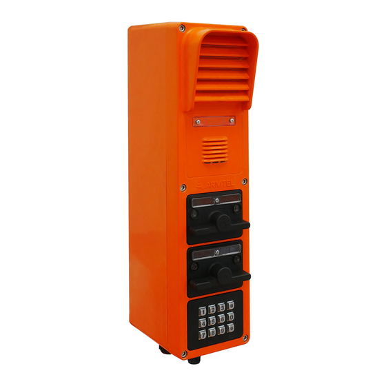
-178…-180, -196…-198 1 – loudspeaker; 2 - marking panel; 3 – microphone; 4 – LEDs for indication DW-IP2 ; 5 – two-way toggle; 6 – nameplate; 7 – plugs; 8 – cable glands for cables 8 - 17 mm dia (2 pcs.);... - Page 15 Depending on DW-IP2 version, one to three modules with two-way toggle (5) or dial pad (14)/pushbuttons (direct call buttons)/buttons/handset with bracket with reed relay (12) can be mounted in the lower part of the cover.
- Page 16 DW-IP2 WEATHERPROOF CALL STATION User Manual 2, 4, 10 – («SW6», «SW5», «SW4») - two-positions DIP-switches for the type of installed modules in the corresponding cover compartments. The correspondence of the switch positions and the installed modules is shown in Table 4, where "x" is the DIP-switch number.
- Page 17 Figure 5) are mounted on the CCS-DW-IP2 main board by М2 threaded bushings. Also, the cooling radiator is installed above the ADSL module through the M2 threaded bushings. The standard 35 mm DIN rail (1) is fasten in the DW-IP2 enclosure by M4 screws through the threaded bushings.
- Page 18 User Manual 1 – DIN rail, 2 – amplifier 25W, 3 – CCS-DW-IP2 main board, 4 – NE01 board, 5 – chassis, 6 – cable glands, 7 – terminal blocks, 8 – cable for DW-BC board connection, 9 – “BTN” button XS1 (CCS-DW-IP2 main board) –...
-
Page 19: Marking
25 W shall be powered from a separate source. Rubber gasket seals under the cover, integrated loudspeaker, and microphone, two- way toggle, as well as in cables glands of DW-IP2 ensure its IP66 ingress protection rating as per GOST 14254-2015 (IEC 60529:2013). -
Page 20: Package
User Manual 1.1.6 Package The DW-IP2 with the assembly kit and documents, which come with the supply package, is packed in consumer package (cardboard box) according to GOST 23088-80. A label in Russian language and English language is glued onto the consumer package, said label containing the following inscriptions and symbols: −... -
Page 21: Description And Operation Of Product Components
User Manual 1.2 Description and operation of product components 1.2.1 General information This subsection describes basic parts of the DW-IP2: − amplifier 25 W (for versions with an amplifier 25 W, listed in Table 1); − integrated amplifier; − ADSL IB02 module (for versions with an ADSL module, listed in Table 1);... -
Page 22: Adsl Module
1.2.3 ADSL module DW-IP2 versions with an ADSL module (refer Table 1) re equipped with an integrated ADSL IB02 module, which is mounted in the enclosure of DW-IP2 parallel for the CCS-DW-IP2 main board. When operating via an ADSL line, the module supports the IEEE802.3i (10BaseT), ITU-T G.992.1…992.5 standards, which provide duplex... -
Page 23: Sos" And "Info" Modules
Modules "SOS", "INFO" are intended for use in emergency situations and have a visual designation of links using a large button with a well-read color inscription above it. Modules can be installed in any of the three plug-in slots in the DW-IP2 cover according to the DW- IP2 design. -
Page 24: Ccs-Dw-Ip2 Main Board
The CCS-DW-IP2 main board receives and processes notification signals and voice messages, amplifies and transfers them to the DW-BC board. Depending on the DW-IP2 version, the following lines are routed from terminal blocks to main board: − Ethernet interface line with РоЕ;... -
Page 25: Dw-Bc Board
User Manual 1.2.11 DW-BC board DW-BC board is installed on the inner side of the DW-IP2 cover and is designed to switch the integrated loudspeaker, microphone, button modules/ two-way toggle and the handset with CCS-DW-IP2 main board. DW-BC board provides signal processing for two-way toggle, pushbuttons or dial pad,... -
Page 26: Intended Use
2.1.1 The product shall be used under exposure factors and ambient parameters which do not exceed permissible values given in 1.1.3. 2.1.2 In is allowed to supply power to DW-IP2 versions with amplifier 25 W (see Table 1) from PoE injector only if the requirement for amplifier 25 W connection to 48 V external power source is complied with. -
Page 27: Preparation For Use
192.168.100.10, subnet mask: 255.255.255.0. Since units with identical IP addresses are not allowed in the same network, it is necessary to set an IP address for each DW-IP2 before connection to the common network. IP address is set from the network administrator PC on which RU.RMLT.00041-01 IPN Config Tool software. -
Page 28: Installation, Connection And Dismantling
User Manual Enter a record on the set IP address in the “Special notes” section of the product passport; Install the cover into its place and fasten it with screws. Install DW-IP2 at the place of operation. 2.4 Installation, connection and dismantling Safety precautions given in 2.1 and 2.2 must be observed during installation,... -
Page 29: Connection
DW-IP2 WEATHERPROOF CALL STATION User Manual Figure 4 – Installation of DW-IP2 2.4.2 Connection ATTENTION! TO PROVIDE IP CLASS, IT IS NECESSARY TO USE CABLES WHICH DIAMETER CORRESPOND TO THE DIAMETERS OF THE CABLE GLANDS. IN CASE USING CONNECTION CABLES WITH A DIAMETER LESS THAN THE DIAMETER OF THE CABLE GLANDS, THE MANUFACTURER DOES NOT GUARANTEE THE PRODUCT COMPLIANCE WITH IP66. -
Page 30: Dismantling
Note – On request, the product can be manufactured with additional cable glands. Enter communication and power cables through the sealing cable glands into the DW-IP2 housing. Strip the cable wires from insulation (connection cables are not supplied with the product). Peeled wire end length for the corresponding sockets is given in Tables C.1 –... - Page 31 DW-IP2 WEATHERPROOF CALL STATION User Manual − disconnect the wires of cables fed into the housing from terminal blocks and sockets on the boards; − loosen the nuts of cable glands and remove the cables. Install the plugs of cable glands and tighten the glands;...
-
Page 32: Operation
Work with the RU.RMLT.00041-01 IPN Config Tool software is carried out from the PC of the IPN system administrator. Note - In addition to using the IPN Config Tool software, the DW-IP2 can be configured using the built-in WEB interface, which can also be used to update the software, download and save the configuration. -
Page 33: Product Operating Modes
− turn on the power supply of DW-IP2 and wait for DW-IP2 to load; − press the “BTN” button (9, Figure 3) on the CCS-DW-IP2 board and hold it for at least 5 s. After the button is released, the configuration file is read with the default settings "default.par", followed by saving the settings to the main... - Page 34 Using DW-IP2 version with the handset, the subscriber can control call receiving and ending, as well as carry communicate in semiduplex mode with subscribers of duplex devices via SIP protocol.
-
Page 35: Procedure For Monitoring The Operability Of The Product
User Manual 2.5.3 Procedure for monitoring the operability of the product The possible states of the DW-IP2 indicators (4, Figure 1), depending on its operating mode, are shown in Table 6. Table 6 – The possible states of the DW-IP2 indicators Indicator Сondition... -
Page 36: Troubleshooting
Handset does not work Handset cable not connected handset cable connection to Х6 socket of DW-BC board * Configuration of DW-IP2 connections and functions is carried out using IPN Config Tool software or a built-in WEB interface page 34/48 armtel.com ©... -
Page 37: Maintenance
− removal of dust and dirt from the surface of the product. Depending on the level of dirt, the surface of the DW-IP2 can be cleaned using a wet sponge soaked with a mild soap solution, or modern chemicals for cleaning and protecting equipment at facilities with corrosive gases and chemical vapors;... -
Page 38: Checking Operability
DW-IP2 WEATHERPROOF CALL STATION User Manual 3.4 Checking operability 3.4.1 Checking the audio path The audio path should be checked via test communication sessions with subscribers, operation with which is programmed during product configuration. Checking is carried out using provisions of section 2.5. If necessary, the volume of the integrated speaker and external loudspeaker, as well as microphone sensitivity are adjusted using software of the IPN system administrator workstation. -
Page 39: Pepair
User Manual 4 PEPAIR No scheduled repair work is provided for DW-IP2. Unscheduled repair shall be performed by the manufacturer at the request of the User. The place, time, procedure and cost of the work shall be agreed with the manufacturer in advance. -
Page 40: Transportation
DW-IP2 WEATHERPROOF CALL STATION User Manual 6 TRANSPORTATION The product shall be transported in in the manufacturer's individual package as a packaging unit by road, river, railway and air transport (expect unsealed compartments), with compliance with the following conditions: − absence of direct ingress of atmospheric precipitation, water splashes, solar UV radiation, dust, sand, aerosols;... -
Page 41: Appendix A (Reference) External Appearance Of Dw-Ip2 Versions
DW-IP2 WEATHERPROOF CALL STATION User Manual APPENDIX A (REFERENCE) EXTERNAL APPEARANCE OF DW-IP2 VERSIONS RMLT.465311.006-100, RMLT.465311.006-101, RMLT.465311.006-102, RMLT.465311.006-103, -118, -136, -154, -172, -190 -119, -137, -155, -173, -191 -120, -138, -156, -174, -192 -121, -139, -157, -175, -193 RMLT.465311.006-104, RMLT.465311.006-105, RMLT.465311.006-106,... - Page 42 DW-IP2 WEATHERPROOF CALL STATION User Manual RMLT.465311.006-108, RMLT.465311.006-109, RMLT.465311.006-110, RMLT.465311.006-111, -128, -146, -164, -182, -200 -129, -147, -165, -183, -201 -126, -144, -162, -180, -198 -127, -145, -163, -181, -199 RMLT.465311.006-112, RMLT.465311.006-113, RMLT.465311.006-114, RMLT.465311.006-115, -130, -148, -166, -184, -202 -131, -149, -167, -185, -203...
- Page 43 DW-IP2 WEATHERPROOF CALL STATION User Manual RMLT.465311.006-116, RMLT.465311.006-117, -134, -152, -170, -188, -206 -135, -153, -171, -189, -207 Figure А.1 – External appearance of DW-IP2 versions armtel.com page 41/48 info@armtel.com © Armtel...
-
Page 44: Appendix B (Reference) Poe Function In Dw-Ip2
Figure B.1 – IEEE 802.3af standard DW-IP2 satisfies requirements of the IEEE 802.3af standard on automatic determination of power rating (it is taken into account, that amplifier 25 W is not supplied from PoE injector). When using a load detection procedure in an active PoE power device (injector), supply voltage in the line will be turned on only after confirmation that the load class matches power supply capabilities. - Page 45 DW-IP2 WEATHERPROOF CALL STATION User Manual DW-IP2 satisfies Class 0 load parameters, the characteristics of this class are given in Table B.1: Table B.1 – Characteristics IEEE 802.3af Class 0 Name Value from 37 to 57 V DC voltage range on powered device...
-
Page 46: Appendix C (Reference) Connection
The DW-IP2 may be connected through various sockets depending on the version of the product. In DW-IP2 versions with amplifier 25 W (see Table 1) the amplifier shall be connected to the external 48 VDC power source via contacts 3 and 4 of the terminal block The location of the connection interfaces is shown in Figure 3. - Page 47 The contact numbering and assignment of the RJ45 type power supply and communication socket XS1 is given in Table C.2. Table C.2 – Contact numbering and assignment of the RJ45 type XS1 socket on the CCS-DW-IP2 main board Function...
- Page 48 XS3 (Table C.1). The contact numbering and assignment of clip connector X1 is given in Table C.3. Table C.3 – Contact numbering and assignment of clip connector X1 on the CCS-DW-IP2 main board Contact External appearance of the X1 clip...
- Page 49 0,205 to 0,518 mm Peeled wire end length: 11 mm To avoid damage during transportation and operation of the DW-IP2, internal wiring cables are securely fixed at special points. Do not use brands of wires for internal wiring that are not provided by the manufacturer.
-
Page 50: Appendix D (Reference) Light Indication
DW-IP2 WEATHERPROOF CALL STATION User Manual APPENDIX D (REFERENCE) LIGHT INDICATION D.1 Light indication of DW-IP2 is given in Table D.1 Light indication of Table D.1 – DW-IP2 Full indication cycle – 1200 ms Next cycle Device operating mode Device in standby mode,... - Page 51 © Armtel...
- Page 52 ARMTEL LLC Tel./fax: +7 (812) 703-41-11 www.armtel.com | info@armtel.com Legal and physical address: Russia, 192012, Saint Petersburg, Zaporozhskaya str., 12 building 1, office 1/2 TECHNICAL SUPPORT 8-800-500-90-17 (for calls from Russian Federation) +7-812-633-04-02 (for international calls) support@armtel.com MORE INFORMATION ABOUT PRODUCT ON OFFICIAL SITE...
Need help?
Do you have a question about the DW-IP2 and is the answer not in the manual?
Questions and answers