Table of Contents

Related Manuals for Trox Technik EASYLAB BE-LCD-01

Summary of Contents for Trox Technik EASYLAB BE-LCD-01
- Page 1 Operating and Installation Manual EASYLAB Control panel BE-LCD-01 for fume cupboard control and room control The art of handling air The art of handling air BE-LCD-01 Operating and Installation Manual / Leaflet no. M375EV8 (01/2015)
-
Page 2: Table Of Contents
Contents General information __________________ 3 Operation · Room control ______________ 14 Other applicable documentation ________ 3 Room control ________________________ 14 Symbols used in this manual ____________ 3 Basic functions ______________________ 15 Additional functions __________________ 16 Safety and correct use ________________ 4 Operating mode default setting __________ 16 General information regarding safety ______ 4 Overriding operating mode defaults set... -
Page 3: General Information
In addition to this manual, the following documents Designates danger that can cause minor apply: personal injury or damage to property. • Control Systems catalogue – EASYLAB BE-LCD-01 control panel – EASYLAB TCU3 controller – EASYLAB TAM adapter module • EASYLAB Configuration Software Operating Manual (M375EV1) •... -
Page 4: Safety And Correct Use
2 Safety and correct use General information regarding safety Correct use Only skilled qualified personnel are allowed to The BE-LCD-01 control panel is an EASYLAB perform the described work on the control panel. component intended for the display of values and Only skilled qualified electricians are allowed to for performing various functions. -
Page 5: Product Description
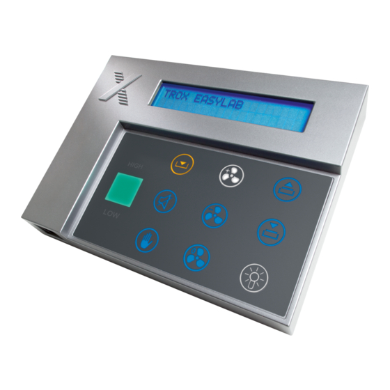
3 Product description Product overview and dimensions Product overview 40-character display Alarm sounder Sash monitoring warning display Status display (green, yellow, red) with text HIGH and LOW Connection socket for service and commissioning device ... -
Page 6: Functional Description And Technical Data
3 Product description Functional description and technical data Functional description The required function can be selected by pressing the appropriate button. The BE-LCD-01 control panel is used to display • Selection of the operating mode and control the most critical aerodynamic functions of a fume cupboard or a room. -
Page 7: Transport, Storage And Packaging
4 Transport, storage and packaging 5 Operation · Fume cupboard control Delivery check Storage Check delivered items immediately after arrival for If you need to store the control panel temporarily, transport damage and completeness. In case of any make sure that the following conditions apply: damage or an incomplete shipment, inform the •... -
Page 8: Basic Functions
5 Operation · Fume cupboard control Basic functions 40-character status display Text display of Three-colour status display fume cupboard Green, yellow, red combined with text LOW and operating states HIGH and faults. Display • Green texts → p. 11 Normal operation, fume cupboard functionally onwards reliable The display of... -
Page 9: Additional Functions
5 Operation · Fume cupboard control Operating mode default setting Additional functions In standard mode all function button fields for all Depending on the configuration and operating available functions are indicated as blue symbols mode default setting additional displays and (i.e. -
Page 10: Automatic Sash Device
5 Operation · Fume cupboard control Overriding operating mode defaults set Automatic sash device by the central BMS These buttons are used to control the automatic Operating mode default settings from the central sash device. BMS or from the room control panel can be The buttons can be used only if an automatic sash overridden on the control panel for the fume device has been configured. -
Page 11: Operating States, Alarm Messages, Fault Displays
5 Operation · Fume cupboard control Operating states, alarm messages, fault displays Operating states Code State Actual state, explanation Actions, remedial measures UPS, battery The connected power supply has failed. The control Eliminate the cause of the power operation is maintained by the battery pack. failure. - Page 12 5 Operation · Fume cupboard control Operating states, alarm messages, fault displays Alarm messages Code State Explanation Actions, remedial measures Volume flow Check the actuator and the The volume flow rate exceeds the setpoint value. rate too high controller. Volume flow Check the pressure.
- Page 13 5 Operation · Fume cupboard control Operating states, alarm messages, fault displays Controller faults Code Message Explanation Actions, remedial measures The supply voltage is too low. The sensors and 24 V Check the power supply to the actuators are no longer supplied with sufficient undervoltage system.
-
Page 14: Operation · Room Control
5 Operation · Room control The BE-LCD-01 control panel is used to display The basic functions are available for all and control the most critical aerodynamic and fume cupboards. Other functions may be safety-related functions of an EASYLAB available depending on the configuration controlled room. -
Page 15: Basic Functions
5 Operation · Room control Basic functions Acoustic alarm acknowledgement This button is used to acknowledge and Three-colour status display reset an acoustic alarm. Green, yellow, red combined with text LOW and HIGH Warning: Diversity control is active • Blinking display The fume cupboards are affected by diversity control. -
Page 16: Additional Functions
5 Operation · Room control Operating mode default setting Additional functions In standard mode all function button fields for all Depending on the configuration and operating available functions are indicated as blue symbols mode default setting additional displays and (i.e. not active). Activate the special operating function buttons may be available. -
Page 17: Overriding Operating Mode Defaults Set By The Central Bms
5 Operation · Room control Overriding operating mode defaults set No override option for the room operating by the central BMS mode The central BMS can be configured to block Operating mode default settings from the central the override function on the room control panel BMS can be overridden on the control panel for the temporarily or permanently. -
Page 18: Operating States, Alarm Messages, Fault Displays
5 Operation · Room control Operating states, alarm messages, fault displays Operating states Code State Actual state, explanation Actions, remedial measures UPS, battery The connected power supply has failed. The control Eliminate the cause of the power operation is maintained by the battery pack. failure. - Page 19 5 Operation · Room control Operating states, alarm messages, fault displays Configuration faults Code Message Explanation Actions, remedial measures Have the correct software version Software Not all controllers have the same software version installed by the Service version installed. department. No.
- Page 20 5 Operation · Room control Operating states, alarm messages, fault displays Local controller hardware faults Code State Explanation Actions, remedial measures The supply voltage is too low. The sensors and 24 V Check the power supply to the actuators are no longer supplied with sufficient undervoltage system.
-
Page 21: Mounting
6 Installation and electrical wiring For installation, wiring, and commissioning For any wiring work follow the national and local observe the recognised technical regulations, regulations and guidelines for electrical especially safety and accident prevention installation. regulations. Danger! Important! Danger of electric shock! Do not touch any Danger of injury or of damage to electrical live components! Electrical equipment cables... -
Page 22: Mounting On An Adapter
6 Installation and electrical wiring Mounting on an adapter Right-hand side Left-hand side How to proceed frame frame 1.Create a cut-out and drill any necessary holes into the side frame or furniture wall. 2.Lay the cable for the connection of the control panel with the controller. -
Page 23: Installation To A Wall Or To Furniture
6 Installation and electrical wiring Installation to a wall or to furniture Connecting How to proceed cable 1.Create a cut-out and drill any necessary holes into the wall. 2.Lay the cable for the connection of the control panel with the controller. Take the control panel end of the cable and pull it from the wall for about 10 cm. -
Page 24: Commissioning
7 Commissioning 8 Maintenance The functions of the control panel are If two control panels are connected, the same configurable. The control panel is factory set to configuration applies to both units. allow essential functions for fume cupboard and The EasyConnect configuration software can be room control (basic setting).
Need help?
Do you have a question about the EASYLAB BE-LCD-01 and is the answer not in the manual?
Questions and answers