Table of Contents
Advertisement
Quick Links
Advertisement
Table of Contents

Related Manuals for vitro Vitrolux E


Summary of Contents for vitro Vitrolux E
- Page 1 Vitrolux E / F Preface User Manual Vitrolux E / F Page 1 of 58 Stand 5/12...
- Page 2 Vitrolux E / F User Manual Note Always keep the serial number shown on this page close to hand when contacting Vitro Laser Solutions UG. Vitro Laser Solutions UG reserved the right to make technical changes to improve the product.
- Page 3 Vitro Laser Solutions UG constantly aims to improve its products. For this reason it reserves the right to make modifications and improvements which it deems necessary.
-
Page 4: Table Of Contents
Vitrolux E / F Table of contents Table of contents 1. Safety ................... 7 1.1 For your safety ..................8 1.1.1 General information .................... 8 1.1.2 Obligations of the proprietor ................8 1.1.3 Obligations of operating personnel ..............9 1.2 Liability ................... 10 1.3 Accident prevention regulations ............ - Page 5 Vitrolux E / F Table of contents 3.2 Laser head ..................28 3.3 Scanner ................... 29 3.4 Laser optics ..................30 3.5 Motor axis ..................31 3.6 Laser system switches ................ 33 3.7 Components in the control module box ..........35 3.7 Components in the control module box ..........
- Page 6 Vitrolux E / F Table of contents 5.4 Clean air filter ................... 46 5.5 Clean interior of the system ..............46 5.6 Clean the optics ................47 6. Troubleshooting ................48 6.1 General information ................49 6.2 Errors ....................49 6.2.1 System can't be switched on ................49...
-
Page 7: Safety
Vitrolux E / F Safety 1. Safety Contents This operating manual for your laser system contains important information on installation, operation, maintenance, fault conditions and ordering spare parts. We provide this information to ensure safe, reliable operation of your laser system. -
Page 8: For Your Safety
Vitrolux E / F Safety 1.1 For your safety 1.1.1 General information In addition to safety information, this operating manual provides: a general description of the product information on installing the laser system instructions on operating the laser system instructions on maintenance and upkeep... -
Page 9: Obligations Of Operating Personnel
Vitrolux E / F Safety The proprietor must instruct users regularly (at least once a year) on the dangers of laser radiation. Warning The proprietor is finally accountable for safety. This responsibility cannot be delegated to others. 1.1.3 Obligations of operating personnel... -
Page 10: Liability
No modifications, refitting or reconstruction may be made on the laser system without authorization from the manufacturer. All reconstruction work requires written approval from Vitro Laser Solutions UG. Caution Only use original spare parts and parts subject to wear. It cannot be guaranteed that parts obtained from other sources have been constructed and produced according to the applicable load and safety requirements. -
Page 11: Accident Prevention Regulations
Vitrolux E / F Safety 1.3 Accident prevention regulations 1.3.1 General information Before starting the equipment up for the first time following assembly (new installation or assembly after transport), a safety check must be made. All the load-bearing and machine parts must be checked that they are in perfect condition. - Page 12 Vitrolux E / F Safety Caution Do not open the laser head, scan head and diode module. Particles can enter and damage the high performance optics. Opening these components annuls rights to claims under the terms of warranty In Maintenance, Set-up and Repair modes (the laser beam can be accessed) the Vitrolux C laser system complies to Laser Class 4.
-
Page 13: Protective Measures From The Operator
Never bridge or manipulate protective switches that has the consequence that the warranty expires. Risk of accident. In addition to these constructional protective measures for the laser system, Vitro Laser Solutions UG also recommends equipping the entrance doors to the laser zone with such switches. -
Page 14: Assembly And Disassembly
Vitrolux E / F Safety 1.3.4 Assembly and disassembly Only personnel involved with the assembly and disassembly work may be in the vicinity of the laser system during assembly and disassembly. Others (e.g. spectators) must be kept outside the laser zone. -
Page 15: Maintenance And Repair
Vitrolux E / F Safety 1.3.7 Maintenance and repair Carry out all the prescribed maintenance work according to the maintenance schedules. Disconnect the power supply before beginning any maintenance or repair work (switch the main switch in the to OFF and unplug the mains connector). -
Page 16: Other Points Of Danger
Vitrolux E / F Safety When plugs are disconnected, keep them dry. Always keep the doors closed (protect from damp and dirt). Check the laser system’s electrical equipment regularly. Tighten loose connections and replace damaged or scorched cable. 1.3.11 Other points of danger There are other points of danger on or around the laser system which are not immediately obvious. -
Page 17: Intended Use
Only appropriate materials may be processed. Any other use is considered unintended use. The company Vitro Laser Solutions UG is not considered liable for any damage resulting from unintended use. -
Page 18: Operation
Vitrolux E / F Safety 1.5 Operation Warning In the case of functional faults, operation must be stopped immediately! The cause of functional faults must be located immediately. If necessary, operating personnel must calling experts. Operation may only be restarted when there is absolutely no doubt about the safety of the laser system. - Page 19 Vitrolux E / F Safety Warning labels Different warning labels are provided for example at the following points: Examples of warning labels laser irradiation with open cover / bridged safety loc (2) laser class specification of entire system Warning at points with risk of crushing...
- Page 20 Vitrolux E / F Safety (5) Warning - dangerous laser irradiation (6) Warning laser irradiation with Laser Class 4 (laser diode, laser head) Warning at points with a general risk of electric shock Page 20 of 58 Stand 5/12...
-
Page 21: Transport And Installation
Vitrolux E / F Transport and installation 2. Transport and installation Contents The laser system must be transported carefully and assembled in a suitable location. The subsequent system installation requires a great deal of care and coordination and should only be performed by trained personnel from Vitro Laser Solutions UG. -
Page 22: General Information
Vitrolux E / F Transport und Installation 2.1 General information Always remain calm during transportation and installation work. Avoid any stress and hectic activity because this can lead to mistakes or even accidents. Never work alone, but ensure good, well coordinated teamwork. -
Page 23: Tilt And Shock Monitoring
Vitrolux E / F Transport und Installation 2.2.3 Tilt and shock monitoring The wooden box is equipped with a tipping bracket template and an acceleration template. The tipping bracket template can be used to read the maximum tilt angle that the wooden box was subjected to during transport. -
Page 24: Installation
Vitrolux E / F Transport und Installation 2.3 Installation Prepare the installation site for the laser system. The system must be installed on a clean, level site. Caution The foundation must have a minimum load-bearing capacity of 300-500 kg/m² depending on the type of system - see technical data. -
Page 25: Product Description
Vitrolux E / F Product description 3. Product description Contents The laser system is comprised of several components which differ according to their task, construction and behavior. All the most important information required to understand the laser system components is contained in this chapter. -
Page 26: Components Comprising The Laser System
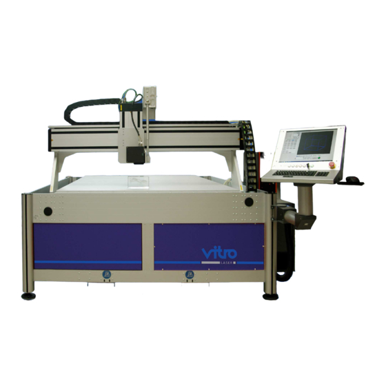
Vitrolux E / F Product description 3.1 Components comprising the laser system 3.1.1 Overview The complete processing system consists of the following components: (1) Laser head The laser beam is generated in the laser head. (2) Scan head The scan head serves to deflect the beam. -
Page 27: View Of The Components
Vitrolux E / F Product description 3.1.2 View of the components Figure 1: Overview Laser head Scan head PC Console Additional buttons and emergency stop Supply module housing with main switch Page 27 of 58 Stand 5/12... -
Page 28: Laser Head
Vitrolux E / F Product description 3.2 Laser head The scanner and laser head are both fixed to an axis. The laser crystal in the laser head is excited to emit the beam via the laser diode beam by the control unit. The laser diode beam is fed by means of a quartz glass fiber cable. -
Page 29: Scanner
Vitrolux E / F Product description 3.3 Scanner The scan head serves for the laser beam deflection in two levels. The deflection is performed by means of two galvanometer mirrors. At scan head is a focussing optic which focuses the laser beam. -
Page 30: Laser Optics
Vitrolux E / F Product description 3.4 Laser optics The laser beam emerges through the specially changeable lens. Lenses of various focal depths are available according to the application. Figure 4: Laser optics Scanner Lens with protective glass Page 30 of 58... -
Page 31: Motor Axis
Vitrolux E / F Product description 3.5 Motor axis The laser head can be moved in X, Y and Z direction. The directions of motion are: Z-axis (vertical: up +, down -) on the laser head X-axis (horizontal, right +, left -) on the X-Y plate... - Page 32 Vitrolux E / F Product description Figure 6: Motor axis Y Figure 7: Motoraxis Z Page 32 of 58 Stand 5/12...
-
Page 33: Laser System Switches
Vitrolux E / F Product description 3.6 Laser system switches The main switch for the power supply is located at the control box of the machine. Figure 8: Main switch at control box Power switch and indicator Figure 9: Power switch PC... - Page 34 Vitrolux E / F Product description On the PC console the folloxing switch and indicator are located next above the keyboard: (1) ACK white For service personnel only. Without function during normal operation (2) Cover white Unlock the security door to load and unload the machine. During the laser process, the button has no function to avoid accidentally stopped processes.
-
Page 35: Components In The Control Module Box
Vitrolux E / F Product description 3.7 Components in the control module box The control module carrier contains the axis controller for the control of X, Y, and Z axes, as well as possibly the control unit for the laser. -
Page 36: Axis Controller
Vitrolux E / F Product description 3.7.2 Axis controller The controller contains the electronics necessary for controlling the axis. Caution Axes may run on. The axes can be moved by hand when the power supply is off. Figure 12: Axis control unit... -
Page 37: Pc Console
Vitrolux E / F Product description 3.8 PC Console In the PC Console a complete PC is installed in addition to the already mentioned special keys and indicators. Through the Windows interface the pre-installed software "VitroMark" can be called, which takes over the complete control of the laser processing. -
Page 38: Operation
Vitrolux E / F Operation 4. Operation Contents The laser system may only be started up and operated by personnel who have received the necessary training and instruction, are familiar with all the operating elements and their respective functions and know when they should be used. -
Page 39: Power-On Routine
Vitrolux E / F Operation 4.1 Power-on routine Preparations 1. Check that the power supply is connected correctly. 2. Check that the Emergency Stop button is not locked. 3. Check that the doors are closed (if any). Power-on routine 1. Switch the main switch on the control module box on the side of the system in the "ON"... -
Page 40: Load/Engrave Laser Class 4
Vitrolux E / F Operation 4.2b Load/engrave laser class 4 1. Position objects tp engrave on the table. Please note the maximum possible engraving area. 2. Make sure that no unauthorized people are around, put on your safety glasses and start the laser process on the software "VitroMark". -
Page 41: Maintenance
Vitrolux E / F Maintenance 5. Maintenance Contents The laser system is largely maintenance-free, however small work must be performed by trained personnel regularly. This chapter contains information as to which parts must be maintained at and what intervals. Comprehensive maintenance measures are described step by step. -
Page 42: General Information
Vitrolux E / F Maintenance 5.1 General information Complete all maintenance work according to schedule (once a year) and document the work completed in an operation logbook. To perform the maintenance, switch on the machine and drive all axes to their starting position. -
Page 43: Lubricate Motor Axles
Vitrolux E / F Maintenance 5.3 Lubricate motor axles 5.3.1 Guide rails The rails of all axes can be lubricated by the gap between the black lips. The sealing lips even include a Teflon component and require no special maintenance. -
Page 44: Y-Axis
Vitrolux E / F Maintenance 5.3.3 Y-axis The lubrication nipples for the Y-axis are easy to access directly. It is located at the right side of the engraving area. Figure 2: Access lubrication Y-axis Lubrication nipples. Page 44 of 58... -
Page 45: Z-Axis
Vitrolux E / F Maintenance 5.3.4 Z-axis The z-axis in lubricated through 4 nipples located on both sides of the axis.. Pull off the black plastic caps and lubricate the axes using the lubrication nipples which have been exposed. Replace the plastic caps after finishing the procedure. -
Page 46: Clean Air Filter
Vitrolux E / F Maintenance 5.4 Clean air filter Fan, fitted with a dirt filter is located in the control module box. Depending on the pollution of the environment, the dirt filter should be reviewed at regular intervals to ensure a trouble-free exchange of air. -
Page 47: Clean The Optics
Vitrolux E / F Maintenance 5.6 Clean the optics If necessary, clean the protective glass of the laser lens. Clean the protective glass of the laser lens with special cleaning tissue and pure alcohol (pharmacy quality). Figure 4: Position protective glass Caution Never use scouring agents or cleaning utensils. -
Page 48: Troubleshooting
___________________________________________________________ Objectives This chapter contains information to help locate faults and explains corrective measures that are within the scope of your possibilities. Note Only use original spare parts obtained from Vitro Laser Solutions UG. Page 48 of 58 Stand 5/12... -
Page 49: General Information
Vitrolux E / F Troubleshooting 6.1 General information The normal operation of the system displays error messages / errors with accurate description on the control computer. For example - you get a message if you want to start the process of engraving, but the door of the system is not closed. -
Page 50: Software Massage „Door Open" In Closed
Vitrolux E / F Troubleshooting 6.2.5 Software massage „Door open“ in closed Possible cause: Check/fix: Broken door contact Replace or contact technician 6.2.6 Engraving moved in glass Possible cause: Check/fix: Legoboard moved/loosened Drive table on start position and check whether pilot laser appears in the right place. -
Page 51: Motive Rare To See
Vitrolux E / F Troubleshooting 6.2.9 Motive rare to see Possible cause: Check/fix: Density of dots too low For newly created motive dot pitch has been chosen may be too high and thus the density of dots is too low. -
Page 52: Technical Data
Vitrolux E / F Technical Data 7 Technical Data Contents The laser system is a complex technical system. Its components have specific properties which are necessary for safe, reliable operation. This chapter contains all the most important data concerning the individual components and entire laser system as a whole. -
Page 53: General Data
Vitrolux E / F Technical Data 7.1 General Data System Dimensions Table Engraveable Engraveable Weight (WxDxH) mm (WxD)mm area (WxDxH) area with doors Vitrolux E-S 1420x1150x1870 700x600 700x600x95 500x400x95 Ca. 400 Vitrolux E-M 1420x1450x1870 700x900 700x900x95 500x700x95 Ca. 440 Vitrolux E-L... -
Page 54: Spare Parts, Special Equipment
Vitrolux E / F Spare parts, special equipment 8 Spare parts, special equipment Contents This spare parts list contains important information on parts which may need to be replaced. This information should help to ensure you define the correct part. -
Page 55: Grease For The Axes Bearings
Vitrolux E / F Spare parts, special equipment 8.1 Grease for the axes bearings The grease specified below is suitable for greasing the axes. The grease gun ensures the grease is forced properly into the lubrication nipples. Item Tube of grease 250ml... -
Page 56: Diode Module
Vitrolux E / F Spare parts, special equipment 8.3 Diode module Replacement for the diode module. Item Diode module LDM 50W CW Luft 43000015 8.4 Lens Replacement for the standard lens. Item Lens 03-75FT-108-532 43000003 8.5 Laser safety glass The following spare part is available in order to replace a defect protecting glass (orange) of the sliding door. -
Page 57: Glass Tension Tester
Vitrolux E / F Spare parts, special equipment 8.7 Glass tension tester With the following equipment you are able to test your glass workpieces (glass tensions) before starting the laser process. In this kind you prevent a production with defectively glass. -
Page 58: Warranty
Vitrolux E / F Warranty 9 Warranty Vitro laser solutions UG provides 12 months warranty. The warranty shall lapse if following warranty seal without previous written approval by vitro laser were destroyed: Control unit Control computer (PC) Axles controller Laser head Also the improper handling and failure to comply with our policies described in the manual will void the warranty.
Need help?
Do you have a question about the Vitrolux E and is the answer not in the manual?
Questions and answers