
Related Manuals for Air King K52


Summary of Contents for Air King K52
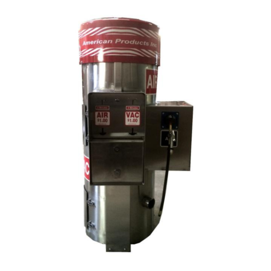
- Page 1 July, 2016 701 Frontier Way, Bensenville, IL 60106 Phone: (800) 542-3336 : (630) 350-8011 Website: AIR-KING.COM SERVICE & INSTALLATION FOR K52 & K552 VACUUM UNIT, AIR / VACUUM UNITS UNITS 1200 SERIES .
-
Page 2: Table Of Contents
July, 2016 TABLE OF CONTENTS 1. Safety Instructions Page 3 2. Introduction Page 4 3. Service & Warranty Page 5 4. General Specifications Page 6 5. Electrical Requirements Page 7 6. Mounting Instructions Page 8 7. Operating Instructions Page 9 8. -
Page 3: Safety Instructions
8. Do not use the vacuum in areas where flammable liquids may be present. WARNING: VACUUMS EQUIPPED WITH AIR COMPRESSORS (K552-750) OR VACUUMS EQUIPPED WITH REMOTE AIR SOLENOIDS (K52-9) 1. Over inflation of tires may be dangerous. Please consult your vehicle owner’s manual for proper tire inflation. - Page 4 July, 2016 INSTRUCTION The American Products / Air King Vacuum is manufactured in a variety of configurations to meet diverse customer needs. This manual has been prepared to aid service personal in installing, diagnosing and repairing American Products Inc. equipment.
-
Page 5: Service & Warranty
7) Vandalism or misuse of equipment, or tampering is not covered under warranty. 8) No returns will be accepted without a prior R.G.A. (RETURNED GOODS AUTHORIZATION). For Service Call or Write: Air King of America, Inc. 701 Frontier Way Bensenville, IL 60106 Phone# 800-542-3336... -
Page 6: General Specifications
July, 2016 GENERAL SPECIFICATIONS AIR KING MODEL K52 1. Four bag filter system for longer life. 2. Two twin stage 1.7 H.P. high performance vacuum motors. 3. 15 foot X 2 inch Industrial grade, crush resistant and clog resistant hose with nozzle at the end of the hose. -
Page 7: Electrical Requirements
Model K52 Vacuum only A. 120 Volts AC Current B. 20 AMPS Circuit Breaker C. 60 HZ Single Phase Model K52-9 Vacuum with Remote Air Solenoid A. 120 Volts AC Current B. 20 AMPS Circuit Breaker C. 60 HZ Single Phase Model K552- Vacuum with ¾... -
Page 8: Mounting Instructions
DIAMETER SEE WIRE SIZE GUIDE ON PAGE 7 FOR PROPER WIRE SEE WIRE SIZE GUIDE IN THE MANUAL FOR ELECTRICAL REQUIREMENTS K52 & K52-9 , 120 GAUGE PROPER WIRE GAUGE VAC 20 AMP CIRCUIT BREAKER, K552-750 120 VAC 40 AMP CIRCUIT BREAKER CONCRETE BASE SHOULD BE A MINIMUM OF 26 INCHES LONG BY 26 INCHES WIDE 36 INCHES HIGH. -
Page 9: Operating Instructions
B. Take two inch vacuum hose off hanger and proceed to vacuum vehicle. To operate a K552- or a K52-9 Air Vacuum and Air Vac. remote follow these instructions. A. To operate the Vacuum side insert the correct amount of coin or coins into the money slot on the right hand side of the vacuum control box. -
Page 10: Basic Maintenance
July, 2016 BASIC MAINTENANCE 1. Removal of Money Box 1200 Series Vacuum A. Remove the two medeco plug locks with keys on front of the money box face plate, rotate lock counter clockwise until you hear a click, pull lock completely out. - Page 11 July, 2016 POWER HOOK UP Remove Money Box Face plate on 1200 Series 1. Remove two bolts holding the seam cover located below the Money Box face plate at the bottom of the machine. 2. Two of the bolts are in the control box where the coin boxes set. Remove locks and money box face plate.
-
Page 12: Replacement Of Parts
July, 2016 REPLACEMENT OF PARTS Dome Removal 1200 Series Vacuums 1. The dome is held on with four allen head screws. When the screws are removed the dome may be lifted straight upward and off the unit. 2. Under the dome is where the vacuum motors, fuses and the compressor will be. Vacuum Motor replacement of the 1200 Series Vacuums 1. - Page 13 2. Insert the hose through the hose guard on the left hand side of the vacuum. Run the hose to the quick coupler on the compressor or solenoid valve on the K52-9 models. Push the quick coupler open and insert hose coupler on the end of the hose into the quick coupler.
-
Page 14: Trouble Shooting
Problem: Vacuum will not start up. Check circuit breaker in building. If the breaker in the building has not kicked out go out to the machine and do the following: 1. Check ground fault interrupter on Model K52 vacuum only. (Air vacuum model K552 do not have ground fault interrupters). If reset button is popped out this shows that there is a short of some kind in the machine. - Page 15 July, 2016 Problem: If circuit breaker in building has kicked out. For K52 & K552 models. 1. Reset breaker, try and restart machine. 2. If machine does not start you may have a bad or weak breaker. Replace breaker and try to restart machine.
- Page 16 July, 2016 VACUUM MACHINE TIMERS Timer Part # 1511 multi pulse Infitec ASCR . To adjust time and coins follow directions below: Switches 1 thru 7 Are Time setting switches. Combine number of seconds to set the time: Here Switch #3 (20 Seconds) & Switch #6 (160 Seconds) are ON for a total run time = 20+160= 180 Seconds (3 minutes) Coin setting Switches, 8, 9 &...
- Page 17 July, 2016 Timer Part # 1512 multi pulse Infitec ASCR 540. To adjust time and coins follow directions below: Combine Open Switches to select Time. Combine Closed Switches to Select Switches must lie flat towards the number Signal Count (coin). Switches must lie in seconds and toward the open.
Need help?
Do you have a question about the K52 and is the answer not in the manual?
Questions and answers