Advertisement
Available languages
Available languages
Quick Links
Dealer / Installer:
End User:
WARNING
DO NOT EXCEED Recommended towing limits. SEE VEHICLE'S OWNER'S MANUAL.
WARNING:
Use only the supplied bolts, nuts, and washers to
install this kit. All nuts and bolts are Grade 5 unless
specified otherwise
Rating when used as a weight distribution hitch with spring bars
CAUTION: The tongue weight rating of spring bars represents the capacity of a pair of bars, NOT an individual bar
32215, 32216, 32217, 32218, 33039 & 33092
Always use a pair of spring bars and be sure they are of the same weight rating and size for your trailer.
READ ALL
All Products limited to Vehicle Tow Rating, see Vehicle Owners Manual. Visit www.huskytow.com for Warranty Information / Tech Support /
Product Updates. 2021 Keystone Automotive Operations Inc. All Rights Reserved. 05/04/2021-Rev12
Assembly, Installation, Operation and
Maintenance Instructions
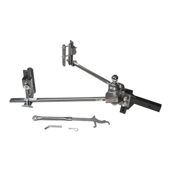
32215: CENTERLINE TS, 400-600 LBS. W/2" BALL
32216: CENTERLINE TS, 400-600 LBS. W/2-5/16" BALL
32217: CENTERLINE TS, 600-800 LBS. W/2-5/16" BALL
32218: CENTERLINE TS, 800-1200 LBS. W/2-5/16" BALL
33039: CENTERLINE TS, 1000-1400 LBS. W/2-5/16" BALL
33092: CENTERLINE TS, 800-1200 LBS. W/2-5/16" BALL W/O SHANK
Provide a copy of these instructions to the end user of this product. These
instructions provide important operating and safety information for proper usage of
this product. Demonstrate the proper use of the product with the end user. Have the
end user demonstrate that they understand the proper use of the product.
Read and follow all instructions included in this manual. Ask your Dealer / Installer for
assistance if you do not understand the proper use of the product. Never remove any
decals from the product. Failure to follow these instructions can result in injury or
death.
This product only fits trailer frames that are 4", 5", 6", 7" & 8" tall.
Part Number
32215 / 32216
32217
32218 / 33092
33039
Rating when used as a weight carry hitch without spring bars
Part Number
AND CHECK PACKAGE CONTENTS BEFORE BEGINNING
INSTRUCTIONS
Note: This system can be used on any angle tongue trailer.
Max. Tongue Weight
400-600 lbs.
600-800 lbs.
800-1200 lbs.
1000-1400 lbs.
Max. Tongue Weight
600 lbs.
INSTALLATION.
90-120 minutes
Max. Gross Trailer Weight
6,000 lbs.
8,000 lbs.
12,000 lbs.
14,000 lbs.
Max. Gross Trailer Weight
6,000 lbs.
Page-1
Advertisement

Related Manuals for Husky 32215


Summary of Contents for Husky 32215
- Page 1 Assembly, Installation, Operation and 90-120 minutes Maintenance Instructions 32215: CENTERLINE TS, 400-600 LBS. W/2” BALL 32216: CENTERLINE TS, 400-600 LBS. W/2-5/16” BALL 32217: CENTERLINE TS, 600-800 LBS. W/2-5/16” BALL 32218: CENTERLINE TS, 800-1200 LBS. W/2-5/16” BALL 33039: CENTERLINE TS, 1000-1400 LBS. W/2-5/16” BALL 33092: CENTERLINE TS, 800-1200 LBS.
- Page 2 Weigh trailer again after fully loaded and check loaded tongue and gross weight to ensure proper weight distribution hitch is being used. CAUTION! This kit is to ONLY be used with Husky weight distribution spring bars only that are designed for this particular system. Do not substitute with any other spring bars. Warning! Do not use a separate friction sway control on this unit! All Products limited to Vehicle Tow Rating, see Vehicle Owners Manual.
- Page 3 Measure Trailer Coupler & Frame Height NOTE: Changing the weight of the trailer and/or tow vehicle by adding, moving or unloading cargo may require the need to adjust how the weight distribution system is set up. IMPORTANT! Set parking brake of tow vehicle and chock the wheels of the trailer before lifting or lowering! 1.
- Page 4 Measure the Tow Vehicle For vehicles with air springs, air shocks or automatic leveling systems only: Check vehicle owner's manual or other instructions on these items. Unless otherwise indicated, air springs and air shocks should be deflated to their minimum recommended pressure BEFORE assembling and adjusting the weight distribution hitch.
- Page 5 Un-screw the 5/8-11 hex bolt until the bottom of the bolt threads are flush to the inside of the channel. Insert the shank into the receiver box. Hold CL TS head assembly onto shank as shown and align the Centerline TS head so that the hitch ball is 1” above the coupler socket. In this example, the shank will be mounted in the Inverted position (as shown).
- Page 6 Align the bottom hole on the channel to the hole on the shank and insert a 3/4” hex head bolt. Remember the hole and orientation in these instructions are an example only, yours may be different. Add hardened washers marked with “F436” on to the large head pin, and then insert into the welded bushing on the inside top of the channel.
- Page 7 The use of shims may be required to fill up the gap between the ears of the bottom plate weldment and the U channel. It is NOT necessary to have equal shims on either side. 9. Place a conical toothed washer onto a 3/4” hex bolt and then insert it through the slot in the channel All Products limited to Vehicle Tow Rating, see Vehicle Owners Manual.
- Page 8 10. The use of shims may be required to fill up the gap between the ears of the bottom plate weldment and the U channel. It is NOT necessary to have equal shims on either side. 11. Tighten 5/8” hex jam nut securely All Products limited to Vehicle Tow Rating, see Vehicle Owners Manual.
- Page 9 12. Put a conical tooth washer on the top 3/4” hex bolt followed by a 3/4” nylon lock nut. Put a 3/4” flat washer on the bottom 3/4” hex bolt followed by a 3/4” nylon lock nut. Torque the 3/4” nylon lock nuts to 380 ft-lbs.
- Page 10 14. Swing wire “D” under trunnion, and over the end of the pin. Repeat steps 9 and 10 for the other side. 15. Your CL TS system should look like this now. All Products limited to Vehicle Tow Rating, see Vehicle Owners Manual. Visit www.huskytow.com for Warranty Information / Tech Support / Page-10 Product Updates.
- Page 11 Installing Frame Brackets 16. Install frame bracket 28.5”-30.5” away from the center of ball socket on coupler All Products limited to Vehicle Tow Rating, see Vehicle Owners Manual. Visit www.huskytow.com for Warranty Information / Tech Support / Page-11 Product Updates. 2021 Keystone Automotive Operations Inc. All Rights Reserved. 05/04/2021-Rev12...
- Page 12 17. Loosen the 5/8” dog point screws so the lift bracket can be removed from the frame bracket. Use the 1/2” carriage head bolt, flat washer, lock washer and hex nut to hold the frame brackets in place. The bottom carriage head bolt should be in the hole closest to the underside of the trailer frame.
- Page 13 18. Before hooking up the trailer to the hitch ball, adjust the height of the lift bracket so that the measured distance from the ground to the bottom of the trunnion is the same (approximately) from the ground to the top surface of the lift bracket.(Dimension “A” = Dimension “B” ±1 hole) this is a starting point and you may need to make adjustments later.
- Page 14 Spring bar loading on lift brackets 22. To load the spring bar onto the lift bracket, orient the lift tool as shown below and come under the spring bar. Then, put the “finger” of the lift tool into the square hole on the lift bracket and using BOTH hands on the lift tool lift up firmly and the rotate and push the lift tool towards the trailer until the spring bar is resting completely on the lift bracket and off of the 2 pins.
- Page 15 23. Once the spring bar is resting securely on the lift bracket insert the “L” retaining pin into the square hole and secure with the hair pin clip. WARNING: Keep clear of the pivot path of all moving parts when there is tension on the spring bar.
- Page 16 Properly Adjusted System Over Adjusted System Under Adjusted System Removing the spring bar from the lift bracket 25. Make sure the tow vehicle and the trailer are on level ground and are straight. Chock the trailer wheels and engage the emergency brake on the tow vehicle. All Products limited to Vehicle Tow Rating, see Vehicle Owners Manual.
- Page 17 26. Raise the trailer tongue sufficient to ease the force required to lift the spring bar ends off of the lift brackets. Place the lift tool on the round peg on the forward side of the lift bracket and under the end of the spring bar as shown. And start pushing down on the lift tool. 27.
- Page 18 29. Remove the lift tool from under the spring bar and position it as shown below. Place the tip of the tool against the side of the frame, somewhere on the frame bracket or even on the lift bracket is fine. Then pull out on the handle (keeping hands away from the spring bar) until the spring bar falls off the lift bracket completely.
-
Page 19: Parts Listing
Parts Listing All Products limited to Vehicle Tow Rating, see Vehicle Owners Manual. Visit www.huskytow.com for Warranty Information / Tech Support / Page-19 Product Updates. 2021 Keystone Automotive Operations Inc. All Rights Reserved. 05/04/2021-Rev12... - Page 20 ITEM DESCRIPTION TOP PLATE AND CHANNEL WELDMENT LOWER PLATE WELDMENT 1200 LBS. MACHINED TRUNNION 1400 LBS. MACHINED TRUNNION 3/4-10 X 4.5" HEX BOLT 3/4" ID FLAT WASHER 5/8-11 X 2.75" HEX BOLT 5/8" ID FLAT WASHER 5/8 -11 HEX NUT 1200 LBS.
- Page 21 Follow all state, local and provincial driving and towing laws in the location you are driving in. Not following your tow vehicle, trailer, and Husky instructions/manuals can result in a fatal accident. Check Your Equipment Please refer to the MAINTENANCE section. Periodically check the condition of all your towing equipment and keep it in top condition.
-
Page 22: Maintenance
Safety Chains Can Prevent Runaway Trailer in case hitch/coupler fails. Always use safety chains when towing. Cross safety chains under coupling to prevent tongue from dropping to ground. Allow only enough slack for tight turns. Do not let safety chains drag on ground. Twist safety chains equally from hook ends to take up slack. - Page 23 Check All Trailer to Towing Vehicle Connections for Security and Operation NOTE: Surge brakes usually require a small amount of fore and aft movement for their actuating mechanism to function. Tighten the two ¾” bolts to 380 ft. lbs. torque once the head angle is set. Those surge brake actuators not designed for use with a weight distributing hitch may bind and not operate freely.
-
Page 24: Warranty Terms
Husky Towing Products and Keystone Automotive Operations Inc. with proof of purchase by the original purchaser. The original purchaser shall pay all transportation and shipping costs associated with the return of the defective product and the defective product shall become the property of Keystone Automotive Operations Inc. - Page 25 Instructions d’assemblage, d’installation, 90-120 minutes de fonctionnement et d’entretien 32215: CENTERLINE TS, 400-600 lb, avec boule de 2 po 32216: CENTERLINE TS, 400-600 lb, avec boule de 2-5/16 po 32217: CENTERLINE TS, 600-800 lb, avec boule de 2-5/16 po 32218: CENTERLINE TS, 800-1200 lb, avec boule de 2-5/16 po...
- Page 26 à répartition de poids. ATTENTION! Cet ensemble doit SEULEMENT être utilisé avec les tiges à ressort à répartition de poids Husky qui sont conçues pour ce système particulier. Ne pas remplacer par aucune autre tige à ressort. Mise en garde! Ne pas utiliser d’autres commandes antiroulis à...
- Page 27 Mesure de l’attelage de remorque et de la hauteur du châssis REMARQUE : Changer le poids de la remorque et/ou du véhicule remorqueur en ajoutant, en déplaçant ou en déchargeant de la marchandise peut nécessiter le besoin d’un ajustement du système à répartition de poids. IMPORTANT! Activer le frein de stationnement du véhicule remorqueur et caler les roues de la remorque avant le soulèvement ou l’abaissement! 1.
-
Page 28: Installation Et Configuration
Mesurer le véhicule remorqueur Uniquement pour les véhicules munis de ressorts pneumatiques, d’amortisseurs pneumatiques ou de correcteur d’assiette automatique : vérifier le guide d’utilisation du véhicule ou toutes autres directives à ce sujet. À moins d’indication contraire, les ressorts et les amortisseurs pneumatiques devraient être dégonflés à... - Page 29 Dévisser le boulon hexagonal de 5/8 po-11 jusqu’à ce que l’extrémité du filetage atteigne l’intérieur de la barre d’accouplement. Boulon hexagonal de 5/8 po-11 Insérer la tige dans le boîtier récepteur. Maintenez CL TS la tête de l’Assemblée sur la tige comme indiqué...
- Page 30 6. Alignez le trou inférieur sur le canal dans le trou de la tige et un 3/4" boulon à tête hexagonale. N’oubliez pas le trou et l’orientation dans ces instructions sont un exemple seulement, la vôtre peut être différente. Ajouter durcis rondelles marqué avec « F436 » sur le grand pin de tête et ensuite insérer dans la douille soudée à...
- Page 31 8. En utilisant une douille de 15/16 po, visser le boulon hexagonal de 5/8 po jusqu’à ce que tout l’espace de rotation disponible de la tête du CENTERLINE TS soit comblé et que la grande tige vienne s’appuyer contre la tige. Tourner ensuite de 1/4 à 1/2 tour supplémentaire. Boulon hexagonal de 5/8 po...
- Page 32 10. L’utilisation de cales peut être nécessaire pour combler l’espace entre la patte de l’assemblage soudé de la plaque inférieure et la barre en U. Il n’est pas nécessaire d’utiliser des cales de même épaisseur pour combler l’espace de chaque côté. 11.
- Page 33 12. Placer une rondelle concave à crans sur un boulon hexagonal de 3/4 po du haut, suivi d’un contre-écrou de nylon de 3/4 po. Placer une rondelle plate de ¾ po sur le boulon hexagonal de 3/4 po du bas, suivi d’un contre-écrou de nylon de 3/4 po. Coupler le contre-écrou de nylon de 3/4 po à...
- Page 34 14. Votre système CENTERLINE TS devrait maintenant ressembler à ceci. Tous les produits sont limités à l'évaluation de la capacité de remorquage du véhicule, voir le manuel du propriétaire du véhicule. Voir www.huskytow.com pour les informations sur la garantie, l'assistance technique et les mises à jour des produits. 2021 Keystone Automotive Operations Inc.
- Page 35 Installation de supports de châssis 15. Installer le support de châssis entre 28,5 po et 30,5 po à partir du centre de la douille de la boule sur le coupleur. Tous les produits sont limités à l'évaluation de la capacité de remorquage du véhicule, voir le manuel du propriétaire du véhicule. Voir www.huskytow.com pour les informations sur la garantie, l'assistance technique et les mises à...
- Page 36 16. Desserrer les vis tétons de 5/8 po afin que le support d’élévation puisse être retiré du support de châssis. Utiliser le boulon de carrosserie, la rondelle plate, la rondelle de retenue et l’écrou hexagonal de 1/2 po pour maintenir les supports de châssis en place. Le boulon de carrosserie inférieur devrait se trouver dans le trou le plus près de la face inférieure du châssis.
- Page 37 17. Avant de procéder à l’attelage de la remorque à la boule d’attache, ajuster la hauteur du support d’élévation afin que la distance mesurée à partir du sol jusqu’au bas du tourillon soit la même (ou approximativement la même) que celle mesurée à partir du sol jusqu’à la partie supérieure du support d’élévation (dimension «...
- Page 38 20. Élever l’avant de la remorque et l’arrière du véhicule remorqueur, jusqu’à ce que les embouts des tiges à ressort soient d’équerre ou à peu près de niveau avec la surface d’appui des supports de chargement. Chargement de la tige à ressort sur des supports d’élévation 21.
- Page 39 22. Lorsque la tige à ressort est solidement appuyée sur le support d’élévation, insérer la goupille de retenue en « L » dans le trou carré et fixer en place à l’aide de la pince de fixation. AVERTISSEMENT : Se tenir à l’écart de la trajectoire du pivot de toutes pièces mobiles, lorsqu’une tension est exercée sur la tige à...
- Page 40 Retirer la tige à ressort du support d’élévation 24. S’assurer que le véhicule remorqueur et la remorque sont sur une surface de niveau et droits. Caler les roues de la remorque et enclencher le frein de secours du véhicule remorqueur. Tous les produits sont limités à...
- Page 41 25. Soulevez le timon de la remorque suffisante pour soulager la force nécessaire pour soulever la barre de printemps se termine hors des crochets de levage. Placez l'outil de levage sur la cheville ronde sur la face avant de la console de ascenseur et sous l'extrémité de la barre de ressort comme indiqué.
- Page 42 même sur le support d’élévation. Tirer ensuite sur la poignée (en gardant les mains éloignées de la tige à ressort) jusqu’à ce que celle-ci se détache complètement du support d’élévation. Tous les produits sont limités à l'évaluation de la capacité de remorquage du véhicule, voir le manuel du propriétaire du véhicule. Voir www.huskytow.com pour les informations sur la garantie, l'assistance technique et les mises à...
- Page 43 Liste des pièces Tous les produits sont limités à l'évaluation de la capacité de remorquage du véhicule, voir le manuel du propriétaire du véhicule. Voir www.huskytow.com pour les informations sur la garantie, l'assistance technique et les mises à jour des produits. 2021 Keystone Automotive Operations Inc.
- Page 44 Article DESCRIPTION Plaque supérieure et assemblage soudé de la barre d'accouplement Assemblage soudé de la plaque inférieure Tourillon usiné, 1200 lb Tourillon usiné, 1400 lb Boulon hexagonal 3/4-10 X 4,5 po Rondelle plate 3/4 po DI Boulon hexagonal 5/8-11 X 2,75 po Rondelle plate 5/8 po DI Écrou hexagonal 5/8 -11 Goupille de retenue en D 3/8 po, 1200 lb...
- Page 45 Respecter toutes les lois d’états, locales et provinciales en matière de conduite et de remorquage en vigueur dans la région. Le non-respect des instructions ou des manuels du véhicule remorqueur, de la remorque et de Husky peut causer un accident mortel.
- Page 46 Recommandations des fabricants du véhicule remorqueur et de la remorque Passer en revue le manuel de l’utilisateur du véhicule remorqueur et de la remorque pour connaître les recommandations spécifiques, les capacités et les exigences. Passagers dans les remorques Aucun passager ne doit se trouver dans la remorque au moment du remorquage. La plupart des états et provinces veillent au respect de ce règlement.
- Page 47 évident. • En cas de doute concernant le degré d’usure, appeler toujours la ligne de soutien technique de Husky Tow pour en discuter avec un conseiller technique formé. Tous les produits sont limités à l'évaluation de la capacité de remorquage du véhicule, voir le manuel du propriétaire du véhicule. Voir www.huskytow.com pour les informations sur la garantie, l'assistance technique et les mises à...
- Page 48 Vérifier tous les raccordements de la remorque et du véhicule remorqueur aux fins de sécurité et de fonctionnement REMARQUE : les freins à inertie exigent habituellement une petite quantité de mouvement avant et arrière pour assurer le fonctionnement de leur mécanisme de commande. Serrer les deux boulons de ¾...
-
Page 49: Modalités De La Garantie
Tout produit qui fait l’objet d’un défaut de fabrication ou de matériau sera remplacé ou réparé à la discrétion de Husky Towing Products et de Keystone Automotive Operations Inc. avec une preuve d’achat présentée par l’acheteur original. L’acheteur original paiera tous les coûts de transport et d’expédition liés au retour du produit défectueux et le produit défectueux deviendra la propriété...
Need help?
Do you have a question about the 32215 and is the answer not in the manual?
Questions and answers