
Related Manuals for Critikon DINAMAP 8100

Summary of Contents for Critikon DINAMAP 8100
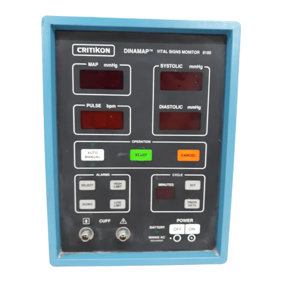
- Page 1 DINAMAP ™ Portable Adult/Pediatric and Neonatal Vital Signs Monitor Model 8100 Operation Manual...
- Page 2 LIST OF EFFECTIVE PAGES U.S. Patent 4,349,034 U.S. Patent 4,360,029 U.S. Patent 4,501,280 U.S. Patent 4,546,775 Patent Pending CAUTION: Federal (U.S.A.) law restricts this device to sale by or on the order of a health care practitioner. The content of this document including all figures and drawings is proprietary information of Johnson &...
-
Page 3: Table Of Contents
CONTENTS List of Effective Pages ............List of Illustrations ..............iv List of Tables................ iv Frontispiece ................v SECTION 1. INTRODUCTION General ................1-1 Manual Purpose..............1-1 Manual Effectivity...............1-1 Reissues...............1-1 Change Information Sheets ..........1-1 Errors, Omissions, Incorrect Data.........1-1 Related Publications ............1-2 Instruction Labels ............1-2 Service Manual.............1-2 Service Policy ..............1-2 Extended Warranties ............1-2... - Page 4 Basic Operating Cycle ............4-3 Operating Modes ...............4-4 Manual Mode..............4-4 Auto Mode ..............4-4 Neonatal or Adult/Pediatric Monitoring ......4-5 Systolic Search.............4-5 Undetermined Systolic and Diastolic Pressures....4-6 CONTENTS SECTION 5. INSTALLATION AND OPERATION Continued Unpacking ................5-1 Content Checklist ............5-1 Missing Items ..............5-1 Indications and Contraindications ........5-1 Installation and Initial Setup ..........5-2 Electrical and Hose Connections........5-2 Operating Warnings, Precautions, and Notes ....5-5...
- Page 5 Calibration................6-7 Blood Pressure Calibration Check ........6-7 Cuff and Hose Leak Check ..........6-9 Performing a Cuff and Hose Pneumatic Leak Check ...6-9...
-
Page 6: List Of Tables
LIST OF Figure No. Title Page ILLUSTRATIONS Frontispiece.............v Front Panel Controls and Indicators .....3-4 Rear Panel Controls and Indicators....3-11 Determination Sequence ......4-2 Basic Operating Cycle ........4-3 Low Amplitude Waveform Diagram ....4-6 Recommended Cuff Placement....5-3 Cover Removal..........6-4 Open AC Line Fuse Compartment ....6-5 Remove Fuse Holder........6-5 Remove Fuse from Fuse Holder....6-6 Replace AC Line Fuse and Fuse Holder ..6-6... - Page 7 DINAMAP™ Portable Vital Signs Monitor, Model 8100...
-
Page 8: Introduction
SECTION 1. INTRODUCTION GENERAL The DINAMAP™ Portable Vital Signs Monitor 8100 is designed to noninvasively and automatically measure systolic and diastolic pressure, mean arterial pressure (MAP), and pulse rate for neonatal or adult/pediatric patients. Results are displayed on large, easy-to-read digital displays. -
Page 9: Related Publications
The warranty for this product is enclosed with the product in the shipper carton. All repairs on products under warranty must be performed or approved by Critikon Company LLC personnel. Unauthorized repairs will void the warranty. Products not covered by warranty should be repaired only by qualified electronics service personnel. -
Page 10: Service
Customer Support and a representative will assist you. Estimates for non-warranty repairs are provided at no charge; however, the product must be sent to the Critikon Service Center in order to provide you with an estimate. To facilitate prompt service in cases where the product has external chassis or case damage, please advise the Customer Support representative when you call. -
Page 11: Insurance
A loaner unit is provided at no charge during the service life of the product when the repair service is performed by Critikon. Within 48 hours of your request, a loaner will be shipped to your facility. Critikon will pay shipping charges for a loaner sent to the customer for product repairs under the warranty. - Page 12 Replacements such as hoses, sensors, etc. must be A C C E S S O R I E S purchased from Critikon at 1-77-274-8456. Please have the 4-digit Reorder/Product Code of the item you wish to order, your purchase order and account number available.
-
Page 13: Product Description
SECTION 2. PRODUCT DESCRIPTION OVERVIEW The DINAMAP™ Portable Monitor, Model 8100, is designed to provide operator convenience and reliability when monitoring vital signs. Features that enhance the DINAMAP™ Monitor's operation follow. UNIQUE OPERATING FULLY AUTOMATIC PATIENT SELECTION AND FEATURES MONITORING Senses cuff size and switches automatically from adult/pediatric monitoring to neonatal monitoring or vice versa. -
Page 14: Unique Operating Features
UNIQUE OPERATING AUTOMATIC PRESSURE ZEROING FEATURES (Cont.) Microcomputer automatically establishes the zero pressure reference before each determination, thus reducing the need for constant calibration verification. PRIOR DATA RECALL Recalls from up to 100 previous determinations during the last 99 minutes of elapsed time. DIGITAL DISPLAYS Large, easy-to-read digital displays (via high intensity LEDs) provide continuous readout of the most recent... - Page 15 Optional Accessories Cont. Reorder No. DISPOSA-CUF™ Soft Neonatal Blood Pressure Cuffs Neonatal #1, 3 cm-6 cm 2521 Neonatal #2, 4 cm-8 cm 2522 Neonatal #3, 6 cm-11 cm 2523 Neonatal #4, 7 cm-13 cm 2524 Neonatal #5, 8 cm-15 cm 2525 DISPOSA-CUF™...
- Page 16 Optional Accessories Cont. Reorder No. Calibration Kit 8886 Hose (light blue), Pneumatic, 8 foot (Neonate Cuffs) 8840 Hose (blue), Pneumatic, 24 foot (Adult/Pediatric only) 8842 Model 902 Mobile Stand 0902 DINAMAP™ BP Accessory Pole 3207 DINAMAP™ BP Accessory 3208 Base DINAMAP™...
-
Page 17: Physical Description
SECTION 3. PHYSICAL DESCRIPTION The DINAMAP™ Portable Monitor Model 8100 is a microprocessor controlled noninvasive device housed in a blue plastic case. Performance and technical specifications for the Model 8100 follow. Tables 3-1 and 3-2 contain a general physical description of the monitor's controls, indicators, connectors, and operating requirements. -
Page 18: Performance Specifications
PERFORMANCE PULSE RATE DETERMINATION SPECIFICATIONS Adult/Pediatric (Maximum) 200 bpm Continued (Minimum) 40 bpm Neonate (Maximum) 220 bpm (Minimum) 40 bpm PULSE RATE ACCURACY ± 3.5 percent DETERMINATION TIME 20 seconds to 45 seconds typical; 120 seconds maximum OVERPRESSURE CUTOFF Adult/Pediatric 300 ± 30 mmHg 235 ±... -
Page 19: Electrical
TECHNICAL Electrical SPECIFICATIONS POWER CABLE (cont) Domestic–10 foot detachable blue-jacketed 16 gauge terminated with 3-prong hospital grade plug. International–10 foot detachable blue-jacketed 16-gauge unterminated. BATTERY 12 volt, 2.4 amp-hours. Six hour minimum operation (5 minute auto cycle w/adult cuff at 25 degrees C) with full charge (see Table 6-1, Battery Charging Characteristics). - Page 20 Figure 3-1. Model 8100 Front Panel Controls and Indicators TABLE 3-1 MODEL 8100 FRONT PANEL CONTROLS AND INDICATORS ITEM NAME FUNCTION CUFF This illuminated (amber) indicator signifies that a determination is in progress. kPa (amber) indicator lights only if internal kPa jumper is installed.
- Page 21 TABLE 3-1 MODEL 8100 FRONT PANEL CONTROLS AND INDICATORS — Continued ITEM NAME FUNCTION This 3-digit red LED display shows mean mmHg arterial pressure. In addition this display: flashes cuff pressure during deflation time. shows MAP alarm limits (see Item 18, SELECT).
- Page 22 TABLE 3-1 MODEL 8100 FRONT PANEL CONTROLS AND INDICATORS — Continued ITEM NAME FUNCTION CANCEL Visual and audible alarms may be Cont. canceled during wait time and the displays will maintain the last determined values. This grey momentary pushbutton switch increments the MINUTES display when in auto mode.
- Page 23 TABLE 3-1 MODEL 8100 FRONT PANEL CONTROLS AND INDICATORS — Continued ITEM NAME FUNCTION PRIOR Depression of this switch will cause the DATA monitor to display the data from the previous determination and the elapsed time (in minutes) since the determination was made.
- Page 24 TABLE 3-1 MODEL 8100 FRONT PANEL CONTROLS AND INDICATORS — Continued ITEM NAME FUNCTION This grey momentary pushbutton switch LIMIT displays the current low alarm limit that you select (SELECT switch). If you push and hold this switch, you will cause the display to step through the entire range of low limit settings (settings overlapping the high limit will not be displayed.) The new...
- Page 25 TABLE 3-1 MODEL 8100 FRONT PANEL CONTROLS AND INDICATORS — Continued ITEM NAME FUNCTION SELECT This grey momentary pushbutton switch selects the alarm limits to be displayed. Depressing the switch the first time: blanks all displays except SYSTOLIC, allows the HIGH LIMIT and LOW LIMIT switches to be used to display (set) the high and low systolic alarm limits in the SYSTOLIC display.
- Page 26 TABLE 3-1 MODEL 8100 FRONT PANEL CONTROLS AND INDICATORS — Continued ITEM NAME FUNCTION AUTO/ This white momentary pushbutton switch MANUAL with adjacent LED indicators controls and Cont. indicates the mode of operation for the monitor. Pressing this switch changes the operating mode as indicated by the associated green LED.
- Page 27 WARNING For continued protection against fire hazard, replace only with same type and rating of fuse. Disconnect supply before servicing. AVERTISSEMENT Couper l'alimentation avant l'entretien et le depannage. 3AG, 0.5A, 250V Figure 3-2. Model 8100 Rear Panel Controls and Indicators TABLE 3-2 MODEL 8100 REAR PANEL CONTROLS AND INDICATORS...
-
Page 28: Functional Description
SECTION 4. FUNCTIONAL DESCRIPTION The DINAMAP™ Portable Monitor, Model 8100, is a fully portable, microprocessor controlled, noninvasive device that automatically measures systolic pressure, diastolic pressure, mean arterial pressure (MAP), and pulse rate for neonates, children, and adults using the oscillometric technique. -
Page 29: Determination Sequence
DETERMINATION The monitor deflates the cuff one step each time it detects S E Q U E N C E two pulsations of relatively equal amplitude. Time between Continued deflation steps depends on the frequency of these matched pulses (pulse rate of patient). However, if the monitor is unable to find any pulse within 1.6 seconds, it deflates to the next step. -
Page 30: Basic Operating Cycle
MAXIMUM-MINIMUM RANGES TABLE 4-1. MAXIMUM AND MINIMUM DETECTABLE PRESSURE Continued Parameter Neonatal Adult/Pediatric Systolic Pressure 190 mmHg 245 mmHg 30 mmHg 30 mmHg Diastolic Pressure 160 mmHg 210 mmHg 10 mmHg 10 mmHg MAP (Mean 170 mmHg 225 mmHg Arterial Pressure) 20 mmHg 20 mmHg Pulse Rate... -
Page 31: Operating Modes
OPERATING MODES Manual Mode The manual mode is the normal initial mode of operation for the monitor, the mode entered automatically after pressing the POWER ON switch. Default alarm limits automatically activate at power-ON but may be changed by the operator to suit any particular patient. -
Page 32: Neonatal Or Adult/Pediatric Monitoring
OPERATING MODES A determination in progress may be canceled at any time by Continued pressing the CANCEL switch. This action deflates the cuff and begins a new wait cycle (as displayed in the CYCLE MINUTES display). Any operator set alarm limits are unaltered. -
Page 33: Pressures
If this condition occurs while in auto mode, the monitor will attempt one or more additional determinations after a 15 second delay. ADULT NEONATE SYS/DIA SYS 120 SYS 80 NORMAL DIFFERENCE MAP 86 MAP 47 PRESSURE 50mmHg DIA 70 DIA 30 SYS 20 SYS/DIA PRESSURE... -
Page 34: Content Checklist
Remove the monitor from the carton and inspect the monitor. Retain all shipping materials for inspection by the carrier in case of shipping damage or for reshipment, if necessary, to Critikon Company, LLC. Account for and inspect each item before discarding or storing the shipping materials. -
Page 35: Installation And Initial Setup
INSTALLATION AND Electrical and Hose Connections INITIAL SETUP If there is no apparent external damage to the monitor, follow these steps. With monitor power off: 1. Check the voltage rating stamped on the serial number plate attached to the bottom of the monitor and make sure it matches the line voltage of the receptacle to be used. -
Page 36: Cuff-To-Hose Compatibility
NEONATE ADULT/PEDIATRIC Figure 5-1. Recommended Cuff Placement WARNING Do not place the cuff on an extremity being used for intravenous infusion, or any area where circulation is compromised or has the potential to be compromised. 5. Measure the limb of the patient and select the proper cuff size according to the size marked on cuff or cuff package. - Page 37 6. Connect the cuff to the hoses. Thread the cuff connectors onto the hose connectors. DO NOT OVERTIGHTEN. WARNING It is mandatory that the 8-foot hose (Light Blue, Reorder No. 8840) be used with neonatal cuffs and the 12 or 24 ft. hoses (Blue, Reorder No.
-
Page 38: Operating Warnings, Precautions, And Notes
Vital signs may very likely be inaccurate if you use cuffs, hoses or accessories other than those provided by Critikon Company, LLC. The monitor will not operate effectively on patients who are experiencing convulsions or tremors. - Page 39 PRECAUTIONS Cont. Place the monitor on a rigid, secure surface or attach securely with the pole clamp. If the integrity of the electrical ground is in doubt, disconnect the power cord from the power source, and operate the monitor using internal battery.
-
Page 40: Operating Procedures
PRECAUTIONS Cont. The pulse rate displayed by the DINAMAP™ Monitor may differ from heart rate displayed by an ECG monitor because the DINAMAP™ Monitor measures actual peripheral pulse. Occasionally, electrical signals at the heart do not produce a peripheral pulse. Similarly, if a patient's beat-to-beat pulse amplitude varies significantly (e.g., pulsus alternans, atrial... -
Page 41: Set Alarm Limits Procedure
POWER-ON 3. Set the systolic, MAP, pulse, and diastolic alarm limits if PROCEDURE it is desired that these limits be changed from the Cont. default values. TABLE 5-2. DEFAULT ALARM LIMITS ADULT NEONATE SYSTOLIC high limit 240 mmHg 240 mmHg SYSTOLIC low limit ** MAP high limit 140 mmHg... - Page 42 SET ALARM LIMITS 2. Momentarily press HIGH LIMIT to display the current PROCEDURE Cont. systolic high limit. Press and hold HIGH LIMIT to cause the monitor to increment through the high alarm range settings. Release the HIGH LIMIT switch at the desired setting.
-
Page 43: Manual Mode
SET ALARM LIMITS 10. Momentarily press SELECT to enable the DIASTOLIC PROCEDURE Cont. display to show the diastolic alarm limits. All other displays will be blanked and the DIASTOLIC display will show zero (or the diastolic value of the previous determination). -
Page 44: Alarm Indications And Interpretation
ALARM INDICATIONS All alarm indications are accompanied by an audio signal A N D unless the SILENCE switch is in the ON state. In the INTERPRETATION SILENCE (ON) state, an alarm condition (other than a microprocessor system failure) is indicated by the flashing yellow LED indicator. - Page 45 TABLE 5-3. SYSTEM ALARMS SUMMARY TABLE P U L S E A L L L E D C A N C E L PROBABLE CAUSE O P E R A T O R DISPLAY O T H E R INDICATORS SWITCH ACTION D I S PL A Y S...
- Page 46 5-13...
-
Page 47: Troubleshooting
TROUBLESHOOTING The DINAMAP™ Portable Monitor Model 8100 has been designed to provide safe and reliable operation in medical environments. As with all medical devices, if the accuracy of any determination value is questionable, first check the patient's vital signs by alternate means and then check the monitor. -
Page 48: Excess Determination Time Alarm (844)
TROUBLESHOOTING Excess Determination Time Alarm (844) Cont. This alarm is indicated by an alarm tone and a flashing 844 in the PULSE display. The alarm is generated if determination time exceeds 120 seconds, which is usually caused by excessive patient movement and/or erratic pulse rate. -
Page 49: Monitor Will Not Power-On
Monitor Will Not Power-On This condition could be caused by a depleted battery. Check fuse. Attach unit to AC power source. If problem persists, refer to qualified service personnel. Monitor Displays Extremely High Readings This condition could be caused by using a cuff that is too large or by the cuff being positioned above heart level. -
Page 50: Maintenance And Calibration
SECTION 6. MAINTENANCE AND CALIBRATION MAINTENANCE Cleaning The only maintenance routinely required is that the monitor and accessories are kept clean and are handled and used according to the instructions provided here and in the Service Manual (328-370). The exterior of the monitor may be wiped clean with a cloth slightly dampened with mild detergents. -
Page 51: Battery Charging
MAINTENANCE Battery Charging Continued To charge battery simply attach AC line power cord to the monitor's rear panel line power connector THEN plug the opposite end into an appropriate AC receptacle. The battery will charge regardless of the position of any other switches (see following table for battery charging characteristics). -
Page 52: Battery Removal And Replacement
Battery Removal and Replacement It is best to keep the battery charged as fully as is practical and never store the monitor with the battery in a discharged condition. When the battery will no longer take a charge, remove it and replace it with one of the same part number (320-378) as outlined below. -
Page 53: Replacement Of Line Power Fuses
Figure 6-1. Cover Removal Changing Fuses The monitor contains three fuses. Two AC line power fuses are contained in the power entry module. One battery fuse is contained on the power supply board and is accessible only by qualified service personnel. Replacement of Line Power Fuses At the rear of the monitor, remove the power cord (if one is attached). - Page 54 MAINTENANCE Continued Figure 6-2. Open AC Line Fuse Compartment Using the same tool, pry out each fuse holder as shown in Figure 6-3. Figure 6-3. Remove Fuse Holder Remove each fuse from its fuse holder as shown in Figure 6-4. and inspect it for a burned or broken filament. If the filament appears to be intact, check it for continuity with an ohmmeter.
-
Page 55: Replacement Of Battery Fuse
MAINTENANCE Continued Figure 6-4. Remove Fuse From Fuse Holder Replace the fuse and fuse holder as shown in Figure 6-5. Make sure that the arrows on the outward facing ends of the fuse holders are pointing in the same direction as the arrows on the inside of the cover plate. -
Page 56: Calibration Check Setup
CALIBRATION Calibration of the monitor should be checked at least once a year or when there is doubt about the validity of the pressure readings. CAUTION Calibration equipment should always be kept dry and free of particulate matter. Moisture or foreign substances introduced into the pneumatic system can cause damage to the unit. - Page 57 BLOOD PRESSURE To perform a calibration check, follow these procedural CALIBRATION CHECK steps: Continued 1. Obtain the calibration kit (Reorder No. 8886) supplied with the unit. 2. Connect a mercury manometer (Baumanometer 300, or equivalent) to the monitor using the parts supplied with the calibration kit as shown in Figure 6-6.
-
Page 58: Calibration Check Pressure Levels
BLOOD PRESSURE CALIBRATION CHECK Continued TABLE 6-2 CALIBRATION CHECK PRESSURE LEVELS MANOMETER MAP DISPLAY INDICATED PRESSURE LEVEL 200 mmHg, ± 1 mmHg 200 mmHg, ± 5 mmHg 150 mmHg, ± 1 mmHg 150 mmHg, ± 4 mmHg 100 mmHg, ± 1 mmHg 100 mmHg, ±... - Page 59 CUFF AND HOSE LEAK CHECK Continued CUFF DIGITAL MANOMETER "Y" ADAPTER CALIBRATION Figure 6-7. Cuff and Hose Leak Check Setup 6-10...
Need help?
Do you have a question about the DINAMAP 8100 and is the answer not in the manual?
Questions and answers