Table of Contents
Advertisement
Quick Links
Advertisement
Table of Contents

Subscribe to Our Youtube Channel
Related Manuals for Kaindl RMS-CNC

Summary of Contents for Kaindl RMS-CNC
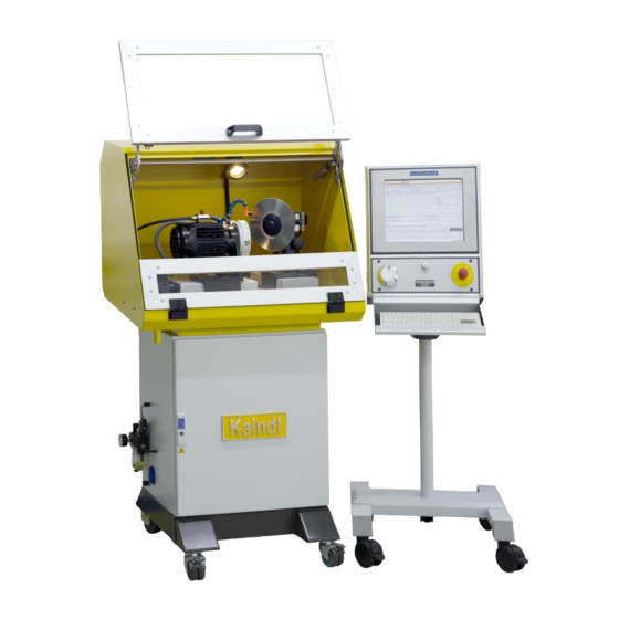
- Page 1 OPERATING MANUAL FOR CIRCULAR KNIFE SHARPENING MACHINE RMS-CNC Original operating manual Kaindl-Schleiftechnik REILING GmbH, Remchinger Str. 4, D-75203 Königsbach-Stein, Germany Tel.: +49 7232/4001 -0, Fax.: +49 7232/4001 -30, Internet: www.kaindl.de, E-Mail: info@kaindl.de...
-
Page 2: Table Of Contents
Transport / Dimensions and weight Set up and connection of the control unit Environmental conditions / Safety advise / Directed use Structure of RMS-CNC / Coolant equipment / air spindle (optional) Hardware components of the CNC-control Technical data Power-on the machine... -
Page 3: Ec-Declaration Of Conformity
DECLARATION OF CONFORMITY The manufacturer: Kaindl-Schleiftechnik Reiling GmbH Remchinger Straße 4 75203 Königsbach-Stein Germany declares that the machine descirbed hereafter: Type: is conform to the following EC-Machine instruction (2006/42/EC) EC-Instructions: EC-Low current requirement (73/23/EC) EC-Instruction EMV (89/336/EC) Applied harmonised norms:... -
Page 4: Duty Of Taking Care By The User / Demands Of The Operating Personnel / Transport / Dimensions And Weight
The RMS-CNC meets the stat of the art and grants a maximum of safety. The safety can only be achieved in daily work, when all neccessary steps are taken. It is the duty of taking care by the user to plan and control these steps. -
Page 5: Set Up And Connection Of The Control Unit
SET UP AND CONNECTION OF THE CONTROL UNIT Before placing the machine at its final position on the floor, screw in the machine feet from below. Please pay attention that the machine is alignment horizontal. Please check with a bubble level. Pay attention, that the space for the machine grants a vibration free operation. - Page 6 Main plug Plug for jogwheel Plug emmergency 25 Pole Sub-D plug with pins 25 Pole Sub-D plug with socket...
-
Page 7: Directed Use
These knifes may as sharp as a razot knife. Careless handling can cause serious incised wounding DIRECTED USE The circular knife and profiled knife sharpening machine RMS-CNC is exclusively destined for sharpening of circular knifes or profiled knifes with a max. dia. of 350 mm respectively a max. radius of 1 75 mm. - Page 8 RMS-CNC STRUCTURE OF THE Coolant hose Knife holding fixture Ball valve Knife spindle locking Axis Y (S) Axis Z (Y) Axis X Angle clamping Circular knife lynette Angle scale Grinding motor Dresser unit (Electro spindle) Manual length adjustment...
- Page 9 1 0. DESCRIPTION OF THE COOLANT EQUIPMENT Machine connection Pistol connetion Machine outlet Pump vent screw 3 Step switch...
- Page 10 The coolant container must be filed 3/4 of its total volume with coolant. Subsequently, the pump must be vented. The minimum filing height is the upper edge of the pump. The coolant equipment is connection to the machine by means of the blue electrical socket.
- Page 11 The standard equipment if the RMS-CNC includes an (Ø 1 00 mm) aerosol suction connection. The RMS-CNC is equipped with two doors halves that lock during the automatic operation mode when the program is running. If the door is open, switching between the operation modes manual to automatic or from manual to MDI is not possible, respectively, upon opening the door, the operation mode will switch back to manual.
- Page 12 11 . CNC- HARDWARE COMPONENTS OF THE CONTROL The IPC control is equipped with a touch screen, The buttons on the user interface are actuated by means of touching them. The ICP control is equipped with a keyboard with touch pad in place of a mouse. The USB 2.0 interface is used to secure the date of your CNC-Programs by mean of a USB stick.
-
Page 13: Technical Data 1
1 2. TECHNICAL DATA Grinding area of circular blade: from Ø 50 to Ø 350 mm Grinding area of punch blade: from 50 to 1 75 mm radius Grinding motor (E-spindle): 1 ~ 230 V / 50-60 Hz, 0,37 KW, 2790 r/pm Connected load with controls: 1 ~ 230 V / 50-60 Hz, 1 ,2 KW Number of numerical axes:... - Page 14 Turning on the machine After the controls boot, you see the start-up display. Two machine configurations are available: 1 . Kaindl-ROUND: is a two axes configuration for grinding of circular blades or inner cylindrical grinding. 2. Kaindl-RMS-CNC: is a three axes configuration for grinding of punch blades.
- Page 15 1 4. TKEMC GRAPHIC USER INTERFACE TKEMC has been adapted by us accordingly to the machine. The menus and functions are described here in after. , as well as brief instructions regrarding the keyboard functions and the individual menus, as well as the G- and M-Codes. After the software has started, the machine must be switched on with the F2 key.
- Page 16 1 5. TKEMC DESCRIPTION OF THE MENU There are many useful functions and aides in the TKEMC menus, which facilitate your work, respectively the search for error diagnosis. The relevant functions are described here: File > Open Opens a CNC program File >...
- Page 17 1 6. FUNCTIONS FOR THE PROGRAM SEQUENCE The functionality of the program sequence is almost self-indicating. Open Opens the dialogue for selection of an existing CNC program Execute Starts the selected CNC program Pause Stops the running CNC program with which ... Continue Starts the stopped CNC program Step...
- Page 18 1 7. OPERATION ALIGNMENT OF THE CIRCULAR OR PROFILED KNIFE By opening the star head screw (1 ), you can set the grinding angle. For less than 1 20 mm, the blade angle is set counter-clockwise; over 1 20 mm, in a clockwise direction. By opening the star head screw (2), you can move the entire take-up stand in the Z direction and re-clamp.
-
Page 19: Fixation Of A Circular- Or Profiled Knife
1 8. FIXATION OF A CIRCULAR OR PROFILED KNIFE Centre the circular blade or punch blade with respective reduction ring on the clamping flange. Clamp the circular blade with the included disk or clamping nut in the clmaping flange. NOTE: when loosening or tightening the clamping nut, you must keep the grinding spindle locking mechanism pressed. -
Page 20: Sampling Of The Workpiece And Zero-Point Setting
1 9. SAMPLING OF THE WORKPIECE AND ZERO POINT SETTING The work piece is probed with the digital hand wheel in the manual mode in all 3 (2) axes. The axis selection for adjustment with the hand wheel is executed by touching the respective axis display on the touch screen. -
Page 21: Grinding Of A Circular- Or Profiled Knife
GRINDING OF A CIRCULAR OR PROFILED KNIFE If you do not have an especially unique circular blade, respectively punch blade, you can use the included diaglogue CNC programs, which are very easy to operate. You must only complete the directly behind the . - Page 22 You may set the dialogue with other measurements and save with a different name of your choice (up to 256 characters). The file extension for CNC programs must be You can learn more about the topic programming (DIN 66025) in the programming instructions.
-
Page 23: Change Of Grinding Wheel
21 . CHANGE OF THE GRINDING WHEEL Before changing the wheel, remove the mounted wheel for circular- or profiled knifes Loosen the allen screw M6 and remove the screw entirely Use the forcing screw M8 to press the grinding wheel away from the shaft Use the included allen key SW 5 for the allen screw M6 and remove the screw entirely. -
Page 24: Dressing Of The Corundum Wheelhead
DRESSING OF THE CORUNDUM WHEELHEAD You may also use the coruncum grinding tools with the RMS-CNC. These grinding tools must be adjust before use in order to achieve the optimal ture running of the grinding tools and to ensure the best possible grinding results. The dressing of the grinding tools is executed by means of a dressing device. -
Page 25: Support Of Circular Knife And Shaft Of Knife Motor
SUPPORT OF CIRCULAR KNIFE AND SHAFT OR KNIFE MOTOR The RMS-CNC grinding wheel is equipped with a ER32 collet system, which allows for the ultisation of collets with a clamping diameter up to 22 mm, as well as the intake of various clamping flanges and special clamping flanges directly in the collet cone. -
Page 26: Laser Instrument For Alignment Of Profiled Knifes
LASER INSTRUMENT FOR ALIGNMENT OF THE PROFILED KNIFES A laser instrument is included in the scope if delivery, which is attached to the dressing device by means of a magnetic base and which indicates the centre height of the grinding spindle as a line; it is useful for the alignment of the punch blade. The alignment mark is also important for the utilisation of the included CNC program The alignment of the blade is executed in the manual mode by means of the hand wheel and with the previously described function "... -
Page 27: Spare Part Listing / Wiring Diagram / Wheelhead
SPARE PARTS LIST The current spare parts list is available on request. WIRING DIAGRAM You can find the wiring diagram of your machine in the inside of the control cabinet door. ABRASIVE DEVICES Item. No. 1 0896 White corundum cup wheel grit 60 (1 25 x 40 x 20 mm W1 0/E1 0) Item. -
Page 28: Maintenance
REPAIRS Repairs on the RMS-CNC and its mechanical assedblies may only be performed by us at the Kaindl facility or by persons authorised by us to execute such repairs. The replacement of wear-and-tear parts remains unaffected. -
Page 29: Warranty
WARRANTY The warranty period is as of the date of delivery and applies to acording to the intended use of the machine. The warranty includes the replacement of defective parts and assemblies including the necessary work time. Replacement can also contain remanufactured, used parts and assemblies. Excluded from any guarantee are: •... -
Page 30: Network Modulation Of The Control Unit
NETWORK MODULATION OF THE CONTROL UNIT The standard setting is DHCP. The IP adress is obtained from a DHCP server in the nerwork (usually a router, which provides this function. Naturally, you can manually allocate a firm IP adresse to the controls. At the top of operating system menu, click on "... - Page 31 Illustration below depicts the maskfor entry of the firm IP address in your network. If you want a firm allocation of the IP address through the DHCP server, you must acquire the MAC address. You can acquire the MAC address of your controls utilising the menu " "...
- Page 32 REMOTE SERVICING The IPC controls can be maintained remotely via the internet. As previously described, you must allow your controls acces to your network, which is provided with internet access. For this purpose, you require a form IP address for the controls (firm IP through DHCP or manually allocated) and you must configure your router accordingly so that we can access the controls.
Need help?
Do you have a question about the RMS-CNC and is the answer not in the manual?
Questions and answers