
Related Manuals for Polar Air MINI AHU HAHU-EC


Summary of Contents for Polar Air MINI AHU HAHU-EC
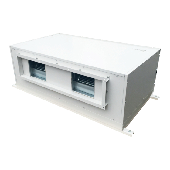
- Page 1 HORIZONTAL MINI AHU HAHU-EC Cooke Industries - Phone: +64 9 579 2185 Email: sales@cookeindustries.co.nz Web: www.cookeindustries.co.nz...
- Page 2 INVESTING IN QUALITY, RELIABILITY & PERFORMANCE ISO 9001 QUALITY World Leading Design and Technology Every product is manufactured to Equipped with the latest air-conditioning test meet the stringent requirements of rooms and manufacturing technology, we the internationally recognized ISO produce over 50,000 fan coil units each year, all 9001 standard for quality assurance conforming to the highest international in design, development and...
-
Page 3: Table Of Contents
TABLE OF CONTENTS A. TECHNICAL DATA ................................4 A.1. G ..............................4 ENERAL ESCRIPTION A.2. G ..............................6 ENERAL PECIFICATIONS A.3. C ..................................10 A.4. S ................................. 11 OUND A.5. D ..............................16 IMENSIONAL RAWINGS B. INSTALLATION .................................. 18 B.1. S .............................. - Page 4 MODEL CODE NOMENCLATURE HAHU -200 Notation Description HAHU Horizontal Air Handling Unit 4R: 2-pipe 4 rows 6R: 2-pipe 6 rows 4R+2: 4-pipe with 4rows cooling and 2 rows heating Unit Size (See General Specification Section A for cooling and heating capacities.) V –...
-
Page 5: Technical Data
A. Technical Data A . 1. G e n e r a l D e s c r i p t i o n HAHU unit is an ideal air handling terminal unit for suspended ceiling installation and suitable for ducted air distribution. It is constructed of sandwich panels to achieve low noise level during operation. - Page 6 ACCESSORIES Optional accessories can be selected: G4 (Merv 8) ) or F8 (Merv 14) filter module, Mixing and recirculating chamber, 0~10V Modulating 2-way valve kit, On/Off valve kit, Electrical heating module, thermostat, AQI control PCB-S5, Complete function PCB-S6, Wired wall pad, Differential pressure transducer. Mixing &...
-
Page 7: General Specifications
A . 2. G e n e r a l S p e c i f i c a t i o n s Product range: HAHU-4R-V-EC 4-row coil 2-pipe with EC motor(s) HAHU-4R-[Size]-V-EC Configuration 2 pipes Unit Number of Fan Blowers configuration Power supply (V/Ph/Hz) 220~240/1/50 or 60... - Page 8 Product range: HAHU-6R-V-EC 6-row coil 2-pipe with EC motor(s) HAHU-6R-[Size]-V-EC Configuration 2 pipes Unit Number of Fan Blowers configuration Power supply (V/Ph/Hz) 220~240/1/50 or 60 2329 3238 4166 6475 8332 Air flow 1980 2752 3541 5504 7082 1398 1943 2500 3885 4999 External Static Pressure...
- Page 9 Product range: HAHU-4R+1-P-EC 4-row coil for cooling and 1-row coil for heating 4-pipe with EC motor(s) HAHU-4R+1-[Size]-P-EC Configuration 4 pipes Unit configuration Number of Fan Blowers Power supply (V/Ph/Hz) 220~240/1/50 or 60 2422 3304 4228 6608 8457 Air flow m3/hr 2058 2808 3594...
- Page 10 Product range: HAHU-4R+2-P-EC 4-row coil for cooling and 2-row coil for heating 4-pipe with EC motor(s) HAHU-4R+2-[Size]-P-EC Configuration 4 pipes Unit Number of Fan Blowers configuration Power supply (V/Ph/Hz) 220~240/1/50 or 60 2537 3387 4307 6774 8613 Air flow m3/hr 2156 2879 3661...
-
Page 11: Coil Data
A . 3. C o i l D a t a 2-Pipe Systems 4 rows coil Fin Length Fins per No. of Fin width No. of Tube Ø Model height (mm) Inch Rows (mm) Circuits (mm) (mm) HAHU-4R-200 HAHU-4R-300 1050 HAHU-4R-400 1250 15.88... -
Page 12: Sound Data
A . 4. S o u n d D a t a Model HAHU-200-EC Speed 800 RPM 900 RPM 1000 RPM 1100 RPM 1200 RPM 1300 RPM 1400 RPM 1500 RPM Sound Power dB(A) 53.6 57.3 64.4 68.7 71.3 70.7 70.5 71.3 20 Hz... - Page 13 Model HAHU-300-EC Speed 800 RPM 900 RPM 1000 RPM 1100 RPM 1200 RPM 1300 RPM 1350 RPM 1400 RPM Sound Power dB(A) 56.6 59.9 67.7 72.6 75.2 74.2 74.1 74.3 20 Hz 18.4 15.1 25.9 27.9 19.2 29.0 32.7 32.7 25 Hz 16.8 19.6...
- Page 14 Model HAHU-400-EC Speed 800 RPM 900 RPM 1000 RPM 1100 RPM 1200 RPM 1300 RPM 1350 RPM 1400 RPM Sound Power dB(A) 62.1 65.4 73.2 78.1 80.7 79.7 79.6 79.8 20 Hz 23.9 20.6 31.4 33.4 24.7 34.5 38.2 38.2 25 Hz 15.4 22.3...
- Page 15 Model HAHU-600-EC Speed 800 RPM 900 RPM 1000 RPM 1100 RPM 1200 RPM 1300 RPM 1350 RPM 1400 RPM Sound Power dB(A) 60.6 63.9 71.7 76.6 79.2 78.2 78.1 78.3 20 Hz 22.4 19.1 29.9 31.9 23.2 33.0 36.7 36.7 25 Hz 13.9 20.8...
- Page 16 Model HAHU-800-EC Speed 800RPM 900RPM 1000RPM 1100RPM 1200RPM 1300RPM 1350RPM 1400RPM Sound Power dB(A) 65.1 68.4 76.2 81.1 83.7 82.7 82.6 82.8 20 Hz 26.9 23.6 34.4 36.4 27.7 37.5 41.2 41.2 25 Hz 18.4 25.3 28.1 28.1 30.5 32.6 31.9 31.9 31.5 Hz...
-
Page 17: Dimensional Drawings
A . 5 . D i m e n s i o n a l D r a w i n g s 2 Pipe Model Water Connection HAHU-200 1080 1210 HAHU-300 1280 1410 HAHU-400 1480 1610 1-1/4” HAHU-600 1680 1810 HAHU-800 1980... - Page 18 4 Pipe Water Model Connection HAHU-200 1080 1210 HAHU-300 1280 1410 Cooling : 1- 1/4” HAHU-400 1480 1610 Heating : 1” HAHU-600 1680 1810 HAHU-800 1980 2110 All dimensions are in mm. PG2021 Global HAHU-VP-ECM-005 Cooke Industries - Phone: +64 9 579 2185 Email: sales@cookeindustries.co.nz Web: www.cookeindustries.co.nz...
-
Page 19: Installation
B . 1 . S a f e t y P r e c a u t i o n s • When installing, performing maintenance or servicing Polar Air fan coil units observe the precautions stated in this manual as well as those stated on the labels attached to the unit. -
Page 20: Location
B . 2 . L o c a t i o n Before installing and running the unit, please check the following: There must be enough space for unit installation and maintenance. Please refer to below figure for the unit's outlines and dimensions and for the minimum distance between the unit and the obstacle/ any obstructions/ its surroundings. -
Page 21: Installation Procedures
B . 3 . I n s t a l l a t i o n P r o c e d u r e s 1. The unit is designed to be installed in a concealed ceiling. Installation and maintenance should be performed by qualified personnel who are familiar with local codes and regulations, and are experienced with this type of appliance. -
Page 22: Insulation
CAUTIONS Dimension M and N are determined by air duct design. Air duct should be fire-proof. Please refer to concerned country national and local regulation. Circulatory air pressure drop should be approximately equal to the External Static Pressure. B . 4 . I n s u l a t i o n 1. -
Page 23: Unit Operation
B . 6 . U n i t O p e r a t i o n Confirm air has been properly bled from and there is waterflow through the coil. Confirm fan wheel is rotating and air is discharged at unit supply opening. Confirm power voltage between Terminals L1 and N. -
Page 24: Control Specifications: Intelligent Control (I Type)
D. Control Specifications: Intelligent Control (I Type) D . 1. I / O P o r t D e f i n i t i o n s f o r I t y p e Code 2-Pipe 4-Pipe Air Temperature Sensor Room air temperature sensor (Tr) Chilled water inlet sensor Water inlet temperature sensor... -
Page 25: Wiring Diagrams For Itype
D . 2 . W i r i n g D i a g r a ms f o r I t y p e Intelligent Control Wiring Diagram for HAHU-200~400-EC PG2021 Global HAHU-VP-ECM-005 Cooke Industries - Phone: +64 9 579 2185 Email: sales@cookeindustries.co.nz Web: www.cookeindustries.co.nz... - Page 26 Intelligent Control Wiring Diagram for HAHU–600 – 800 - EC PG2021 Global HAHU-VP-ECM-005 Cooke Industries - Phone: +64 9 579 2185 Email: sales@cookeindustries.co.nz Web: www.cookeindustries.co.nz...
-
Page 27: Control Logics Fori Control
D . 3. C o n t r o l L o g i c s f o r I C o n t r o l Control Logics for I Control For EC-S8 (300029=2) 2-pipe with modulating valve for EC-S8 (300046=0) COOL MODE 1) If Tr ≥... - Page 28 If 28ºC (300017 setting)<Ti1<28(3000017 setting)+4ºC, fan and DA2 are kept original state; If Ti1 ≥ 28(3000017 setting)+4ºC, fan runs at set speed. DA2 output is from minimum setting(300016setting) - 10Vdc based on Delta Ti and setting; if Ti sensor is damaged, Fan runs at set speed. MS300080=1, DA2 output is based on heating water flow reading and setting PID calculation.
- Page 29 activated, Indoor fan runs at set speed. EH is turned on. DA3 output is from minimum setting(300016setting) - 10Vdc based on Delta T3 /T4 and setting; b) If Tr > Ts+1 ºC then heat operation is terminated, Electrical heater is OFF. Indoor fan is turn OFF after 120S. c) The range of Ts is 16-30 ºC or fixed according to Parameter 4 setting.
- Page 30 speed. 3) The range of Ts is 16 - 30 ºC. 4) Indoor fan speed can be adjusted for low, medium, high and auto. LOW TEMPERATURE PROTECTION OF INDOOR COIL a) If Ti1 ≤ 2 ºC for 2 minutes, then MTV1 is turned off. DA2=0VDC. If indoor fan is set for low speed, then it will run at medium speed.
- Page 31 If unit is working at cool mode or Fan mode, if Ts-Tr>3.0ºC, MTV2 , MTV1 and DA2 are OFF more than 3 minutes, working mode will be changed to heating mode; 2-pipe with 6-way valve unit for EC-S8 (300046=2) COOL MODE 1) If Tr ≥...
- Page 32 c) The range of Ts is 16 - 30ºC. d) Indoor fan speed can be adjusted to low, medium, high and auto. DEHUMIDIFICATION MODE MTV1 is turned on; Ts=24ºC; If Tr ≥ 25ºC for 30S, DA2 is 1.5Vdc. Fan is running at auto speed. If 16ºC≤...
- Page 33 If the float switch (N/C) is opened before the unit is turned on and if running at COOL mode, then MTV1 is turned off. The drain pump will be turned on and indoor fan will keep running. After float switch is closed, MTV1 is turned on. If the unit is turned on in COOL mode and the float switch is opened continuously ≥...
-
Page 34: Open Modbus Protocol
D . 4. O p e n M o d b u s P r o t o c o l Open Modbus Protocol For EC-S8 Transfer Mode: RTU, BAUD Rate: 9600bps, 8 data bit, 1 stop bit, None parity bit The communications require a delay of 80ms between reading an answer and sending the next command. - Page 35 Holding Register table: Description Address Type* Remark Cooling mode = 01(H) Humidify mode = 02(H) Mode setting 300000 Fan mode = 04(H) Heating mode = 08(H) Auto mode = 10(H) Low speed = 04(H) Medium speed = 02(H) Fan speed setting 300001 High speed = 01(H) Auto fan speed = 07(H)
- Page 36 EH type 300047 0=without EH, 1=EH as booster; 2=EH as primary 0=Tr/Ts DA1 control signal mode 300048 1=ESP 0=CN4 working; EC motor input ports 300049 1=CN5 working 2=CN4+CN5 working default:0 0=NO; PRO1 input type 300050 1=NC 0=sensor on the wired wall pad; Tr sensor setting 300051 1=sensor on the main PCB;...
- Page 37 Input Register table: Description Address Type* Remark Tr temperature sensor 400000 Ti1 temperature sensor 400001 Ti2 temperature sensor 400002 Ti3 temperature sensor 400003 Ti4 temperature sensor 400004 Bit0 = Room temperature sensor error Bit1 = Ti1 temperature sensor error Bit2 = Ti2 temperature sensor error Bit3 = Float switch error Bit4 = Indoor coil low temperature protection Bit5 = Indoor coil over-heat protection...
-
Page 38: Modbus Network Setup For Fcu Group
D . 5. M o d b u s N e t w o r k S e t u p f o r F C U g r o u p Network Setup 1. Disconnect the communication plug from the control box 2. - Page 39 contact contact contact contact contact contact Check 1 and 2, 3 and 4, 5 and 6 to be sure connections are correct. 3.3.3. If the resistance between two wire contacts is too high, please check and reconnect the wire contacts. 3.3.4.
-
Page 40: Led Display And Error Description : I-Type ( Optional )
D . 6. L E D D i s p l a y a n d Er r o r D e s c r i p t i o n : I - Ty p e ( o p t i o n a l ) LED receiver in ABS housing with 0.5m or 1.8m pre-wiring Complete Function PCB –... -
Page 41: Control Specifications: Flexible Function (W Type)
E. Control Specifications: Flexible Function (W Type) E . 1 . I / O P o r t D e f i n i t i o n s f o r W t y p e I/O Port Definitions For W Code Phase Voltage input... -
Page 42: Wiring Diagrams For Wtype
E . 2 . W i r i n g D i a g r a m s f o r W t y p e Flexible Function PCB W4 for HAHU-200~400-EC PG2021 Global HAHU-VP-ECM-005 Cooke Industries - Phone: +64 9 579 2185 Email: sales@cookeindustries.co.nz Web: www.cookeindustries.co.nz... - Page 43 Flexible Function PCB: EC-W5 for HAHU-600~800-EC PG2021 Global HAHU-VP-ECM-005 Cooke Industries - Phone: +64 9 579 2185 Email: sales@cookeindustries.co.nz Web: www.cookeindustries.co.nz...
-
Page 44: Control Logic Specifications
E . 3 . C o n t r o l L o g i c S p e c i f i c a t i o n s Control Logic Specifications for W4/W5 The unit is turned ON when modulating signal input is more than 2.0VDC or Modbus 300006 and 300007 settings; The unit is turned OFF when modulating signal input is less than 2.0VDC and Modbus 300006 and 300007 settings. -
Page 45: User Interface
F. User Interface F . 1 . R e m o t e H a n d s e t f o r I - c o n t r o l Interchange F and C on Display Press up and down buttons for 3 seconds, then release. -
Page 46: Wired Wall Pad Controller For I-Control
F . 2 . W i r e d W a l l P a d C o n t r o l l e r f o r I - C o n t r o l LED display Code Legend Code... -
Page 47: Operation Guide
Operation guide On/OFF Press to turn on. Press it again to turn off. Button Mode button With wall pad on, press to select Cooling, Dehumidification, Heating, Ventilation or Auto sequentially.or Auto sequentially. Fan Speed Button Press S30 to change from 0 to3. 0=Auto speed, 1=Low speed, 2=Medium speed, 3=High speed. Parameter Setting Long press... - Page 48 1=Fahrenheit degree. S31/S32 displays “U003”, which is used to select display temperature on LCD. 1=Setting temperature. 0=Room temperature. S31/S32 displays “U004”, which is used to set setting temperature range. 0=Setting temperature is from 16~30°C. 1=Cooling setting temperature 24°C, Heating setting temperature 21°C. S31/S32 displays “U005”, which is used to set setting temperature band.
- Page 49 0=S34/S35/S36/S37 disappears 1=S34/S35/S36/S37 appears In cooling and dehumidification mode, cooling energy consumption is shown. In heating mode, heating energy consumption is shown. 2=Motor running time is shown. S31/S32 displays “U024”, which is used to set low speed RPM or control signal. S31/S32 displays “U025”, which is used to set medium speed RPM or control signal.
-
Page 50: Error Code List
Error Code List Error Description Code Reason Remedy 1. Check if Tr plug is connected or not. Room temperature sensor error Room sensor unplugged or damaged. 2. Check if sensor’s resistance is correct or not. 1. Check if Ti1 plug is connected or not. Indoor coil sensor 1 failure Ti1 sensor unplugged or damaged. -
Page 51: Dimensions And Installation
Dimensions and installation Dimensions Installation 1. Remove the screw on the bottom and remove the 2. Fix the back panel to wall and then connect the back connection panel. Display on the back panel. PG2021 Global HAHU-VP-ECM-005 Cooke Industries - Phone: +64 9 579 2185 Email: sales@cookeindustries.co.nz Web: www.cookeindustries.co.nz... -
Page 52: Sensor Resistance R-T Conversion Table
G. Sensor Resistance R-T Conversion Table Resistance: R (25°C) = 10KΩ ± 1% Beta Constant: B (25/85) = 3950 ± 1% Temp. Rmax Rnor Rmin Temp. Rmax Rnor Rmin (deg. C) (k Ohms) (k Ohms) (k Ohms) (deg. C) (k Ohms) (k Ohms) (k Ohms) 186.3613... -
Page 53: Troubleshooting
Temp. Rmax Rnor Rmin Temp. Rmax Rnor Rmin (deg. C) (k Ohms) (k Ohms) (k Ohms) (deg. C) (k Ohms) (k Ohms) (k Ohms) 5.4018 5.3146 5.2283 1.4137 1.3722 1.3317 5.1907 5.1049 5.0199 1.3681 1.3275 1.2880 4.9890 4.9045 4.8210 1.3243 1.2845 1.2458 4.7961... - Page 54 Cooke Industries - Phone: +64 9 579 2185 Email: sales@cookeindustries.co.nz Web: www.cookeindustries.co.nz...
Need help?
Do you have a question about the MINI AHU HAHU-EC and is the answer not in the manual?
Questions and answers