Table of Contents
Advertisement
Quick Links
Advertisement
Table of Contents

Subscribe to Our Youtube Channel
Related Manuals for Polar Air Coanda Series


Summary of Contents for Polar Air Coanda Series
- Page 1 SK2018 CHV2-V/P-ECM-001...
- Page 2 Page 1 of 67 INVESTING IN QUALITY, RELIABILITY & PERFORMANCE ISO 9001 QUALITY World Leading Design and Technology Every product is manufactured to Equipped with the latest air-conditioning test rooms meet the stringent requirements of and manufacturing technology, we produce over the internationally recognized ISO 50,000 fan coil units each year, all conforming to the 9001 standard for quality assurance in...
-
Page 3: Table Of Contents
Page 2 of 67 Table of Contents A. Technical Data ..................................5 A.1. General Description ............................... 5 A.2. General Specifications ..............................6 A.2.1. 2-Pipe Systems ................................ 6 A.2.2. 4-Pipe Systems ................................ 7 A.3. Coil Data ..................................8 A.4. Dimensional Drawings ..............................9 A.5. - Page 4 Page 3 of 67 D.4. Control Logic For 2-Pipe System ........................... 38 D.4.1. With Valve Configuration ............................38 D.4.2. Without Valve Configuration ..........................40 D.5. Control Logic For 4-Pipe System ........................... 41 D.6. Sleep Mode .................................. 43 D.7. Auto Fan Speed ................................43 D.8.
- Page 5 Page 4 of 67 Model Code Nomenclature CHV2 -ECM EC Motor Configuration Complete function on board PCB with integrated group control functionality. Flexible function on board PCB with drain pump and zone control functionality. Chilled/Hot Water, 4-Pipe Chilled/Hot Water, 2-Pipe Chilled Water, 2-Pipe with Electric Heater Unit Sizes.
-
Page 6: Technical Data
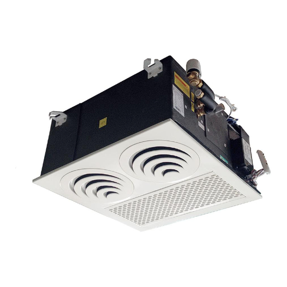
Page 5 of 67 Technical Data General Description CHV2 units generate an airflow with “Coanda” effect due to particular air handling section. The unit is suitable for installation in a suspended ceiling. Air intake is from the bottom while the air supply is parallel to the ceiling through practical and functional intake and outlet grilles. -
Page 7: General Specifications
Page 6 of 67 General Specifications 2-Pipe Systems Product range: CHV2 Coanda Effect Hydronic unit 2-pipe with EC motor CHV2-[Size]-V~-ECM Configuration 2-pipe Number Of Fan Blowers Single Twin Unit 230 / 1 / 50 Power Supply (V/Ph/Hz) Configuration 220 / 1 / 60 ~S: Complete function on board PCB with integrated group control functionality. -
Page 8: 4-Pipe Systems
Page 7 of 67 4-Pipe Systems Product range: CHV2 Coanda Effect Hydronic unit 4-pipe with EC motor and 1 row Auxiliary Heating Coil CHV2-[Size]-P~ECM Configuration 4-pipe Number Of Fan Blowers Single Twin Unit 230 / 1 / 50 Power Supply (V/Ph/Hz) Configuration 220 / 1 / 60... -
Page 9: Coil Data
Page 8 of 67 Coil Data 2-Pipe Systems Tube Fin Height Fins / No. of No. of Model Fin Length (mm.) Diameter (mm) inch rows circuits (inch) CHV2-01-V 3/8” CHV2-02-V 3/8” CHV2-03-V 1058 3/8” 4-Pipe Systems (1-row Auxiliary Heating Coil) Tube Fin Height Fins /... -
Page 10: Dimensional Drawings
Page 9 of 67 Dimensional Drawings 1195 SK2018 CHV2-V/P-ECM-001... -
Page 11: Sound Power Data
Page 10 of 67 Sound power data Model CHV-01-ECM Speed 600RPM 650RPM 700RPM 750RPM 800RPM 850RPM 900RPM 950RPM 1000RPM 1050RPM 1100RPM 1150RPM 1200RPM 1250RPM 1300RPM 1350RPM Sound Power 33.8 36.6 39.1 41.0 43.0 44.4 45.8 47.6 48.6 50.1 51.7 52.9 54.3 55.4 56.3... - Page 12 Page 11 of 67 Model CHV-02-ECM Speed 600RPM 650RPM 700RPM 750RPM 800RPM 850RPM 900RPM 950RPM 1000RPM 1050RPM 1100RPM 1150RPM 1200RPM 1250RPM 1300RPM 1350RPM Sound Power 37.0 39.1 41.6 43.1 45.1 46.7 48.4 49.7 50.9 52.2 54.1 54.9 56.0 56.9 58.1 59.2 dB(A) 20.0...
- Page 13 Page 12 of 67 Model CHV-03-ECM Speed 600RPM 650RPM 700RPM 750RPM 800RPM 850RPM 900RPM 950RPM 1000RPM 1050RPM 1100RPM 1150RPM 1200RPM 1250RPM 1300RPM 1350RPM Sound Power 38.5 40.9 42.9 45.0 46.8 48.8 50.4 51.5 53.4 54.8 56.2 57.7 59.0 59.8 60.5 61.5 dB(A) 20.0 10.1...
-
Page 14: Valve Information
Page 13 of 67 Valve Information 2-Way 1/2” Valve Body Valve Code Valve Dimensions (mm) (valve body + ON/ OFF thermoelectric actuator) 19.5 SGS14HFCA-23020101 (G1/2”) 3-Way 1/2” Valve Body Valve Code Valve Dimensions (mm) (valve body + ON/ OFF thermoelectric actuator) SGS14HFCA-23020102 (G1/2”) - Page 15 Page 14 of 67 Actuator Model DR-16-230B DR-16-24B DR-15B-24B Normal closed Normal closed Normal closed Voltage 230Vac 24Vac 24Vac Working force 90~125N 90~125N 90~125N Time 4.5min 4.5min 4.5min Power Full stroke 3.5mm 3.5mm 5.0mm SK2018 CHV2-V/P-ECM-001...
-
Page 16: Installation
Installation Safety Precautions • When installing, performing maintenance or servicing Polar Air fan coil units observe the precautions stated in this manual as well as those stated on the labels attached to the unit. • Ensure all local and national safety codes, laws, regulations, as well as general electrical and mechanical safety guidelines are followed for installation, maintenance and service. -
Page 17: Standard Configurations And Accessories
Page 16 of 67 Standard Configurations and Accessories First check the contents of the package. There are three types of plug-and-play control box: Plug-and-play control box – EC-S1 Control CHV2-(V/P) S1 configuration – complete function integrated controller, compatible with IR handset controller, wired wall-pad, serial networking for master-slave and MODBUS applications, and with optional Electric Heater compatibility. -
Page 18: Operating Limits
Page 17 of 67 Operating Limits Power supplies Volt Phase Water circuit Minimum entering water temperature +2 °C Maximum entering water temperature +80 °C Water side recommended maximum pressure 1600 kPa Before Installation The installation site must be established by the system designer or other qualified professional, taking account of the technical requisites and current standards and regulations. -
Page 19: Installation Location
Page 18 of 67 Installation Location Do not install the unit in rooms where flammable gas or alkaline acid substances are present. Aluminum/copper coils and/or internal plastic components can be damaged irreparably. Do not install in workshops or kitchens; drawn in oil vapors might deposit on the coils and alter their performance or damage the internal plastic parts of the unit. -
Page 20: Pipe Works
Page 19 of 67 Pipe Works Water connection The fan coils are designed for heating and cooling systems. 1. Fan 2. Heat exchanger 3. Air Vent / Water Purge 4. Joint 5. Valve CHV2 unit uses a 1/2” water piping connection with gaskets. It is advisable to tighten the connections with two spanners. -
Page 21: External Drain Pan Installation
Page 20 of 67 External Drain Pan Installation Align the two screw holes in the fixing plate to the two holes in the external drain pan. (Figure B.8.1) Make sure the drain pan is horizontal. Tighten the two screws while making sure the external drain pan is installed flush against the fixing plate. (Figure B.8.2) When the installation is completed, it is necessary to wrap the connecting pipe with thermal insulation to prevent condensation on ceiling tiles. -
Page 22: Valve Installation
Page 21 of 67 Valve Installation Review below table for information on valve diameter. External valve information Model Connector dia. Type (inch) CHV2-01/02/03 2-way & 3-way 1/2” See drawings of external valve installation below: Piping for 2-Pipe System 3-Way 4 Port Valve 1/2” Water Outlet 1/2”... -
Page 23: Fresh Air And Branch Duct Connection
Page 22 of 67 Fresh Air and Branch Duct Connection The fresh air system for CHV2 unit allows up to 15% of unit airflow. (Maximum air flow per connection is 100 There are two openings for connecting fresh air ducts and one opening for connecting a branch duct. ... - Page 24 Page 23 of 67 Connection Procedures: Look for the yellow stickers on the casing for locations of branch duct and fresh air intake connections. Each sticker is at the center of a knock out hole underneath the casing insulation. Use a cutter and follow along the pre-cut circular marking as shown and trim off the insulation.
-
Page 25: Suspension Bolts Layout And Ceiling Opening
Page 24 of 67 Suspension Bolts Layout and Ceiling Opening Using the installation template, open the ceiling panels and install the suspension bolts as in the images below. CHV2-01 580 x 587: Dimensions for Opening 606 x 450: Suspension Bolts CHV2-02 580 x 887: Dimensions for Opening 606 x 750: Suspension Bolts... - Page 26 Page 25 of 67 CHV2-03 580 x 1187: Dimensions for Opening 606 x 1050: Suspension Bolts (All dimensions shown in mm) Mark position of field supplied suspension rods, water lines, condensate drain pipe, line voltage and low voltage wiring. ...
-
Page 27: Suspension Installation
Page 26 of 67 Suspension Installation Lift unit (without front panel) with care by four corners only. Do not lift unit by the condensate drain discharge pipe or piping connections. Incline and insert the unit into the ceiling. Insert support rods into the bracket slot. Recommended clearance between the unit and false ceiling is 3mm. -
Page 28: Interconnecting Wiring
Page 27 of 67 Interconnecting Wiring It is recommended using screened cable in electrically noisy areas. Do not install fan coil unit in a location where electromagnetic waves may be directly emitted towards infra-red receiver on the unit. ... -
Page 29: Maintenance
Page 28 of 67 Maintenance Turn off the main power switch before performing any service or maintenance operations. Please see section B.1 Safety Precautions. The air filter is made of acrylic fiber and is washable in water. To remove filter simply open the intake grille by releasing the two fasteners. -
Page 30: Filter Removal And Cleaning
Page 29 of 67 Filter Removal and Cleaning Step 1: Unlock the two fixing screws on front panel. Step 2: Open the grille downward with care. Step 3: Pull the filter out along the slot. Step 4: Clean the filter and reassemble. Front panel fixing screws Control Box Replacement... -
Page 31: Condensate Drain Pump And Float Switch Replacement
Page 30 of 67 Condensate Drain Pump and Float Switch Replacement Step 1: Remove 4 screws from the side casing Screws Step 2: Pull out the condensate pump kit. Step 3: Replace it and tighten the 4 screws SK2018 CHV2-V/P-ECM-001... -
Page 32: Fan Deck Or Coil Assembly Replacement
Page 31 of 67 Fan Deck or Coil Assembly Replacement Step 1: Open the return air grille and remove the front panel by two fixing screws Front panel fixing screws Step 2: Pull out the Fan Deck Step 3: Remove the internal drain pan and coil assembly Step 4: Replace new fan deck or coil assembly SK2018 CHV2-V/P-ECM-001... -
Page 33: Motor And Fan Blower Replacement
Page 32 of 67 Motor and Fan Blower Replacement Step 1: Repeat Step 1 to 3 from Section C.7. Step 2: Use a spanner to remove the fan blower. Step 3: Remove the motor by undoing the 4 bolts. Step 4: Disconnect motor wire connector and replace motor or fan blower. -
Page 34: Control Specifications: Complete Function Pcb - S Type Control
Page 33 of 67 Control Specifications: Complete Function PCB – S Type Control Abbreviations Ts = Setting temperature AUX1 = Hot water free contact Tr = Room air temperature AUX2 = Chilled water free contact Ti1 = Chilled water coil temperature MTV1 = Chilled water valve Ti2 = Hot water coil temperature MTV2 = Hot water valve... -
Page 35: Wiring Diagram
Page 34 of 67 Wiring Diagram Standard EC-S1 Control PCB EC-S1-2018 EC-S1 Unit wiring scheme DIPA-S1 SW1-5: set the unit address SW6: set unit type :master or slave NEXT UNIT Mode Configuration SW7=0;SW8=0; unit operates in cooling/heating SW7=0;SW8=1; unit operates in cooling/heating w/booster FUSE SW7=1;SW8=0 ;... -
Page 36: Master Slave Networking Wiring Diagram
Page 35 of 67 Master Slave Networking Wiring Diagram: FLOAT EH2 EH1 PR2 PR1 FLOAT EH2 EH1 PR2 PR1 FLOAT EH2 EH1 PR2 PR1 LED display / IR receiver X-DISI LED display / IR receiver X-DISI LED display / IR receiver X-DISI A B A B A B A B... -
Page 37: Configuration Settings
Page 36 of 67 Configuration Settings DIPA-S1 DIPB-S2 SW1-SW5 Network address setting SW5/SW6 Fan Qty setting SW5=0 Single fan application SW6=1 SW5=1 Twin fan application Master / Slave setting SW6=1 SW6=1 Master SW6=0 Slave Preheat temperature setting SW4=1 28ºC SW4=0 36ºC SW7/SW8 Operating mode SW7=0 Cooling and heating modes available... - Page 38 Page 37 of 67 Fan Coil Unit ON/OFF There are 3 ways to turn the system on or off: a) By the ON/OFF button on the remote handset or wired wall pad; b) By the programmable timer on the handset or wired wall pad. c) By the manual control button on the air conditioner.
-
Page 39: Control Logic For 2-Pipe System
Page 38 of 67 Control Logic For 2-Pipe System With Valve Configuration COOL MODE a) MTV2, AUX1 and electric heater are always off. b) If Tr ≥ Ts + 1ºC (or + 4ºC if economy contact is activated), then cool operation is activated and MTV1 and AUX2 are turned on. - Page 40 Page 39 of 67 If the indoor coil temperature sensor is damaged, the protection mode will be overridden and the pre-heat and post-heat set times will be used instead. PRE-HEAT Pre-heat without Electric Heater a) If Ti1 < 36ºC [or < 28ºC is selected by DIPB-S2 position SW4], then MTV1 and AUX1 are turned on, indoor fan runs at Modbus 310000 setting.
-
Page 41: Without Valve Configuration
Page 40 of 67 b) MTV1 has stopped ≥ 10 min. Note: Auto cool or auto heat operation are the same as cool or heat mode respectively. Without Valve Configuration COOL MODE Electric heater, AUX1, MTV1 and MTV2 are always off. If Tr ≥... -
Page 42: Control Logic For 4-Pipe System
Page 41 of 67 At the end of the above dehumidification cycle, the system will decide the next dehumidification control option. Indoor fan will run at low speed throughout the dehumidification process. AUTOMODE Not available. Control Logic For 4-Pipe System Note: 4-pipe system must always be equipped with 2 valves. - Page 43 Page 42 of 67 PRE-HEAT Without Electric Heater a) If Ti2 < 36ºC [or 28ºC depends on DIP setting], then MTV2 and AUX1 are on, then indoor fan remains off. b) If Ti2 ≥ 38ºC [or 30ºC depends on DIP setting], then MTV2 and AUX1 are on, then indoor fan runs at set speed. If indoor coil temperature sensor is damaged, then pre-heat time is set for 2 minutes and indoor fan runs at set speed.
-
Page 44: Sleep Mode
Page 43 of 67 Sleep Mode a) The sleep mode can only be set when the unit is in cool mode or heat mode. b) If the sleep mode is activated when the unit is in cool mode, then the indoor fan will run at low speed and Ts will increase by 2ºC over 2 hours. -
Page 45: Buzzer
Page 44 of 67 Buzzer If a command is received by the fan coil unit, the master unit will respond with 2 beeps for each setting, and the slave unit will respond with 1 beep. Auto Restart The system uses non-volatile memory to save the present operation parameters when system is turned off or in case of system failure or cessation of power supply. -
Page 46: Low Temperature Protection Of Indoor Coil In Winter
Page 45 of 67 Low Temperature Protection of Indoor Coil in Winter This is frost protection for when the unit is off to prevent water in the coil and room from freezing. If Unit with SW2=0 (2-pipe system), is in Standby Mode If Tr ≦... -
Page 47: Led Display And Error Description
Page 46 of 67 LED Display and Error Description LED receiver in ABS housing with 0.5m (SGS14HFCA-01010101) or 1.8m (SGS14HFCA-01010102) pre-wiring Complete Function PCB - S Control Type Fan speed setting LED indication Condition High speed Red LED On Normal Medial speed Yellow LED On Normal... -
Page 48: Led Display On Master/Slave Connection
Page 47 of 67 LED Display on Master/Slave connection The error message indicating the defect status of all slave units will be shown in LED lights on the master unit. Master unit LED Unit No. Blink Remedy Unit 2 failure RED LED blinks 2 times, stops for 3s Check unit 2 communication plug and fix it Unit 3 failure... -
Page 49: Networking System
Page 48 of 67 Networking System Master-Slave Network The control PCB can be set either as a master unit or slave unit. Mater Unit Function a) The master unit sends data regarding its setting to the slave unit. b) The master unit settings are unit ON/OFF, Mode, Fan Speed, Timer, Clock, Set Temperature, and Sleep Function for handset operation. -
Page 50: Master-Slave Network Setup
Page 49 of 67 Master-Slave Network Setup 1) Disconnect the communication plug from the control box Communication plug A, B, A, B is printed on the main PCB. When you connect the wires, please ensure connection of A to A and B to B Connection wire If the total length of wire is more than 1000m, please use shielded wire in order to protect the signal transmission. - Page 51 Page 50 of 67 First unit Middle unit Last unit Wire connection check a) After the wire connection is completed, please check that the wire colours correspond. b) Check the wire contact by using a multimeter. contact contact contact contact contact contact c) Check 1 and 2, 3 and 4, 5 and 6 to be sure the connections are correct.
-
Page 52: Master-Slave Communication Method
Page 51 of 67 Master-Slave Communication Method There are two modes for the master-slave structure. Global Control communication The master unit will broadcast the settings to all slave units. During normal operation, slave units can receive commands from its wireless handset and wall pad control panel. Upon receiving the master global commands, all slave unit settings will be replaced by the master settings. -
Page 53: Open Modbus Protocol
Page 52 of 67 Open Modbus protocol Transfer Mode: RTU, BAUD Rate: 9600bps, 8 data bit, 1 stop bit, None parity bit The communications require a delay of 80ms between reading an answer and sending the next command. All temperatures are equal to reading data*10 accuracy: 0.1 degree C Supported Functions: Function Code... - Page 54 Page 53 of 67 Holding Register table: Description Address Type* Remark Cooling mode = 01(H) Humidify mode = 02(H) Mode setting 300000 Fan mode = 04(H) Heating mode = 08(H) Auto mode = 10(H) Low speed = 04(H) Medium speed = 02(H) Fan speed setting 300001 High speed = 01(H)
- Page 55 Page 54 of 67 Input Register table: Description Address Type* Remark Dip switch 1 status 400000 Dip switch 2 status 400001 Room temperature sensor 400002 Ti1 temperature sensor 400003 Ti2 temperature sensor 400004 Bit0 = Room temperature sensor error Bit1 = Ti1 temperature sensor error Bit2 = Ti2 temperature sensor error Bit3 = Float switch error Bit4 = Indoor coil low temperature protection...
-
Page 56: Control Specifications: Flexible Function Pcb - W-Type Control
Page 55 of 67 Control Specifications: Flexible Function PCB – W-Type Control Used in all CHV2 [V/P] W unit configurations. SK-NCGH-002-ECM is for CHV2 without Electric Heater. SK-NCGH-003-ECM is for CHV2 with Electric Heater. Features a. Condensate management with valve protection and NC alarm contact. b. -
Page 57: Wiring Diagrams
Page 56 of 67 Wiring Diagrams Standard Unit Wiring Diagram: Flexible Control PCB – EC-W1-Type Control EC-W1 unit wiring scheme EC-W1-2018 0~10Vdc from thermostat ALARM FUSE1 Main power supply EH L M H AUTO COM PROG1 230Vac 50Hz EMI1 RLY2 2 pipe sensor (Ti1) EH 2.5mm2 Cooling valve signal (230Vac) - Page 58 Page 57 of 67 EC-W1 unit with 2-modulating valves and ECM running at setting speed 0~10Vdc from thermostat AC/EC-S4 Thermostat Wiring scheme ALARM FUSE1 Main power supply EH L M H AUTO COM Legend: PROG1 230Vac 50Hz L1: Hi,M,L, V1, V2 power supply; High speed contact;...
-
Page 59: Control Logic Specifications
Page 58 of 67 Control Logic Specifications Unit Power ON/OFF a) The unit is turned ON when any of the fan speed inputs (from thermostat) are ON, or modulating signal input is more than 2.0 VDC. b) The unit is turned OFF only if all of the fan speed inputs (from thermostat) are OFF, or modulating signal input is less than 2.0 VDC. -
Page 60: Led Display And Error Description
Page 59 of 67 LED Display and Error Description LED receiver in ABS housing with 0.5m (SGS14HFCA-01010101) or 1.8m (SGS14HFCA-01010102) pre-wiring. Flexible Control PCB - W Control Type Fan speed setting LED indication Condition High speed Red LED On Normal Medium speed Yellow LED On Normal... -
Page 61: User Interface
Page 60 of 67 User Interface Remote Handset Interchange F and C on Display Press up and down buttons for 3 seconds, then release. Louver It is not available. Swing It is not available. Attention When unit with handset is the master unit, its settings are automatically sent to the slave units;... -
Page 62: Wired Wall Pad Controller
Page 61 of 67 Wired Wall Pad Controller Real Time display Day display Timer display Mode display Temperature display Fan speed display Master-Slave Button display Network icon Sleep icon Key lock SK2018 CHV2-V/P-ECM-001... - Page 63 Page 62 of 67 Buttons function Button Name ONOFF MODE DOWN Function Switch on or Switch between Change Fan Switch Modify Modify off the unit modes Speed interfaces parameters parameters Press to change function setting: (CNT stands for pressing times) (1)...
- Page 64 Page 63 of 67 When DIP SW2=OFF, room temperature is shown on temperature display area. Mode setting Press to set COOL, HEAT, FAN or DRY mode alternatively. Key Lock Press to set key lock function. Key lock icon is on or off when key lock function is set to on or off. Fan speed setting Press to set LOW, MEDIUM, HIGH or AUTO speed.
- Page 65 Page 64 of 67 13. Parameter checking Press six times to enter parameter checking interface. Local unit parameter is shown in temperature display area. Unit number is shown in real time hour area and parameter number is shown in real time minute area. For example, 2:03 stands for No.2 unit and No.3 parameter.
-
Page 66: Sensor Resistance R-T Conversion Table
Page 65 of 67 Sensor Resistance R-T Conversion Table Resistance: R (25°C) = 10KΩ ± 1% Beta Constant: B (25/85) = 3977 ± 1% Rmin Rnom Rmax Rmin Rnom Rmax (KΩ) (KΩ) (KΩ) (KΩ) (KΩ) (KΩ) °C °C 182.7 191.8 26.11 26.9 27.71... - Page 67 Page 66 of 67 Resistance: R (25°C) = 10KΩ ± 1% Beta Constant: B (25/85) = 3977 ± 1% Rmin Rnom Rmax Rmin Rnom Rmax (KΩ) (KΩ) (KΩ) (KΩ) (KΩ) (KΩ) °C °C 5.614 5.759 5.907 1.417 1.474 1.532 5.387 5.53 5.673 1.37...
-
Page 68: Troubleshooting
Page 67 of 67 Troubleshooting Symptoms Cause Remedy The fan coil does not - Check for presence of voltage No voltage start up - Check fuse on board Mains switch in the “OFF position - Place in the “ON” position Faulty room control - Check the room control - Check fan motor... - Page 69 Page 68 of 67 SK2018 CHV2-V/P-ECM-001...
Need help?
Do you have a question about the Coanda Series and is the answer not in the manual?
Questions and answers