Table of Contents

Related Manuals for Doepke Dupline DSS 4R


Summary of Contents for Doepke Dupline DSS 4R
- Page 1 Doepke Dupline Tastsignalsensoren DSS 4R/DSS 4R-EIB mit Rückmeldung DSS 4R/DSS 4R-EIB Operating Signal Sensors with Acknowledgement Feature Bedienungsanleitung Operating Instructions 3931176/08/12/D...
-
Page 2: Table Of Contents
Doepke Inhaltsverzeichnis 1. Allgemeines ......................3 2. Kodierung......................3 3. Inbetriebnahme....................4 3.1. Allgemein ..................... 4 3.2. Anschluss von Tastschaltern an den DSS 4R ..........4 3.3. Anschluss von Tastschaltern an den DSS 4R-EIB ........5 4. Garantie ........................ 5 5. -
Page 3: Allgemeines
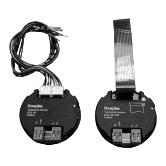
Doepke 1Inhaltsverzeichnis Bedienungsanleitung Tastsignalsensoren DSS 4R/DSS 4R-EIB 1. Allgemeines Die Tastsignalsensoren DSS 4R und DSS 4R-EIB sind Komponenten des Dupline In- stallationssystems und ermöglichen die Einbindung von Standard- und EIB-Tastern mit Rückmeldung. Sie verfügen über 4 Eingangskanäle und 2 Rückmeldekanäle mit der zusätzlichen Möglichkeit, den Buszustand anzuzeigen (BUS-OK-LED). -
Page 4: Inbetriebnahme
Doepke 3. Inbetriebnahme 3.1. Allgemein Die Installation darf nur von einer autorisierten Fachkraft vorgenommen werden. Bei der Installation ist das Anschlussschema zu beachten. Alle anzuschließenden Leitun- gen müssen spannungsfrei sein. Sowohl das Dupline-Signal als auch die 24 VDC-Spannungsversorgung sind bei beiden Tastsignalsensoren separat anzuschließen. -
Page 5: Anschluss Von Tastschaltern An Den Dss 4R-Eib
Doepke 3.3. Anschluss von Tastschaltern an den DSS 4R-EIB Die Verbindung zwischen dem DSS 4R und einem 2-fach EIB-Taster erfolgt über die 10-adrige, beigelegte flexible Leiterplatte mit Systemsteckern und der beigelegten Mon- tageplatte. Legen Sie dazu den DSS 4R mit angeschlossener Dupline-Leitung, Span- nungsversorgung und Systemkabel in die UP-Dose, führen Sie das Systemkabel wie... - Page 6 Doepke Min. Typ. Max. Kontaktbelastung 1 mA Erlaubter 1 kOhm Kontaktinnenwiderstand Leitungslänge Ausgänge (Rückmeldung) Art Transistor-Halbleiterausgänge, 24 VDC open collector Belastbarkeit / Ausgang 2 W (80 mA) Betriebsspannung Nennbetriebsspannung 21,5 VDC 24 VDC 26,5 VDC Eigenstromaufnahme 9,8 mA Anschlüsse DSS 4R...
-
Page 7: General Information
Doepke 1Table of Contents Operating Instructions DSS 4R/DSS 4R-EIB Operating Signal Sensors 6. General Information The DSS 4R and DSS 4R-EIB operating signal sensors are components of the Dupline installation system and enable conventional and EIB push-buttons to be linked to the system. -
Page 8: Putting Into Service
Doepke 8. Putting into Service 8.1. General Information Installation may only be carried out by an authorized, trained technician. Observe the connection diagram when installing. All lines to be connected must be dead. On both operating signal sensors the Dupline signal as well as the 24 VDC supply volt- age should connected separately. -
Page 9: Connection Of Eib Push-Buttons To Dss 4R-Eib
Doepke 8.3. Connection of EIB Push-buttons to DSS 4R-EIB The connection between the DSS 4R and a 2-way EIB operating switch is via the 10- pole flexible circuit-board supplied complete with system plug connectors and the mounting plate provided. To connect, insert the DSS 4R with connected Dupline line, power supply and system cable into the flush-mounted socket, pass the system cable through the mounting plate as illustrated below and connect the EIB switch. - Page 10 Doepke Min. Typ. Max. Contact load 1 mA Permissible inh. contact 1 kOhm resistance Length of line Outputs (Acknowledgement) Type Semiconductor outputs, 24 VDC open collector Load capacity / output 2 W (80 mA) Operating Voltage Rated operating voltage 21.5 VDC 24 VDC 26.5 VDC...
-
Page 11: Anschlussschema / Connection Diagram
Doepke 11. Anschlussschema / Connection Diagram 11.1. DSS 4R 3931176/08/12/D - The right to make technical changes reserved! -
Page 12: Dss 4R-Eib
Doepke 11.2. DSS 4R-EIB 3931176/08/12/D - The right to make technical changes reserved!
Need help?
Do you have a question about the Dupline DSS 4R and is the answer not in the manual?
Questions and answers