Table of Contents
Advertisement
Quick Links
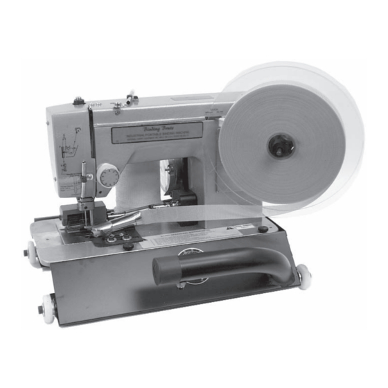
#155 DOUBLE PULL
BINDING BRUTE
INSTRUCTION MANUAL
Read Manual Before Operating Machine
9250 X
YLON
800-245-0267 • 763-315-5300 • F
W
S
: www.nationalequipment.com • E-M
EB
ITE
National
Flooring Equipment, Inc.
A
• M
VENUE
INNEAPOLIS
763-535-8255 • F
AX
, MN 55445 • U.S.A.
800-648-7124
AX
: info@nationalequipment.com
AIL
Advertisement
Table of Contents

Related Manuals for National 155

Summary of Contents for National 155
- Page 1 #155 DOUBLE PULL BINDING BRUTE INSTRUCTION MANUAL Read Manual Before Operating Machine National Flooring Equipment, Inc. 9250 X • M , MN 55445 • U.S.A. YLON VENUE INNEAPOLIS 800-245-0267 • 763-315-5300 • F 763-535-8255 • F 800-648-7124 : www.nationalequipment.com • E-M...
-
Page 2: Table Of Contents
TABLE OF CONTENTS Table of Contents ......................2 Rules for Safe Operation..................3-6 A. Grounding ......................5 B. Extension Cords ....................6 Introduction ........................7 Threading Instructions....................8-10 Thread Tension ....................11-12 Stitching ........................13 Folders ........................14-15 Maintenance ......................16 A. Lubrication......................16 B. Shuttle Area ......................16 C. Entire Machine ....................16 D. -
Page 3: Rules For Safe Operation
USE” until repaired. A guard or other damaged parts should be properly repaired or replaced. For all repairs, insist on only identical National replacement parts. 11. REMOVE ALL ADJUSTING KEYS AND WRENCHES: Make a habit of checking that the adjusting keys, wrenches, etc. - Page 4 20. STORE IDLE EQUIPMENT: When not in use, store in a dry, secured place. Keep away from children. 21. MAINTAIN LABELS AND NAMEPLATES: These carry important information. If unreadable or missing, contact National for a free replacement. 22. MACHINE IS HEAVY, DO NOT DROP. Page 4...
-
Page 5: Grounding
RULES FOR SAFE OPERATION GROUNDING WARNING: Improperly connecting the grounding wire can result in the risk of electric shock. Check with a qualified electrician if you are in doubt as to whether the outlet is properly grounded. Do not modify the plug provided with the tool. Never remove the grounding prong from the plug. Do not use the tool if the cord or plug is damaged. -
Page 6: Extension Cords
RULES FOR SAFE OPERATION EXTENSION CORDS WARNING Electrical cords can be hazardous. Misuse can result in fire or death by electrical shock. Read carefully and follow all directions. Grounded tools require a three wire extension cord. Double insulated tools can use either a two or three wire extension cord. -
Page 7: Introduction
INTRODUCTION As with our many other products offered to the carpeting industry we stand ready to warrant and assist you in any way possible. Should it be necessary for you to require service or assistance, please contact our sales or service representative at 800-245-0267. With the maintenance portion of the Video tape and this manual, it is our objective to provide you with both pictorial and written information necessary to assist you in proper servicing and maintenance of your Binding Brute. -
Page 8: Threading Instructions
THREADING INSTRUCTIONS 1. Raise needle to highest point. 2. Raise the feed roller. 3. Thread by following the letters indicated in the illustration (See Figure 1). A. Upper Thread Guide B. Enter Tension Discs C. Exit Tension Discs D. Take up Spring E. - Page 9 THREADING INSTRUCTIONS 1. Removal of Bobbin Case a. Raise feed roller. b. Rotate handwheel toward you until needle reaches its highest point. c. Tilt machine to rest on handwheel end. If you have binding wheels installed, use a small block box to support machine on handwheel.
- Page 10 THREADING INSTRUCTIONS 4. Needle Replacement a. To remove, rotate the handwheel towards you until it reaches its highest point. Using a 5/64 allen wrench, (provided in the kit), loosen the set screw above the needle and remove needle. b. To replace, grasp the needle with tweezers, and as viewed from the feed side of the machine, position needle with the long groove facing left and the notch side facing right.
-
Page 11: Thread Tension
THREAD TENSION 1. Proper thread tensions are important to obtain the optimum stitch appearance, proper knot location and tensions within the fabrics being sewn. *Indications of proper and improper thread tensions. When the upper and lower thread tensions are correct, the threads are knotted in the fabric center as in this illustration. - Page 12 THREAD TENSION 1. Installation and Threading of Binding Tape: Included with your machine are: • Large Black Plastic Discs (2) • Tape Reel Centering Plug • Binding Tape (1 Roll) Mount the tape reel: • Place the inner disc on spindle with smooth side to face tape reel. •...
-
Page 13: Stitching
STITCHING While sewing, NEVER pull on carpet or machine. This can cause needle deflection which can result in needle breakage and/or damage to the bobbin/shuttle mechanism. TO CHANGE DIRECTION OF STITCHING: • Stop sewing and if necessary, rotate hand wheel towards you until needle is in carpet. •... -
Page 14: Folders
For cotton binding, NATIONAL can supply a 3/4" folder model. It is recommended that you supply NATIONAL with a sample roll of the cotton binding for testing, and to specify the carpet type you intend to bind. Other folder types available are as follows: 3/4", 7/8", 1¼", 2", 2¼", 3", etc. - Page 15 FOLDERS As shipped, the folder is positioned to correctly bind in the full zig-zag mode. Straight stitching will require moving the folder to the left. Adjustment instructions per Figure 2 follows. 1. The slot in the folder bracket allows it to be moved left or right when changing between zig zag and straight on the stitch control.
-
Page 16: Maintenance
MAINTENANCE LUBRICATION Thorough and regular lubrication of your machine is essential to proper operation and long service. SHUTTLE AREA LUBRICATION Inspect and, if necessary, clean each time you change bobbins or after a maximum of one hour of continuous running. Lubricate after cleaning with the type of lubricant supplied with machine. Remove lower feed roller plate, bobbin case, hook retainer and hook. -
Page 17: Adjustments
ADJUSTMENTS TO CHECK NEEDLE HEIGHT ADJUSTMENT Needle as Viewed from Front Note: All screw locations marked in red are permanent and should not be adjusted. This adjustment should be checked if machine skips stitches, after machine jams, or a needle has broken. Install new needle incorrectly with the scarf to the outside (left) rather than inside (right), (See Figure 1). -
Page 18: Adjust Needle
ADJUSTMENTS TO ADJUST NEEDLE 1. Loosen set screw located in needle bar drive collar (part# 126-164, See Figure 1). 2. Slide needle bar (part #126-172) slightly up or down. 3. Tighten set screw in drive collar. 4. Recheck adjustment using procedure on Page 17. 3/32 Allen Set Screw Located in Drive Collar Shaft... -
Page 19: Needle To Hook Clearance
NEEDLE TO HOOK CLEARANCE 1. Remove: Lower feed roller plate (Model 126) or shuttle access plate (Model 155), pan, bobbin, and race cover. 2. Clean the shuttle area, hook and race cover prior to adjusting. TO CHECK: Figure 1 Install new needle backwards with the scarf to the outside (left) rather than inside (right) (See Figure 4). -
Page 20: Race Cover Spring Clearance
ADJUSTMENTS RACE COVER SPRING CLEARANCE ADJUSTMENT Remove the hook and install the race cover part# 126-140B. Handwheel the machine. The needle should be centered in the race cover ellipse (notch). Fig. 1. If not centered, loosen Screw ‘A’ and rotate shuttle. Proper adjustment will result in the needle passing through the race cover spring as shown in Fig. -
Page 21: Troubleshooting
TROUBLESHOOTING PROBLEM POSSIBLE CAUSE CORRECTIVE ACTION Skipping Bad needle ......... .Check needle Dirty shuttle area . -
Page 22: Binding Tips
Feed roller pressure may be reduced to make turning the machine easier. When operating with less pressure, use care not to force the machine and deflect or break the needle. Feed roller height is changed by loosening the set screw in the lift dog (part #178 Model 126, #778 Model 155). BASE BINDING If base starts to curl when binding, it is usually caused by tension on the binding tape. -
Page 23: Folder Adjustment
FOLDER ADJUSTMENTS For uneven folds where the bottom stitch misses the tape there are 2 possible solutions. 1. Place a straight edge in the front of the folder. Adjust the folder guide (part #126-1521) so that it just touches the straight edge and is at a slight angle away from the edge at the front. Trial and error maybe necessary with slightly more movement to the left (See Figure 1). -
Page 24: Binding And Stitching Instructions
BINDING & STITCHING INSTRUCTIONS NORMAL OUTSIDE CORNER Sew over end, then trim flush with edge Leave approximately 2-3'' strip each time. Sew over trimmed end. Repeat on each corner. When completed, fold and glue each corner strip. Page 24... - Page 25 BINDING & STITCHING INSTRUCTIONS OPTIONAL – DOUBLE COVERED CORNERS Sew over end leaving a 2'' to 3'' strip. Fold strip under. Leave a 2'' to 3'' strip at the end. Raise needle and cut. Place folded strip in folder. Sew down When completed fold and glue all the that side.
- Page 26 BINDING & STITCHING INSTRUCTIONS SEWN CORNERS It is possible, but more difficult to sew around corners. Corners done in this manner are usually not as sharp as those done by folding over and gluing. You have to raise the feed roller, watch the needle, and move the carpet only when the needle is up.
- Page 27 BINDING & STITCHING INSTRUCTIONS INSIDE CORNERS continued Fold back at cut and sew over end. Fold back sewed side. Start at cut. Push fibers into cut. Flatten tape from Top of completed corner. both sides and glue over cut. Page 27...
- Page 28 BINDING & STITCHING INSTRUCTIONS B. SECOND WAY Handsew the corners. Allow enough binding to reach corner Slide carpet in from back of machine and continue sewing Hand stitch corner when done Sew as close to corner as machine will allow and stop Rug Corner Page 28...
-
Page 29: Complete Parts List
COMPLETE PARTS LIST COMPLETE PARTS LIST PART # DESCRIPTION 126-C4T THREAD STAND BOLT & NUT 126-CS TAPE CENTERING PLUG FOR 7/8" TAPE 126-DISC BINDING DISC SET (INCLUDES DISC 1, DISC 2 & DISC COLLAR THUMB SCREW) 126-DISC1 REAR DISC 126-DISC2 FRONT DISC 126-DISC2A DISC COLLAR... - Page 30 COMPLETE PARTS LIST COMPLETE PARTS LIST (continued) PART # DESCRIPTION 126-123 DRIVE FORK RETAINER (2) 126-124S SHUTTLE DRIVE FORK, BEARING & BOLT ASSY. 126-125 CONNECTING ROD LOWER SPINDLE 126-126 CONNECTING ROD LOWER SPINDLE NUT 126-127 SHUTTLE OSCILLATOR CRANK SCREW ONLY (2) (NOT SHOWN) 126-128 SHUTTLE OSCILLATOR CRANK W/ SCREWS 126-130...
- Page 31 O-RING FOR LINK PIN 126-1302 E-CLIP FOR LINK PIN 126-1303 WASHER FOR LINK PIN (2) 126-1910A DRIVE MOTOR 110V BRUSHES (2) 126-1910B DRIVE MOTOR 230V BRUSHES (NOT SHOWN) 155-526 PAN ASSEMBLY 155-526-1 PAN (ONLY) 155-527 PAN THUMB SCREW (3) 155-528 SWITCH WASHER 155-530...
- Page 32 COMPLETE PARTS LIST COMPLETE PARTS LIST (continued) PART # DESCRIPTION 155-5260 220 V PAN ASSEMBLY 155-5290 220 V SWITCH ASSEMBLY 155-5340 220 V SPEED CONTROL 500-12 PAN POWER CORD 71021 1/8″ ID BEARING (6) 71081 5/8″ ID BEARING (2) 72301...
-
Page 33: Part Numbers And Diagrams
PART NUMBERS AND DIAGRAMS #126-03-3 ZIG ZAG LEVER BEHIND BINDING TAPE DISKS Solid Case 126-24-2 BOBBIN CASE This machine uses bobbin case with an eyelet: Part #126-112-1. Thread must pass through eyelet in bobbin case for proper operation. Tension on the bobbin thread should be light. You have a #23 needle in machine, when ordering needle ask for size #23, Part #126-B (126-B2A [10 pk], 126-B2 [100 pk]) Page 33... - Page 34 PART NUMBERS AND DIAGRAMS 74518 03HB 03HB 74510 24-2 03HN 03HN 74437 03HW 74567 74550 03-3 73002 74414 74414 19-1 74433 74433 Disc 1 Disc 2A 15 16 17 Disc 2B Disc 2 126-Disc PART # DESCRIPTION PART # DESCRIPTION 126-01 Frame 126-600...
- Page 35 PART NUMBERS AND DIAGRAMS 155-526 500-12 126-54 126-53 155-527 74406 126-52 73041 73353 155-537 126-57 80101 155-528 126-502A 155-533 155-530 72460 PART # DESCRIPTION PART # DESCRIPTION 155-537 Pan Wheel w/ Bearing (4) 126-52 Motor Power Recepticle 155-5260 220 V Pan Assembly...
- Page 36 PART NUMBERS AND DIAGRAMS 72301 126-198 126-199 126-194 126-194 73002 73002 126-196 126-192 126-1910A 73009 73009 PART # DESCRIPTION PART # DESCRIPTION 126-192 Drive Motor Pulley (Incl. set screw) 126-1910B Drive Motor 230V Brushes (Not Shown) 126-194 1/4-20 x 3/8 Drive Motor Lower 73002 1/4 Split Lock Washer (2) Mount Screw (2)
- Page 37 PART NUMBERS AND DIAGRAMS 74440 126-98 74414 126-92 73085 73007 155-568A 71081 71081 126-97 126-100 73346 126-96 126-104 155-573 155-572 74425 126-90 155-570 74414 71021 74405 70021 155-578 155-577-2 155-570-1 155-577-1 155-569 155-577 155-572 155-573 155-575 PART # DESCRIPTION PART #...
- Page 38 PART NUMBERS AND DIAGRAMS 155-636 536A 74437 544A PART # DESCRIPTION PART # DESCRIPTION 126-545 Stitch Control Assembly Mounting 126-528 Link Pin w/ Retainer Clip Screw (3) 126-529 Hand Wheel 126-546 Shuttle Oscillator Control Link w/ Screw 126-530 Hand Wheel Retainer Washer...
- Page 39 PART NUMBERS AND DIAGRAMS 112-1 1171 1172 1171 1192 74409 1242 119T 140B 74409 1301 74409 1242 124S 1303 1302 1303 1302 74569 1201 PART # DESCRIPTION PART # DESCRIPTION 126-110 Bobbin Case Spring w/Screw 126-130 Shuttle Oscillator Link Pin (2) 126-112-1 Bobbin Case w/Eyelet 126-131...
- Page 40 PART NUMBERS AND DIAGRAMS 74408 73064 PART # DESCRIPTION PART # DESCRIPTION 126-172A Needle Bar Thread Guide (Not Shown) 126-144 Feed Roller Lift Shaft Retainer 126-173 Needle Set Screw (Not Shown) 126-145 Feed Roller Lift Shaft 126-177 Feed Roller Lift Shaft Bushing 126-147 Needle Bar Drive Counter Balance 126-178...
- Page 41 • Can be purchased separately or ® in combination #1394 Silicone Spray 3M • For the #126 & #155 Binding A silicone product in a 13.25 oz. spray can that lubricates, #1394 Brutes repels water, helps prevent rust and corrosion •...
-
Page 42: Binding Accessories
#126-D2 1-1/4" clean top and bottom (Great for heavy Berber or thick unbeveled carpet) (Tucks top and bottom edges #126-G Fringe Attachment under. Folders are made for National binders; modifications may be required to fit other brand machines. Custom folders available; inquire. Page 42... -
Page 43: Guarantee
Due to our lack of control of the many conditions and techniques used in the field, National will not be held responsible for injury to anyone or damage to any object, resulting through the use of this product regardless of its age or condition or the manner in which it is used. -
Page 44: Return Sheet
Telephone Number Approximate Usage (hours) Problems Encountered Check One: Repair Do you wish to be contacted before repairing Return Contact National if a loaner is needed Return Authorization Number Date required, contact National Customer Number if known Purchased From if not directly from National...
Need help?
Do you have a question about the 155 and is the answer not in the manual?
Questions and answers