Advertisement
1. System Installation
Tire-Safeguard
system installation involves two steps:
1. Install the Receiver and Display in car.
2.
Install the Sensors on the wheels.
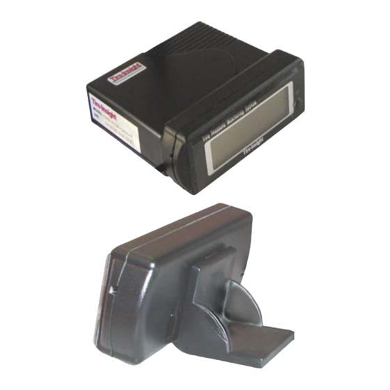
1.1 Parts List
1
Display Unit (TPM-DU)
2
Display Unit Support Clip (TPM-SC)
1
Display Unit Support Stand (TPM-SS)
1
Receiver Unit (TPM-RU)
4
Valve Mounted Sensor (TPM-V2)
1
Power Cord (TPM-PC)
3
2-Sided Adhesive Strip (TPM-AS)
1.2 Display Mounting Examples
Tire-Safeguard
Tire Pressure Monitoring System
TPM-V Model
Installation Manual
Display Mounting Example 1
Advertisement
Table of Contents

Related Manuals for HCI Tire-Safeguard TPM-V

Summary of Contents for HCI Tire-Safeguard TPM-V
- Page 1 Tire-Safeguard Tire Pressure Monitoring System TPM-V Model Installation Manual 1. System Installation Tire-Safeguard system installation involves two steps: 1. Install the Receiver and Display in car. Install the Sensors on the wheels. 1.1 Parts List Display Unit (TPM-DU) Display Unit Support Clip (TPM-SC) Display Unit Support Stand (TPM-SS) Receiver Unit (TPM-RU) Valve Mounted Sensor (TPM-V2)
- Page 2 Display Mounting Example 2 Display Mounting Example 3 Display Mounting Example 4 2.3, Receiver and Display Installation Display – Attach Support Clip or Stand to the Display and place the Display in the desired viewing location. Or attach Display to the receiver and secure with the 2-sided Adhesive Strip.
- Page 3 2.4 Sensor Installation Tire-Safeguard internal valve-mounted sensor has the following components. Each sensor has a label with an ID indicating the tire location. For first time installation always install sensor to its assigned location as showed in the following drawing. July 2006 TPM-V Installation Manual...
- Page 4 a) Elevate vehicle to a proper working height. b) Deflate the tires and remove the original valve stems. c) Match sensor number with the wheel location as showed below. Remove the sensor stem Cap (6). d) Adjust Body (2) to Stem (3) angle and then tighten Screw (1). Detach Sleeve (5) by inserting the Steel Pin (TPM-SP) to the hole on the Stem base and holding the Pin with one hand, and then using the other hand to twist the Sleeve counterclockwise - detaching it from the Stem.
Need help?
Do you have a question about the Tire-Safeguard TPM-V and is the answer not in the manual?
Questions and answers