Table of Contents
Advertisement
Quick Links
© Copyright 2015
EVERTZ MICROSYSTEMS LTD.
5292 John Lucas Drive
Burlington, Ontario
Canada L7L 5Z9
Phone:
+1 905-335-3700
Sales:
sales@evertz.com
Tech Support: service@evertz.com
Web Page:
http://www.evertz.com
Version 1.0, December 2015
The material contained in this manual consists of information that is the property of Evertz Microsystems and is intended solely for the use of
purchasers of the 7800EMR-IO product. Evertz Microsystems expressly prohibits the use of this guide for any purpose other than the operation of
the contained in this reference guide consists of information that is the property of Evertz Microsystems and is intended solely for the use of
purchasers of the 7800EMR-IO product. Due to on going research and development, features and specifications in this manual are subject to
change without notice.
All rights reserved. No part of this publication may be reproduced without the express written permission of Evertz Microsystems Ltd. Copies of
this manual can be ordered from your Evertz dealer or from Evertz Microsystems.
7800EMR-IO
32x32 AES & MADI Router/Interface
User manual
Fax: +1 905-335-3573
Fax: +1 905-335-7571
Advertisement
Table of Contents

Related Manuals for evertz 7800EMR-IO


Summary of Contents for evertz 7800EMR-IO
- Page 1 Version 1.0, December 2015 The material contained in this manual consists of information that is the property of Evertz Microsystems and is intended solely for the use of purchasers of the 7800EMR-IO product. Evertz Microsystems expressly prohibits the use of this guide for any purpose other than the operation of the contained in this reference guide consists of information that is the property of Evertz Microsystems and is intended solely for the use of purchasers of the 7800EMR-IO product.
- Page 2 This page left intentionally blank...
- Page 3 IMPORTANT SAFETY INSTRUCTIONS The lightning flash with arrowhead symbol within an equilateral triangle is intended to alert the user to the presence of uninsulated “Dangerous voltage” within the product’s enclosure that may be of sufficient magnitude to constitute a risk of electric shock to persons. The exclamation point within an equilateral triangle is intended to alert the user to the presence of important operating and maintenance (Servicing) instructions in the literature accompanying the product.
- Page 4 WARNING Changes or Modifications not expressly approved by Evertz Microsystems Ltd. could void the user’s authority to operate the equipment. Use of unshielded plugs or cables may cause radiation interference. Properly shielded interface cables...
-
Page 5: Table Of Contents
5.6. MADI STATUS TAB ......................20 5.7. TDM FAULTS TAB ......................21 5.8. MADI FAULTS TAB ......................21 5.9. MONITORING TAB FOR INDIVIDUAL CHANNELS OF 7800EMR-IO ....... 22 5.9.1. Audio TDM Processing Tab ..................23 5.9.2. Audio Mono Config Tab ................... 24 5.9.3. - Page 6 Figure 1-1: Standalone Mode Block Diagram ....................2 Figure 1-2: ADMX Mode Block Diagram ......................3 Figure 3-1: 7800EMR-IO Rear Plate ........................ 8 Figure 4-1: Illustration of the Front Card Edge of the 7800EMR-IO ..............9 Figure 4-2: Main Menu Prompt ........................10 Figure 5-1: VistaLINK - Adding the 7800EMR-IO’s as an Agent ..............
- Page 7 Evertz products are for informational use only and are not warranties of future performance, either expressed or implied. The only warranty offered by Evertz in relation to this product is the Evertz standard limited warranty, stated in the sales contract or order confirmation form.
- Page 8 7800EMR-IO 32x32 AES & MADI Router/Interface This page left intentionally blank Page - iv Revision 1.0...
-
Page 9: Overview
32x32 AES & MADI Router/Interface OVERVIEW The 7800EMR-IO is a compact modular audio router/interface that can be configured to operate in two different modes depending on the application requirements. The first mode is stand alone mode which the device will function as a standalone router with AES and MADI as input and output. The second mode is ADMX mode which will allow the module to act as an input and output interface and has to be connected to an ADMX crosspoint for integration into an EMR audio router. -
Page 10: Standalone Mode
7800EMR-IO 32x32 AES & MADI Router/Interface 1.1.1. STANDALONE MODE • 32 AES Inputs and 32 AES Outputs • 4 MADI Inputs and 4 MADI Outputs • 320 Mono or 160 Stereo Channels • Supports 4:1 Mono Mixing • Audio Monitoring for AES and MADI Signals •... -
Page 11: Admx Mode
7800EMR-IO 32x32 AES & MADI Router/Interface 1.1.2. ADMX MODE • 32 AES Inputs and 32 AES Outputs • 2 MADI Inputs and 2 MADI Outputs • 2 TDM Inputs and 2 TDM Outputs • Supports 192 Mono or 96 Stereo I/O channels •... - Page 12 7800EMR-IO 32x32 AES & MADI Router/Interface This page left intentionally blank Page - 4 Revision 1.0...
-
Page 13: Specifications
7800EMR-IO 32x32 AES & MADI Router/Interface SPECIFICATIONS 2.1. AUDIO CONNECTIONS 32 AES DIN Inputs: 32 DIN 1.0/2.3 Connectors 32 AES DIN Outputs: 32 DIN 1.0/2.3 Connectors MADI 1 Input & Output: 2 BNC per IEC 61169-8 Annex A MADI 2 Input & Output: 2 DIN 1.0/2.3 Connectors... - Page 14 7800EMR-IO 32x32 AES & MADI Router/Interface This page left intentionally blank Page - 6 Revision 1.0...
-
Page 15: Installation
Before handling the card it is important to minimize the potential effects of static electricity. It is therefore recommended that an ESD strap to be worn. 7800EMR-IO module must have minimum 5 slots vacant in the frame. Each rear plate can house one 7800EMR-IO module. -
Page 16: Installation Of 7800Emr-Io On 7800Fr Frame
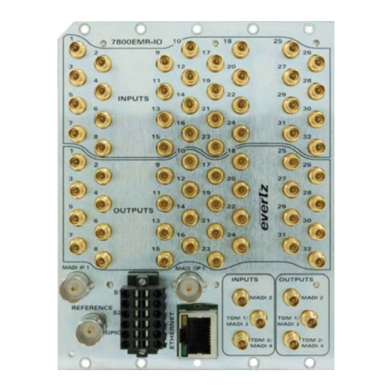
3.1. INSTALLATION OF 7800EMR-IO ON 7800FR FRAME Step 1: Install the 7800EMR-IO rear plate to the 7800 frame with screws provided and make sure the orientation of the rear plate is as shown in Figure 3-1. Figure 3-1: 7800EMR-IO Rear Plate Step 2: Insert the 7800EMR-IO module in the 7800FR Frame and make sure the orientation of the card is correct and it is pushed all the way into the frame. -
Page 17: Front Card Edge Controls And Leds
32x32 AES & MADI Router/Interface FRONT CARD EDGE CONTROLS AND LEDS The 7800EMR-IO front card edges have some key controls and indicators that can help in the installation and debugging processes. Table 4-1 and Figure 4-1 below shows the card edges and describes the expected behavior of each component. -
Page 18: Serial Menu
Through the card-edge’s serial port J6 and using the serial upgrade ribbon cable connected to a PC’s serial port, start HyperTerminal (or equivalent) application. The upgrade ribbon cable supplied has a six pin header socket on one end and a female 9 pin D connector on the other end (Evertz part number WA-S76). -
Page 19: Set Router Mode
7800EMR-IO 32x32 AES & MADI Router/Interface 4.1.3. Set Router Mode Allows the user to set the module to ADMX mode, which means an ADMX Mode external ADMX is required for controlling the routes. Allows the user to set the module to XPT mode, which means the card will XPT Mode operate a standalone router. -
Page 20: Show Board Information
7800EMR-IO 32x32 AES & MADI Router/Interface Click Suppression Allows the user to select a range mono channels Set Mono Select Range Allows the user to enable and disable click suppression to Set Click Suppression all channels or selected range Audio Fault... -
Page 21: Vistalink ® Pro Configuration
- Adding the 7800EMR-IO’s IP Address ® Expand the hardware tree by clicking on the “+” button and the IP address of the 7800EMR-IO module should appear with a green icon to indicate proper communication. Select 7800EMR-IO and right click to “View Configuration...”. -
Page 22: General Tab
7800EMR-IO 32x32 AES & MADI Router/Interface 5.1. GENERAL TAB The General tab displays the information about the Card, Frame Reference, Reference Port 1 & 2 and Frame Reference trap status. Figure 5-3: VistaLINK - General Tab ® Card Information Card Type: Displays the name of the card. - Page 23 7800EMR-IO 32x32 AES & MADI Router/Interface Input 1 Source Select: Allows the user to select the source reference. Options are Frame or Rear Plate. Primary Reference Source: Allows the user to select the primary reference source. Options are Reference Port 1 or Reference Port 2 Fail Safe Mode: Allows the user to configure the fail safe mode for when the primary source reference fails.
-
Page 24: Src (Sample Rate Converter) Control Tab
7800EMR-IO 32x32 AES & MADI Router/Interface 5.2. SRC (SAMPLE RATE CONVERTER) CONTROL TAB The SRC (Sample Rate Converter) Control tab displays the controls for the Audio Bit Resolution, Audio Source Mode, and Audio Channel Bit Mode for 32 AES Stereo Channels. -
Page 25: Audio Pair Control Tab
7800EMR-IO 32x32 AES & MADI Router/Interface Audio Channel Bit Resolution : Allows the user to configure the channel bit resolution. Options are 20 or 24 Audio Bit. Sample Rate Converter: Allows the user to enable or the SRC to be Enabled, Bypassed or Auto Bypassed for each Audio Channel. -
Page 26: Audio Pair Faults
7800EMR-IO 32x32 AES & MADI Router/Interface Audio Pair Mono Reset Duration: Sets the duration before the mono detection begins monitoring again. Range is between 0 sec to 60 sec. 5.4. AUDIO PAIR FAULTS The Audio Pair Faults tab allows the user to Enable or Disable the Phase Reversal traps and Mono traps for 160 stereo channels. -
Page 27: Tdm Status Tab
7800EMR-IO 32x32 AES & MADI Router/Interface Same Phase as Pair 1: This click button control is used to set all Audio Pairs to the same trap enable settings selected for Audio Pair 1 - Phase. Trap Enable: Anti Phase: This control allows the user to enable traps to be sent out on faults on phase reversal on the audio pair selected. -
Page 28: Madi Status Tab
TDM Output SID Status 1 TDM Output SID IP Address: Displays the IP Address of 7800EMR-IO. TDM Output SID Port Number: Displays the TDM Output Port Number of 7800EMR-IO. TDM Output SID Description: Displays the Source ID name of 7800EMR-IO. -
Page 29: Tdm Faults Tab
7800EMR-IO 32x32 AES & MADI Router/Interface 5.7. TDM FAULTS TAB The TDM Faults Tab displays the fault status for the TDM ports and also allows the user to enable or disable sending out traps for TDM presence and error. Figure 5-9: VistaLINK - TDM Faults Tab ®... -
Page 30: Monitoring Tab For Individual Channels Of 7800Emr-Io
MONITORING TAB FOR INDIVIDUAL CHANNELS OF 7800EMR-IO Expand the 7800EMR-IO node by clicking on the “+” button ( ) and all 320 channels of 7800EMR-IO should appear individually with a BNC icon to indicate each channel as seen in Figure 5-11. Figure 5-11: VistaLINK - Individual Channel Tab ®... -
Page 31: Audio Tdm Processing Tab
7800EMR-IO 32x32 AES & MADI Router/Interface Figure 5-12: VistaLINK - Audio TDM Processing Tab ® 5.9.1. Audio TDM Processing Tab Audio Mixer Enable Audio Mixer Enable: The drop down menu allows the user to Enable or Disable the Audio Mixers. -
Page 32: Audio Mono Config Tab
7800EMR-IO 32x32 AES & MADI Router/Interface 5.9.2. Audio Mono Config Tab Audio Mono Config tab allows the user to set the Audio Fault Definitions. Figure 5-13: VistaLINK - Audio Mono Config Tab ® Audio Fault Definition Audio Non PCM Reset Duration: Sets the duration, after a Non PCM fault condition, before the fault condition can be reset. -
Page 33: Audio Tone Generator Tab
7800EMR-IO 32x32 AES & MADI Router/Interface 5.9.3. Audio Tone Generator Tab Audio Tone Generator tab provides access to tone generator parameters Figure 5-14: VistaLINK - Audio Tone Generator Tab ® Audio Tone Generator Audio Tone Enable: This control is used to enable or disable the tone gernerator. -
Page 34: Audio Monitor Tab
7800EMR-IO 32x32 AES & MADI Router/Interface Trap Enable Audio Channel Loss: Trap Enable, when selected, allows for trap messages to be send on fault conditions when the Audio signal is not present. Audio Channel Silent: Trap Enable, when selected, allows for trap messages to be send on fault conditions for Audio Silent. -
Page 35: Audio Control Tab
7800EMR-IO 32x32 AES & MADI Router/Interface 5.9.6. Audio Control Tab Audio Control tab provides access to audio setting parameters. Figure 5-17: VistaLINK - Audio Control ® Audio Setting Audio Sample Rate: Displays the audio sample rate. Audio Delay: This control is used to select the amount of delay for the audio input. - Page 36 7800EMR-IO 32x32 AES & MADI Router/Interface Audio Mixer Enable Audio Mixer Enable: This control is used to enable or disable the Audio Mixer. Audio Mixer Input 1 to Input 4 Gain: This control is used to set the amout of gain on the Audio Mixer.
-
Page 37: Updating Vlpro Server Jar File
UPDATING VLPRO SERVER JAR FILE Products from Evertz are constantly evolving and new features are often added. It is therefore important to update the JAR files in use to provide access to all the latest features or enhancements. It will also necessary to add JAR files for new products. -
Page 38: Figure 6-2: Vistalink Pro - Applying Jar File Updates
7800EMR-IO 32x32 AES & MADI Router/Interface Figure 6-2: VistaLink PRO – Applying JAR File Updates ® You will be prompted to restart the server to enable the change to take effect. Apply as many JAR updates as required before restarting the server. -
Page 39: Upgrading The Firmware On 7800Emr-Io Through Ftp
7800EMR-IO 32x32 AES & MADI Router/Interface UPGRADING THE FIRMWARE ON 7800EMR-IO THROUGH FTP 1. Identify and confirm the IP Addresses of the module and PC/laptop, and ensure that they are on same subnet. 2. Obtain the new firmware and copy to any directory on your computer. (C:\temp) 3. -
Page 40: Figure 7-2: Sample - Ftp Upgrade Window
7800EMR-IO 32x32 AES & MADI Router/Interface Figure 7-2: Sample - FTP Upgrade Window Page - 32 Revision 1.0...
Need help?
Do you have a question about the 7800EMR-IO and is the answer not in the manual?
Questions and answers