Table of Contents
Advertisement
Quick Links
Frame Synchronizer and Distribution Amplifier
© Copyright 2016
EVERTZ MICROSYSTEMS LTD.
5292 John Lucas Drive
Burlington, Ontario
Canada L7L 5Z9
Phone:
+1 905-335-3700
Sales:
sales@evertz.com
Tech Support: service@evertz.com
Web Page:
http://www.evertz.com
Version 0.1, January 2016
The material contained in this manual consists of information that is the property of Evertz Microsystems and is intended solely for the use of
purchasers of the 7847FSEDA series product. Evertz Microsystems expressly prohibits the use of this manual for any purpose other than the
operation of the 7847FSEDA series product. Due to on going research and development, features and specifications in this manual are subject to
change without notice.
All rights reserved. No part of this publication may be reproduced without the express written permission of Evertz Microsystems Ltd. Copies of
this manual can be ordered from your Evertz dealer or from Evertz Microsystems.
7847FSEDA Series
User Manual
Fax: +1 905-335-3573
Fax: +1 905-335-7571
Advertisement
Table of Contents

Related Manuals for evertz 7847FSEDA Series


Summary of Contents for evertz 7847FSEDA Series
- Page 1 Version 0.1, January 2016 The material contained in this manual consists of information that is the property of Evertz Microsystems and is intended solely for the use of purchasers of the 7847FSEDA series product. Evertz Microsystems expressly prohibits the use of this manual for any purpose other than the operation of the 7847FSEDA series product.
- Page 2 This page left intentionally blank...
- Page 3 IMPORTANT SAFETY INSTRUCTIONS The lightning flash with arrowhead symbol within an equilateral triangle is intended to alert the user to the presence of uninsulated “Dangerous voltage” within the product’s enclosure that may be of sufficient magnitude to constitute a risk of electric shock to persons. The exclamation point within an equilateral triangle is intended to alert the user to the presence of important operating and maintenance (Servicing) instructions in the literature accompanying the product.
- Page 4 WARNING Changes or Modifications not expressly approved by Evertz Microsystems Ltd. could void the user’s authority to operate the equipment. Use of unshielded plugs or cables may cause radiation interference. Properly shielded interface cables...
-
Page 5: Table Of Contents
7847FSEDA Series Frame Synchronizer and Distribution Amplifier TABLE OF CONTENTS OVERVIEW ........................... 1 1.1. PRODUCT OPTIONS ......................2 GETTING STARTED ........................5 2.1. INPUT / OUTPUT CONNECTIONS ..................6 2.2. ETHERNET CONNECTIONS ....................7 2.2.1. Ethernet Ports ......................8 2.2.2. Ethernet Status LEDs ....................8 SPECIFICATIONS ......................... - Page 6 5.2.18. SubPresets ......................65 JUMPERS ........................... 67 6.1. LOCAL FAULT MONITORING USING THE GLOBAL FRAME STATUS ......68 6.2. 7847FSEDA SERIES SLOT BLOCKER ................68 UPGRADE PROCEDURES ......................69 7.1. VISTALINK® PRO PRODUCT JAR UPGRADE ..............70 7.2. FIRMWARE UPGRADE ..................... 72 7.3.
- Page 7 7847FSEDA Series Frame Synchronizer and Distribution Amplifier Figures Figure 1-1: 7847FSEDA System Block Diagram....................3 Figure 1-2: 7847FSEDA Audio Block diagram ....................4 Figure 2-1: 7815XX-F-2 Rear Plate Layout ...................... 5 Figure 4-1: 7847FSEDA Status LEDs ......................11 Figure 5-1: 7847FSEDA in VistaLINK PRO Hardware Tree ................
- Page 8 7847FSEDA Series Frame Synchronizer and Distribution Amplifier Tables Table 2-1: Colour Code Wiring for the Current RJ45 Standards..............7 Table 5-1: Video - Supported Input Video Standards ..................22 Table 5-2: Embedded Audio Mixer - Selectable Audio Sources ..............37 Table 5-3: Downmix Mixer - Selectable Audio Sources .................
- Page 9 Evertz products are for informational use only and are not warranties of future performance, either expressed or implied. The only warranty offered by Evertz in relation to this product is the Evertz standard limited warranty, stated in the sales contract or order confirmation form.
- Page 10 7847FSEDA Series Frame Synchronizer and Distribution Amplifier This page left intentionally blank Page - vi Revision 0.1...
-
Page 11: Overview
Synchronizers and Distribution Amplifiers that support SD, HD and 3G ([-3G] option) video formats. The 7847FSEDA series supports one coax and one fiber optic input on a per path basis. Using a software selection process, the fiber optic or coax input signal may be utilized for subsequent module processing that feeds the program outputs (PGM OUT). -
Page 12: Product Options
1.1. PRODUCT OPTIONS This manual covers all variations and ordering options for the 7847FSEDA series platform. There are a number of different possible configurations of the 7847FSEDA. The supported product options can be easily described using the product formula below. All product configurations that satisfy the formula are valid, and are supported by the 7847FSEDA series. -
Page 13: Figure 1-1: 7847Fseda System Block Diagram
7847FSEDA Series Frame Synchronizer and Distribution Amplifier Path 1 Cable PGM OUT1-1 AUDIO Processing Driver Cable PGM OUT1-2 Auto 5.1 Upmix [+UMX2] Driver Audio IntelliGain [+IG2] Video Cable PGM OUT1-3 Monitoring Driver Audio Shuffling, Audio Delay Cable PGM OUT1-4 Driver... -
Page 14: Figure 1-2: 7847Fseda Audio Block Diagram
7847FSEDA Series Frame Synchronizer and Distribution Amplifier Figure 1-2: 7847FSEDA Audio Block diagram Page - 4 Revision 0.1... -
Page 15: Getting Started
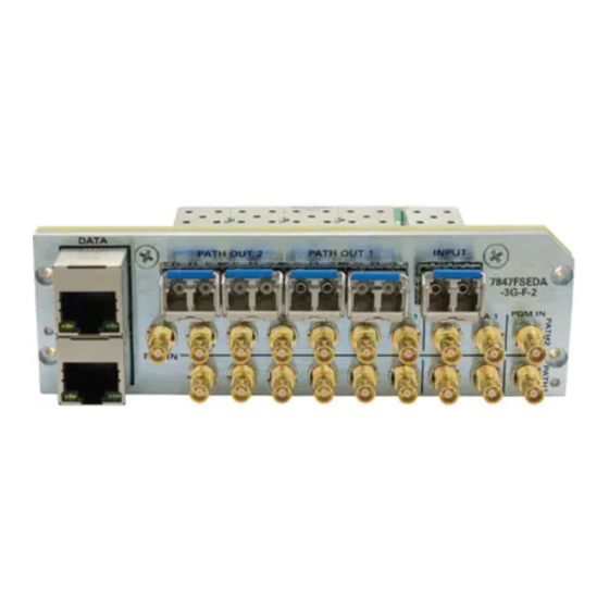
LOCAL FAULT LED will be on (See Section 6.2 for details). For information on mounting the rear plate and inserting the module into the frame see section 3 of the 7700FR manual. Refer to Figure 2-1 for 7847FSEDA series rear plate layout. -
Page 16: Input / Output Connections
7847FSEDA Series Frame Synchronizer and Distribution Amplifier 2.1. INPUT / OUTPUT CONNECTIONS PGM IN: Accepts a 10-bit serial digital video signal (SDI) compatible with SMPTE 259M, SMPTE 292M and SMPTE 425M. The module can be set to receive a specific video standard or set to automatically detect the supplied input video standard. -
Page 17: Ethernet Connections
RJ-45 receptacle of the 7847FSEDA module and the other end into a port of the supporting hub. If you are connecting the 7847FSEDA series module directly to an Ethernet port on a computer, you will have to use a crossover cable. -
Page 18: Ethernet Ports
® 5.1.3 IP for further details. NOTE: The 7847FSEDA series does not currently support SNMP configuration via the CONTROL port. A 7700FC/7800FC must be used for module configuration. DATA: This port is purposed for connection to the facilities data network. This port is not currently used on the 7847FSEDA series. -
Page 19: Specifications
Optical Sensitivity: -21dBm at 2.97GB/s pathological Level A -23dBm at 2.97GB/s color bars 3.4. OPTICAL DIGITAL VIDEO OUTPUT Module: Evertz SFP3T13-2 (Up to 4x modules) Number of Outputs: 2 per module Connector: LC/UPC Fiber: Compatible with Singlemode or 50/62.5µm Multimode Optical Power: -2dBm ±... -
Page 20: Electrical
7847FSEDA Series Frame Synchronizer and Distribution Amplifier 3.6. ELECTRICAL Voltage: +12VDC Power: 32 Watts EMI/RFI: Complies with FCC regulations for class A devices. Complies with EU EMC directive 3.7. PHYSICAL Number of slots 7800FR Frame: 7700FR-C Frame: 3 (slot blocker must be installed for proper installation) Page - 10 Revision 0.1... -
Page 21: Status Leds
Frame Synchronizer and Distribution Amplifier STATUS LEDS 4.1. MODULE STATUS LEDS Figure 4-1 depicts status LEDs for the 7847FSEDA series modules. LEDs are in the same position and perform the same function as the 7815VPDA and 7815IDA series modules. Shaft Module... - Page 22 7847FSEDA Series Frame Synchronizer and Distribution Amplifier This page left intentionally blank Page - 12 Revision 0.1...
-
Page 23: Vistalink Pro Interface
NOTE: When using VistaLINK PRO it is important to ensure that the most recent ® 7847FSEDA series “JAR” control file is installed. See Section 7.1 for details on how to upgrade the 7847FSEDA series VistaLINK PRO JAR file. ®... -
Page 24: System Configuration
NOTE: If any of the cooling fan statuses report a failure, the module should be powered down immediately to avoid overheating and subsequent damage to the module. Contact Evertz for further assistance in replacing the failed modules. Figure 5-2: System Configuration - General Tab To enable/disable a specific fault trap, check/uncheck the corresponding checkbox. -
Page 25: Reference
The video reference signal can be sourced from either the modules REF input connection on the rear plate, or either of the FRAME REF inputs on the 7800FR or 7700FR-G frames. The 7847FSEDA series supports locking to 525i/59.94Hz and 625i/50Hz bi-level reference signals, and 1080i/59.94Hz and 1080i/50Hz tri-level reference signals. - Page 26 7847FSEDA Series Frame Synchronizer and Distribution Amplifier Global Status Genlock Standard: This field displays if a valid video reference has been detected on the selected reference input. It reports the detected reference video standard when a valid reference is applied.
-
Page 27: Change Product
PRO global configuration view. NOTE: A unique checksum must be generated to support a product string change on the 7847FSEDA. Please contact Evertz if you are interested in upgrading the feature set of your 7847FSEDA. Page - 17 Revision 0.1... -
Page 28: Figure 5-5: System Configuration - Change Product Tab
Product Name: The product name entry area will be used to enter in the name of the product that the module will be upgraded to. Checksum: The checksum location will contain the verification code that the Evertz sales department will provide when the options have been purchased. -
Page 29: Fiber Rx
7847FSEDA Series Frame Synchronizer and Distribution Amplifier 5.1.5. Fiber RX The Fiber RX tab contains all control and status related to the optical fiber SFP receiver. If the Fiber receiver SFP is not installed in the correct location on the 7847FSEDA rear-plate, the status will report ‘Not detected’... -
Page 30: Fiber Tx
7847FSEDA Series Frame Synchronizer and Distribution Amplifier 5.1.6. Fiber TX The Fiber TX tab contains all control and status related to the optical fiber SFP transmitters. The 7847FSEDA supports up to 4 SFP modules (2 modules per video path). If the Fiber transmitter SFP is not installed in the specific location on the 7847FSEDA rear-plate, the status will report ‘Not detected’... -
Page 31: Video Path Configuration
7847FSEDA Series Frame Synchronizer and Distribution Amplifier 5.2. VIDEO PATH CONFIGURATION 5.2.1. Video The Video tab contains all controls related to core video configuration as well as basic monitoring information regarding the input video sourced to the 7847FSEDA. Figure 5-8 illustrates the layout of the controls in the VistaLINK®... -
Page 32: Table 5-1: Video - Supported Input Video Standards
7847FSEDA Series Frame Synchronizer and Distribution Amplifier 1080i/59.94Hz 720p/59.94Hz 525i/59.94Hz 1080i/50Hz 720p/50Hz 625i/50Hz 1080p/59.94Hz (425M level A) [-3G option only] 1080p/59.94Hz (425M level B) [-3G option only] 1080p/50Hz (425M level A) [-3G option only] 1080p/50Hz (425M level B) [-3G option only]... - Page 33 7847FSEDA Series Frame Synchronizer and Distribution Amplifier Horizontal Phase Offset: This control allows users to set the horizontal timing of the output video with respect to the reference input set by the Reference Select control. There are independent H Phase Offset controls for each video path. Setting H Phase Offset = 0 maintains the horizontal timing alignment of the output video with respect to the reference input.
-
Page 34: Video Monitoring
Frame Synchronizer and Distribution Amplifier 5.2.2. Video Monitoring The 7847FSEDA series modules support advanced audio & video monitoring, referred to as AVM. This advanced monitoring includes metrics for detecting potential issues in the video signal. Figure 5-9 illustrates the layout of the controls in the VistaLINK® PRO configuration view. - Page 35 7847FSEDA Series Frame Synchronizer and Distribution Amplifier Video Black Duration: This control sets the number of consecutive video frames that must contain active picture content below 7 IRE before triggering a video black fault condition. The value range is from 4 to 9996 frames in increments of 4 video frames.
- Page 36 7847FSEDA Series Frame Synchronizer and Distribution Amplifier pixels above the white error level exceeds the number of pixels (threshold) defined by the Error Quantity control. Black/White Level Error Duration: This control sets the number of seconds of consecutive video fields/frames that must be flagged as having black/white level errors before triggering the corresponding black/white level error fault condition.
- Page 37 7847FSEDA Series Frame Synchronizer and Distribution Amplifier Video Frozen: This trap will trigger when a set of consecutive input video frames of length greater than Video Frozen Duration all containing video activity (motion) below the video noise level. This trap will clear when a set of consecutive input video frames of length greater than Video Frozen Timeout all containing video activity (motion) above the picture noise level.
-
Page 38: Reference
Frame Synchronizer and Distribution Amplifier 5.2.3. Reference The 7847FSEDA series supports fully independent timing on each video processing path. Each video processing path can be configured to either lock to the input video timing, or the external reference signal timing. The Reference tab within the video configuration provides the controls and status related Figure 5-10 to video path specific reference controls. -
Page 39: Video Proc
7847FSEDA Series Frame Synchronizer and Distribution Amplifier Reference Traps To enable/disable a specific fault trap, check/uncheck the corresponding checkbox. Genlock Valid: This trap will trigger to report an invalid Genlock/reference signal. A reference signal is considered invalid if it is not present, unsupported by the module or has a frame rate mismatch with the detected input video standard on the corresponding video path. - Page 40 7847FSEDA Series Frame Synchronizer and Distribution Amplifier NOTE: All Video Proc controls affect the video in real time. H&V frequency bands will cause hits to the video while a new filter is loaded. Video Proc RGB Clip: The RGB Clip parameter controls RGB clipping/colour legalization process. When set to enable, the module will clip any illegal levels of R, G, and B (individually) to their respective Black and White Levels.
-
Page 41: Image Enhancement
7847FSEDA Series Frame Synchronizer and Distribution Amplifier Reset Button: By pressing the Reset button, all Video Processing parameters in the Video Proc control tab will return to their default value. 5.2.5. Image Enhancement The Image Enhancement tab contains controls related to active picture image enhancement adjustments. -
Page 42: Audio
7847FSEDA Series Frame Synchronizer and Distribution Amplifier Vertical Intensity: This control selects the intensity of the vertical enhancement process as a ratio of the Horizontal enhancement. The range is from 0% to 100% in increments of 25%, where 0% refers to no vertical enhancement and 100% provides a vertical enhancement that is equivalent to the applied horizontal enhancement. - Page 43 7847FSEDA Series Frame Synchronizer and Distribution Amplifier Audio Control Audio Delay: This control allows the user to adjust the audio delay +/- 350.00 ms. This delay is relative to the delay that the module automatically inserts to match video path delay. The audio delay can be adjusted with single sample precision.
-
Page 44: Audio Monitoring
Audio Group <1-4>: These audio traps monitor the presence of embedded audio groups on the input video. 5.2.7. Audio Monitoring The 7847FSEDA series modules support advanced audio & video monitoring, referred to as AVM. This advanced monitoring includes metrics for detecting potential silence or loudness in the audio signals. - Page 45 7847FSEDA Series Frame Synchronizer and Distribution Amplifier Audio Over Duration: This control sets the duration, in number of consecutive audio samples, that the audio must be at or above the Audio Over level before a fault condition exists. The value range is from 3 to 255 audio samples in one-sample increments.
-
Page 46: Embedded Aic
7847FSEDA Series Frame Synchronizer and Distribution Amplifier 5.2.8. Embedded AIC The Embedded AIC (Audio Input Correction) tab contains controls for adjustment of the 16 embedded audio channels present on the input video. This purpose of audio input correction is to apply correction to an input signal before it is routed through other audio processing modules. -
Page 47: Embedded Audio Mixer
7847FSEDA Series Frame Synchronizer and Distribution Amplifier 5.2.9. Embedded Audio Mixer The Embedded Audio Mixer tab contains controls for audio routing, audio gain, and audio inversion for the 16 embedded audio channels present on the program output video. Each output audio channel mixer consists of two independently selectable sources (X &... -
Page 48: Figure 5-16: Video Path Configuration - Embedded Audio Mixer Tab
7847FSEDA Series Frame Synchronizer and Distribution Amplifier Figure 5-16: Video Path Configuration - Embedded Audio Mixer Tab Source – X & Y: These controls allow the user to route one of the selectable mixer input audio sources to the Corresponding input (X or Y) of the embedded audio output channel mixer. -
Page 49: Downmix
7847FSEDA Series Frame Synchronizer and Distribution Amplifier 5.2.10. Downmix The Downmix audio processing module provides the ability to downmix 5.1 surround sound to 2- channel (stereo) sound, or single channel (mono) sound. The Downmix audio processor can be configured to utilize common downmixing algorithms (Lo/Ro, Lt/Rt) and is also fully user configurable. - Page 50 7847FSEDA Series Frame Synchronizer and Distribution Amplifier LFE Gain: This control allows the user to adjust the gain applied to the LFE channel. This control is in effect only when LFE Gain is selected for LFE Mixing control. The range for this value can be set from -20.0dB to 20.0dB in 0.1 dB increments.
-
Page 51: Downmix Mixer
7847FSEDA Series Frame Synchronizer and Distribution Amplifier 5.2.11. Downmix Mixer The Downmix Mixer tab contains controls for audio routing, audio gain, and audio inversion for the Downmix audio processing module input channels. Each Downmix input audio channel mixer consists of two independently selectable sources (X & Y) with each source having its own gain and inversion controls. -
Page 52: Upmix [+Umx2]
NOTE: Please contact Evertz if interested in adding the Upmix [+UMX2] product option. When operating in Auto mode, the Upmix audio processor can automatically detect the presence of 5.1 surround sound on its input audio channels. If 5.1 surround sound is detected, the upmix audio processing module simply passes the audio through. - Page 53 7847FSEDA Series Frame Synchronizer and Distribution Amplifier Figure 5-19: Video Path Configuration - Upmix Tab Upmix Mode: This control allows the user to set the upmix audio processing module to automatically determine if the audio needs to be upmixed. It can automatically detect the presence of 5.1 surround sound on its inputs.
-
Page 54: Table 5-4: Upmix - Lfe Gain Levels
7847FSEDA Series Frame Synchronizer and Distribution Amplifier LFE Gain: This control allows the user to set LFE channel gain at the upmix audio processing module output. Use the drop down menu to select the appropriate amount of gain to be applied. -
Page 55: Upmix Mixer [+Umx2]
7847FSEDA Series Frame Synchronizer and Distribution Amplifier 5.2.13. Upmix Mixer [+UMX2] The Upmix Mixer tab contains controls for audio routing, audio gain, and audio inversion for the Upmix audio processing module input channels. Each Upmix input audio channel mixer consists of two independently selectable sources (X &... -
Page 56: Figure 5-18: Video Path Configuration - Upmix Mixer Tab
7847FSEDA Series Frame Synchronizer and Distribution Amplifier Figure 5-18: Video Path Configuration - Upmix Mixer Tab Upmix Input Channel Select: These option buttons allow the user to toggle between configuration of Upmix input channel mixers L, R, C, LFE and Ls, Rs, Passthru L, Passthru R. -
Page 57: Intelligain [+Ig2]
[+IG2] ® IntelliGain is a technology developed by Evertz to control the loudness of audio programs on the fly. ® More specifically, it calculates the perceived loudness of the input audio and modifies the audio to ensure that the long-term average loudness level is at the target level. IntelliGain works with mono, ®... -
Page 58: Figure 5-19: Video Path Configuration - Intelligain
7847FSEDA Series Frame Synchronizer and Distribution Amplifier Product Option Mixer Sources Mute DMX channels 1-16 All Products Mono mix DMX channels (8 pairs – 1&2, 3&4, etc.) Down mix L, R Down mix mono Upmix [+UMX2] Up mix L, R, C, LFE, Ls, Rs, passthru L, passthru R... -
Page 59: Figure 5-20: Video Path Configuration - Intelligain Configuration Tab
7847FSEDA Series Frame Synchronizer and Distribution Amplifier Module & Channel Select: These option buttons allow the user to toggle between configuration of IntelliGain Module 1 & 2 and input channel mixers 1-4 and 5-8. ® Source – X & Y: These controls allow the user to route one of the selectable mixer input audio sources to the corresponding input (X or Y) of the IntelliGain input channel mixer. - Page 60 7847FSEDA Series Frame Synchronizer and Distribution Amplifier Program Configuration Source: This control defines how the input audio channels are grouped together into programs for the IntelliGain audio loudness processing. Up to eight channels can be ® grouped together in individual programs, where each program contains its own metadata. IntelliGain ®...
-
Page 61: Table 5-7: Intelligain
7847FSEDA Series Frame Synchronizer and Distribution Amplifier Table 5-7 provides a list of IntelliGain program to input audio channel mapping guidelines. For ® example, configuration 5.1+2, program 1 (P1) is mapped to channel CH1 to CH6 and program 2 (P2) is mapped to channel CH7 to CH8. -
Page 62: Table 5-8: Intelligain
7847FSEDA Series Frame Synchronizer and Distribution Amplifier Abbreviations Description Program Channel Left or left front Right or right front Center or mono Low frequency effect Left surround Right surround Back surround left Back surround right Table 5-8: IntelliGain - Channel Mapping Abbreviations ®... -
Page 63: Figure 5-21: Video Path Configuration - Intelligain
7847FSEDA Series Frame Synchronizer and Distribution Amplifier 5.2.14.3. IntelliGain Program Control [+IG2] ® The IntelliGain Program Control tab contains the program configuration controls for the individual ® IntelliGain audio programs. Figure 5-23 illustrates the layout of these controls in the VistaLINK ®... - Page 64 7847FSEDA Series Frame Synchronizer and Distribution Amplifier NOTE: Only the valid programs will be selectable for configuration. The valid programs are determined by the value of the Program Configuration Source control. Program IntelliGain IntelliGain State: This control allows the user to set the master switch for the IntelliGain processor, which is used for the given audio program.
- Page 65 7847FSEDA Series Frame Synchronizer and Distribution Amplifier Film Light: This profile is used to compress/expand light movies or program content such as dramas or content with less dynamic range. Max Boost: 6 dB (below –53 dB) Boost Range: –53 to –41 dB (2:1 ratio) Null Band Width: 20 dB (–41 to –21 dB)
- Page 66 7847FSEDA Series Frame Synchronizer and Distribution Amplifier minor/major/critical fault trap to be sent to the registered trap alarm servers. The value range is 0.5 sec to 240 sec in increments of 0.5 secs. Clear Duration: This control allows the user to define the amount of time that the program audio loudness level must remain below the minor/major/critical program threshold to trigger the corresponding minor/major/critical fault trap to be cleared.
- Page 67 7847FSEDA Series Frame Synchronizer and Distribution Amplifier Loudness Range Low: This field displays the lowest calculated loudness value within the duration of the Integrated Loudness calculation, given the exclusions and thresholds used as described above in the calculation of the Loudness Range. This control is used for monitoring purposes only. The value...
-
Page 68: Sid (Source Identification)
7847FSEDA Series Frame Synchronizer and Distribution Amplifier Figure 5-22: Video Path Configuration - IntelliGain Traps Tab ® 5.2.15. SID (Source Identification) Source Identification (termed Source ID) provides a useful method for tagging the video signal with a VANC data packet as it is processed by the module. With each module appending its own source ID tag into the VANC region;... -
Page 69: Figure 5-23: Video Path Configuration - Sid Tab
7847FSEDA Series Frame Synchronizer and Distribution Amplifier All data within the source ID packet is ASCII encoded to allow for simple decoding and monitoring of any element within the source ID packet. The SID tab contains all controls relating to Source ID processing. It allows the user to specify the contents of the source ID VANC packet that will uniquely identify the module and act as its fingerprint/signature on the processed video signal. -
Page 70: Anc Passthru
7847FSEDA Series Frame Synchronizer and Distribution Amplifier Base Label: This field allows the user to set the primary identification of the module/video signal. The base label is a maximum of 16 characters. Alias Label: This field allows the user to set additional secondary identification of the module/video signal. - Page 71 7847FSEDA Series Frame Synchronizer and Distribution Amplifier • Direct ANC PassThru overrides Mapped ANC PassThru when it is enabled and Input Video Standard is identical to the Output Video Standard • When Direct ANC PassThru is disabled or invalid, Mapped ANC PassThru rules are applied.
-
Page 72: Figure 5-24: Video Path Configuration - Anc Passthru Tab
7847FSEDA Series Frame Synchronizer and Distribution Amplifier Figure 5-24: Video Path Configuration - ANC PassThru Tab Direct ANC PassThru Direct ANC PassThru: This control allows the user to Enable or Disable Direct ANC data passthru for ANC data that is not processed through the module to pass through without getting striped on the output video signal. -
Page 73: Table 5-10: Anc Passthru - Mapped Anc Packet Pass Through Status Values
7847FSEDA Series Frame Synchronizer and Distribution Amplifier DID: This control allows the user to set the DID of the ANC packet to be passed through. Valid range is 0x01 to 0xFF. SDID: This control allows the user to set the SDID of the ANC packet to be passed through. Valid range is 0x01 to 0xFF. -
Page 74: Presets
7847FSEDA Series Frame Synchronizer and Distribution Amplifier 5.2.17. Presets The Presets tab provides the facilities for naming, loading, storing and triggering user defined video path presets. It also provides the facility to load default values for all video path parameters. Figure 5-27 illustrates the layout of these controls in the VistaLINK®... -
Page 75: Subpresets
7847FSEDA Series Frame Synchronizer and Distribution Amplifier Input Vid Std Preset Trigger: This control allows the user to automatically trigger the loading of a video path user preset based on the detected input video standard. For each video path user preset,... - Page 76 7847FSEDA Series Frame Synchronizer and Distribution Amplifier Figure 5-28: Video Path Configuration - SubPresets Tab User Sub-preset Single Load These controls provide the facilities to load a single sub-preset XML configuration file into a video path user preset. Configuration File: By clicking the Browse button, the user can locate the sub-preset XML configuration file to be loaded.
-
Page 77: Jumpers
7847FSEDA Series Frame Synchronizer and Distribution Amplifier JUMPERS Figure 6-1 and Figure 6-2 provide the locations of the jumpers and LEDs on the 7847FSEDA series boards. Frame Status ON/OFF MODULE STATUS Serial Figure 6-1: Location of Jumpers - Top View Main Module... -
Page 78: Local Fault Monitoring Using The Global Frame Status
7847FSEDA Series Slot Blocker The 7847FSEDA series of modules can be installed in either the 7700FR-C or the 7800FR frames. These modules are designed to take two slots in the Evertz 7800FR frame and three slots in the 7700FR-C. Modules can fit into two slots in a 7800FR frame because the 7800FR allows modules to consume more power on a per slot basis than the Evertz 7700FR-C. -
Page 79: Upgrade Procedures
7847FSEDA Series Frame Synchronizer and Distribution Amplifier UPGRADE PROCEDURES There are multiple components of the module operation that can be upgraded. These include: • VistaLINK PRO Product JAR upgrade ® • Firmware upgrade • Product String upgrade This section outlines the procedures for performing these module upgrades. -
Page 80: Vistalink® Pro Product Jar Upgrade
7847FSEDA Series Frame Synchronizer and Distribution Amplifier 7.1. VISTALINK® PRO PRODUCT JAR UPGRADE Open VISTALINK PRO Server and navigate to Help > Apply Update > Product. When the window ® opens you want to select the latest .jar file for the 7847FSEDA, from its saved location on the computer and select Open. -
Page 81: Figure 7-2: Vistalink Pro Jar Upgrade - Module Dropdown Menu
Navigate the hardware tree on the left side of the version information window to select the 7847FSEDA module. The VISTALINK® PRO Product Version reported in the top right corner of the window should match the new version. If it does not, please contact Evertz for further assistance. Figure 7-3: VistaLINK PRO JAR Upgrade - Version Information Window ®... -
Page 82: Firmware Upgrade
7847FSEDA Series Frame Synchronizer and Distribution Amplifier 7.2. FIRMWARE UPGRADE A firmware upgrade can be accomplished through VistaLINK® PRO firmware upgrade facilities. All 7847FSEDA modules within the same 7700FR/7800FR frame can be upgraded simultaneously or one- by-one. However, it is more convenient to upgrade them simultaneously. -
Page 83: Figure 7-5: Firmware Upgrade - Version Information Window
NOTE: If any of the 7847FSEDA modules do not properly upgrade the firmware, please power-cycle those boards and retry the procedure exclusively on the failed boards. If the issue still persists, contact Evertz for further assistance. Page - 73 Revision 0.1... -
Page 84: Product String Upgrade
PRO to successfully update the product strings. ® NOTE: Please contact Evertz to obtain the correct checksum values based on the reported 7847FSEDA module serial numbers to be updated. Each 7847FSEDA module product string must be updated individually. To upgrade the 7847FSEDA... -
Page 85: Figure 7-7: Product String Upgrade - 7847Fseda Global Configuration View
NOTE: If any of the 7847FSEDA modules do not properly upgrade the product string, please power-cycle those boards and retry the procedure exclusively on the failed boards. If the issue still persists, contact Evertz for further assistance. Page - 75... -
Page 86: Appendix A - Version Information
7847FSEDA Series Frame Synchronizer and Distribution Amplifier APPENDIX A – VERSION INFORMATION 8.1. HARDWARE OPTIONS This manual covers the following hardware options: • 7847FSEDA-3G-F-2 • 7847FSEDA-HD-F-2 8.2. SOFTWARE VERSIONS This manual has been written using the following software versions. Functionality may not be identical to the manual description if the module is operating with a different firmware or VistaLINK®...
Need help?
Do you have a question about the 7847FSEDA Series and is the answer not in the manual?
Questions and answers