
Related Manuals for Motcom BeCOMS


Summary of Contents for Motcom BeCOMS
- Page 1 UserManual ® ® BeCOMS BCom | Bearing Condition Monitoring Part No.: 1 900 00 00000 Release: 220601...
- Page 2 BeCOMS ® ® User Manual Table of revision Version Chapter Changes Release Original edition 01.06.2022 Imprint Address of Manufacturer motcom GmbH Kurt-Schumacher-Str.28-30 66130 Saarbrücken / Germany +49 (0) 681 8837904-0 +49 (0) 681 8837904-19 Email info@motcomgmbh.com Internet www.motcomgmbh.com Page ii...
-
Page 3: Table Of Contents
4.3 System measured values 1 (Default screen) ...........4.6 4.4 System measured values 2 ...............4.6 4.5 Graphic overview ..................4.6 4.5.1 BeCOMS graphical data indicator .............4.6 4.6 SRE advanced infos ..................4.7 4.6.1 SRE advanced infos 1 ...............4.7 4.6.2 SRE advanced infos 2 ...............4.7 4.7 Parameter setup ..................4.7... - Page 4 ® User Manual 5 Installation and Commissioning ............. 5.1 5.1 Installation Position ...................5.1 5.2 SRE Mechanical Adjustments ..............5.2 5.3 Installation of Data Logger PC and BeCOMS Software ......5.3 ® 6 Commissioning ................6.1 6.1 Pre-Commissioning Checks ..............6.1 6.2 Syncronization of the BeCOMS Sensor SRE with the firing TDC of the ®...
- Page 5 BeCOMS ® ® User Manual 10 Spare Parts................10.1 11 Connection Assembly Instructions ..........11.1 11.1 Connection Cable - RS485 PCI Card to Evaluator ........11.1 11.2 Assembly of the plug M23 ..............11.4 12 Appendix ..................12.1 Page v Release...
- Page 6 BeCOMS ® ® User Manual Page vi Release 220601...
-
Page 7: General
By means of the ® nameplates of each items the BeCOMS system can be clearly identified. ® The operating instructions are to be kept available with the BeCOMS system at ® all times. The operating instructions contain important notes regarding system operation which are intended to ensure safe, appropriate and economical system operation at all times. -
Page 8: Copyright
1.3 Copyright These operating instructions may be used only by authorised personnel. They may only be given to third parties with the written consent of motcom GmbH. All documents are protected under copyright law. Forwarding and duplication of documents, in whole or in part, is not permitted unless authorised in writing. -
Page 9: Declaration Of Conformity
BeCOMS ® ® User Manual 1.5 Declaration of Conformity EMC-Directives: 2014/30/EU Manufacturer motcom GmbH ® Kurt-Schumacher-Str. 28-30 D - 66130 Saarbrücken / Germany Phone +49 681 8837904-0 Fax: +49 681 8837904-19 We declare on our own responsibility, that the products... -
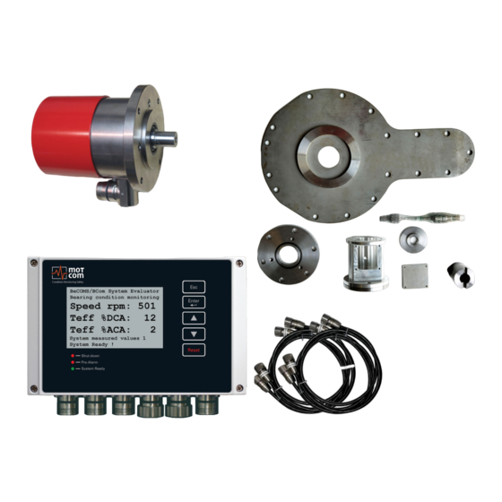
Page 10: Scope Of Delivery
® Serves as a local control and for evaluation and display of all values. It can transmit all data via RS485 interface to a computer running the BeCOMS Data_ ® Logger software (optional) for enhanced visualisation and data storage. The Data_ Logger and motcom Analysis software serves as an offl... - Page 11 ® - BeCOMS Data_Logger Software ® - CD incl. Software installation fi les and a soft copy of this User Manual • Software motcom Loganalyser software, an auto ® analysis tool for BeCOMS Logfi les. ® Page 1.5 Release 220601...
-
Page 12: List Of Nomenclature / Abbreviation
BeCOMS ® ® User Manual 1.7 List of Nomenclature / Abbreviation Abbreviation Description BeCOMS Bearing Condition Online Monitoring System ® Evaluator Control Device IPxx International Protection Light Emitting Diode Liquid Cristal Display Personal Computer PCIe Peripheral Component Interconnect Express... -
Page 13: General Technical Data
BeCOMS ® ® User Manual 2 General Technical Data 2.1 Technical Data of Slip Ring Encoder and Evaluator In this chapter we will give you an overview of the main technical data, ordering options and a brief block-wiring diagram. For a detailed pin layout and technical drawings, please refer to Chapter 12 Appendix. -
Page 14: Versions Of Becoms ® Systems And Software
BeCOMS ® ® User Manual 2.2 Versions of BeCOMS Systems and Software ® Table 2.1 Features (x = included, o = optional, - = not included) Hardware Professional Advanced Basic Power Supply 24V DC +30/-25% Sensitivity adjustable in 5 Steps... - Page 15 User Manual Software PC (Logger, Data_Display) Professional Advanced Basic Required Software shipped with system Logger version for 2, 4 or 6 BeCOMS systems ® included Displays Relais Status Displays Thermosignal in % and mV Displays Thermosignal AC eff. in % alarm level Displays Thermosignal AC eff.
-
Page 16: Connection Diagram
BeCOMS ® ® User Manual 2.3 Connection Diagram The SRE sensor needs to be connected to the Evaluator connector 6 (see Fig. 2.1). Ports 1-3 are reserved for 24V power supply, relay output and serial data link, respectivley. For connector details please refer to Chapter 12 Appendix. -
Page 17: System Overview
It can transmit all data via RS485 interface to a computer running the BeCOMS Data_Logger software (optional) for enhanced visualisation and ® data storage. The Data_Logger and motcom Analysis software serves as an offl ine analysis tool • one Set of mechanical parts and cable for mounting the SRE at the engine... -
Page 18: Slip Ring Encoder Sre
Info: The shaft and the mounting fl ange are determined, designed and manufactured by motcom GmbH or by its authorized partners for each engine type. Only in this case correct operation and trouble-free transmission of measurement signals are guaranteed. -
Page 19: Evaluator
) and one reset button The Evaluator can be operated between 0-70°C and 0-80% relative humidity, suitable for installation close to the engine. It displays all measurement values and parameters and is used for diagnostics of the BeCOMS system. ®... - Page 20 GmbH, the settings of the Evaluator should not be changed. The Evaluator does not require regular maintenance. Note: Available Firmware updates are only to be applied by approved service technicians. Firmware updates are free of charge. Please contact motcom GmbH or an authorized representative for details and further information. Page 3.4 Release...
-
Page 21: Mechanical Adapter And Cable
As a result, the shaft and the SRE are damaged, which leads to the failure of the BeCOMS system. ® A guarantee in the event of damage is excluded by motcom GmbH! Fig. 3.4 Mechanical parts and assembled cable Page 3.5 Release... - Page 22 Fig. 3.5 shows an example of the adaptation with all the individual parts required. Alignment errors cause high wear and tear and consequential damage / failure on the shaft and SRE. A guarantee in the event of damage is excluded by motcom GmbH! Fig. 3.5 Example for an adaption Page 3.6...
- Page 23 BeCOMS ® ® User Manual Table 3.1 Mechanical parts, shown in Fig. 3.5 Intermediate housing Radial cylinder roller bearing Adapter flange Radial shaft seal Isolation washer O-ring Engine seal O-ring Cover 50-53 Cylinder screws Adapter shaft Cylinder screws Cover seal...
-
Page 24: Optional Data Logger Pc With Data_Logger Software
® ® User Manual 3.4 Optional Data Logger PC with Data_Logger Software Advanced or BeCOMS This chapter only applies if you are running a BeCOMS ® ® Professional system! Otherwise, the following information can be ignored. The BeCOMS Data_Logger Software enables the user to: ®... - Page 25 ® **) The RS485 cable lenght must not exceed 400 m motcom GmbH provides optionally either the necessary hardware to convert the RS485 signal of the Evaluator into a standard RS232 PC-signal or a PCI/PCIe card installed in the computer (see Chapter 10 Spare Parts).
- Page 26 BeCOMS ® ® User Manual Page 3.10 Release 220601...
-
Page 27: Functional Description
® User Manual 4 Functional Description In this chapter, first we want to give the user an overview of the measurement principle (see Fig.4.) for a better understanding how the BeCOMS system works. ® The BeCOMS system can be used on combustion engines and electrical motors, ®... - Page 28 ® User Manual Fig. 4.2 Realizing of a redundant thermovoltage measurement in SRE sensor The BeCOMS system is able to precisely detect and localise a beginning failure ® even before it affects the engine performance, using advanced analysis of the thermovoltage signal combined with other measured values and stored engine- specific data.
- Page 29 The thermovoltage and engine rotation speed are displayed at the control device (Evaluator) and optionally remotely on a PC. The information is displayed graphically to ease further decicions on e.g. engine load and/or maintenance, making BeCOMS ® an effective and invaluable tool to reduce engine downtime and maintenance costs.
-
Page 30: Operating Elements/Settings & Parameters
LEDs that indicate the current system status. As soon as the Evaluator is powered up, the initial info screens are shown for several seconds, and then the display switches to default screen (shown in Fig.4.5). Fig. 4.5 Evaluator default screen:current BeCOMS measured values ®... -
Page 31: Menu Structure
Hardware values ...3.6. Note: Enter The numerical indexes correspond to the Menu items are scrolled with arrow Sublevel entry with button chapter numbers from the BeCOMS buttons : Sublevel exit to User Manual. higher level with button Page 4.5 Release... -
Page 32: System Measured Values 1 (Default Screen)
Voltage Tabs [mV]: Measured values 2 absolute thermovoltage in mV Screenshot 4.5 Graphic overview Graphic overview 4.5.1 BeCOMS graphical data indicator The displayed bars are: RPM: engine rotation speed in RPM Teff %ACA: effective value of thermovoltage in percents of... -
Page 33: Sre Advanced Infos
ISs: the current value at the 0 channel of Displays advanced system incremental encoder (0 or 1) values 2 4.7 Parameter setup Provides access to BeCOMS parameters, ® Evaluator settings and test features for viewing and changing. Parameter Setup Page 4.7... -
Page 34: Setup Parameter
User Manual 4.7.1 Setup Parameter Level 1 Level 2 Level 3 Descriptions View and change BeCOMS parameters. ® If the sublevel was entered, pressing [Esc] restarts the Evaluator (see Table 1 on page 4.9). To get write access to this parameter, a PIN Setup Parameter must be entered (see Table 2 on page 4.11) - Page 35 BeCOMS ® ® User Manual Table 1 Setup Parameter Details Level 1 Level 2 Level 3 Descriptions The value of DC main alarm level in the range of 0 to 5. The higher the value, the less sensitive is the system.
- Page 36 BeCOMS ® ® User Manual Level 1 Level 2 Level 3 Descriptions Time interval between test pulses, possible values: 1 min to 10 min. Test pulses help to check if the SRE sensor functions correct. TS Test Time The length of test pulse.
- Page 37 BeCOMS ® ® User Manual Table 2 Setup CPU Details Level 1 Level 2 Level 3 Descriptions Brightness of Evaluator LC display in the range of 5 to 100. The higher the value, the brighter is the display. LCD brightness...
- Page 38 BeCOMS ® ® User Manual Table 3 Test Features Details Level 1 Level 2 Level 3 Descriptions Switch the Ready relay ON and OFF Read Relay Switch the Alarm 1 relay ON and OFF. Alarm Relay Switch the Alarm 2 relay ON and OFF.
-
Page 39: Installation And Commissioning
® personnel from motcom GmbH or its authorized representatives only. The installation procedure includes training for the site operation personnel. The commissioning data will be provided to the customer as part of the training for later reference. -
Page 40: Sre Mechanical Adjustments
Example for an Installation Fig. 5.2 Cut out model of a sample installation 5.2 SRE Mechanical Adjustments The SRE must only be replaced by personnel from motcom GmbH or its authorized representatives. Installation and replacement of the SRE requieres careful mechanical alignment as well as a precise synchronisation with the engine the SRE is installed to. -
Page 41: Installation Of Data Logger Pc And Becoms ® Software
® User Manual 5.3 Installation of Data Logger PC and BeCOMS Software ® Attention This chapter only applies if you are running a BeCOMS Advanced or ® BeCOMS Professional system! ® The Data_Logger and Data _Indicator software comes pre-installed with the supplied Data Logger PC. - Page 42 BeCOMS ® ® User Manual Page 5.4 Release 220601...
-
Page 43: Commissioning
® User Manual 6 Commissioning A proper cabling between SRE, Evaluator and PC is required to achieve an interference-free signal transmission and thus for the function of the BeCOMS ® system. To ensure this, the following Pre-Commissioning-Checks must be done. -
Page 44: First Cylinder
6.2 Syncronization of the BeCOMS Sensor SRE with the firing TDC of the ® first cylinder At the installation of the BeCOMS sensor SRE an one time calibration of the ® incremental encoder has to be performed. This involves synchronising the neutral point of the incremental encoder with the firing Top Dead Center (TDC) of cylinder 1 by finding offset between them. -
Page 45: Data Sampling
BeCOMS systems on a single computer. The measured values and events will ® be monitored and displayed continuously on the computer, and stored in a distinct directory on the hard disk for each connected BeCOMS system. ® Page 6.3 Release... -
Page 46: Alarm Setting And Triggering
The BeCOMS ® recording, displaying and storing data! For example, the following set of conditions should be met in BeCOMS in order to ® trigger a Main Alarm: 1) The GREEN READY LED has to be on. - Page 47 User Manual Depending on the pre-set alarm level and on wiring to the engine site alarm devices, Main Alarm alerts the operator that the tolerated level has been exceeded, indicating that further investigation of BeCOMS signals is needed, and may ®...
-
Page 48: Alarm Resetting
BeCOMS ® ® User Manual 6.5 Alarm Resetting • In case of a Pre-Alarm triggered: If the conditions for a Pre-alarm does not persists after pre-set time period, the Pre-Alarm will be reset automatically by the system. • In case of a Main-Alarm triggered: The Main-Alarm will not be reset automatically by the system even after the conditions that led to it are not met any more. -
Page 49: Becoms ® Data_Logger Measurement Data Storage And Management
BeCOMS Data_Logger is a PC program for displaying and storing the measured ® data. For detailed information on Logger software please refer to the BeCOMS Data_ ® Logger user manual. Data_Indicator software is used for reading and analysing the BeCOMS data files. -
Page 50: Compressing Data Files
YYYY: year, i.e. 2022 MM: month, i.e. 01 DD: day, i.e. 17 of the BeCOMS set on the Engine XXX ® using “WinRAR” follow these instructions: 1) Click on the desired data file which is to be compressed with the right button of the mouse. - Page 51 BeCOMS ® ® User Manual Remarks: Standard settings of the application software “WinRAR” to compress the data files may not be modified: 1) Archive format: RAR 2) Update mode: Add and update files 3) Archiving option: no tag selected...
-
Page 52: Capturing The Graphic Screens
2) Change the focus to the BeCOMS monitoring application (so that you can get ® a clear screen without unnecessary windows at the back ground of BeCOMS ® monitoring application). 3) Select the part of the diagram you want to save. -
Page 53: Archiving The Compressed Files
BeCOMS ® ® User Manual 6.10 Archiving the Compressed Files To move the compressed data-files *.rar from the daily directory to the monthly archive directory or other storage media (D:\Archive_monthly_data YY.MM, whereas MM: month, i.e. 01; YY: year, i.e. 22,) proceed as follows: Select all the data-files *.rar to be moved by marking the first data-files *.rar... -
Page 54: Manual Data Analysis For Compartment Localization
If no such trained person is available, or if he or she was not able to find the problem, please contact motcom GmbH or its representatives for further analysis of your measurement data. Please do not send the log file immediately in your first email to us. You will get further information after contacting us. -
Page 55: Performance / Maintenance Tests
BeCOMS ® ® User Manual 7 Performance / Maintenance Tests During operation the Evaluator transmits test signals to the SRE at regular intervals. These signals are displayed depending on the operating state: 1. if the engine runs its crankshaft is electrically isolated from bearings with the lubrication oil film. - Page 56 BeCOMS ® ® User Manual Page 7.2 Release 220601...
-
Page 57: Troubleshooting
BeCOMS ® ® User Manual 8 Troubleshooting CAUTION The manufacturer’s warranty will become void if • the BeCOMS Evaluator was modified without permission or ® • the BeCOMS Slip Ring Encoder was opened! ® 8.1 Hardware trouble shooting The BeCOMS Data_Logger and Data_Indicator software is designed and tested to ®... -
Page 58: Software Trouble Shooting
The operators should use the technical acceptable standards to trace the cause of the errors reported and skillfully fix the problem. If the problem cannot be solved, please contact motcom GmbH authorized representatives. Fig. 8.2 Example of messages displayed in the event window / status window Page 8.2... -
Page 59: Missing Control Signal
2) If this can not solve the problem, please check the error message reported and contact motcom GmbH or its authorized representatives. 2. If the green READY LED of the Evaluator is on, but only the thermosignal and no... -
Page 60: Very Low / Strong Signal On Measured Values
BeCOMS ® ® User Manual 8.4 Very low / strong signal on measured values (linear / polar diagram, bar graph) If the measured values displayed are outside of the physical possibilities of the engine, the problem must be examined in detail - error case!! Some examples of different causes: External interference voltages in the measuring circuit (e.g. -
Page 61: Error Code And Error Description
BeCOMS-Error 16 Synchronization signal of the incremental encoder - not connected BeCOMS-Error 32 BeCOMS test-signal dead, check all connections The error codes may be summed up! For example, error code 20 means that the error codes 04 and 16 appeared together. - Page 62 BeCOMS ® ® User Manual Single codes Table 8.1 Code combinations Page 8.6 Release 220601...
-
Page 63: Repair
Based on experience, many failures can be cleared easily by fault diagnostics on site. In most cases a repair is not necessary. Dismounting may only be performed on demand by motcom GmbH or its authorized service representatives. Otherwise, warranty may become void. - Page 64 BeCOMS ® ® User Manual Page 9.2 Release 220601...
-
Page 65: Spare Parts
BeCOMS ® ® User Manual 10 Spare Parts Only the original parts supplied and approved by motcom GmbH should be used; otherwise a proper working system could not be assured. Picture Description Part No 1 010 00 20000 BeCOMS ®... - Page 66 BeCOMS ® ® User Manual Picture Description Part No 9 200 12 00000 12 core communication cable 9 301 09 10000 Sub-D9 connector 9 300 06 10000 6pol female connector 9 300 12 10000 12pol female connector 9 300 12 20000 12pol male connector Page 10.2...
- Page 67 BeCOMS ® ® User Manual Picture Description Part No 9 100 40 00000 RS485 converter PCI card for mounting inside PC RS485 converter PCI card 9 100 40 00010 for mounting inside PC 9 100 40 00020 RS485 converter PCIe card...
- Page 68 BeCOMS ® ® User Manual Page 10.4 Release 220601...
-
Page 69: Connection Assembly Instructions
BeCOMS ® ® User Manual 11 Connection Assembly Instructions 11.1 Connection Cable - RS485 PCI Card to Evaluator • Cut away the outer insulation approx. 23mm from the end of the cable Cable 12-pin Sealing and strain relief Insulation and distance sleeve... - Page 70 BeCOMS ® ® User Manual Shielding disc Shielding Fig. 11.3 Step 2b Fig. 11.4 Step 3 Pin connection Table 11.1 Pin connection • Solder wires to pins as shown in table 11.1 Enclosure cylinder Insulation and distance sleeve Fig. 11.5 Step 4 •...
- Page 71 BeCOMS ® ® User Manual Installation wrench Connector housing Flat wrench No. 22 Fig. 11.6 Step 5 Assemble the Sub-D9 connector on the other side of the cable. (Fig 11.8). Below, you’ve got two pictures of the connector before and after assembly.
-
Page 72: Assembly Of The Plug M23
BeCOMS ® ® User Manual 11.2 Assembly of the plug M23 • Push the components over the cable starting with the adapter (Pos. 1), coupling nut (Pos. 2) and the seal/strain relief element (Pos. 3), • Cut away the outer insulation approx. 23mm from the end of the cable. -
Page 73: Appendix
BeCOMS ® ® User Manual 12 Appendix Fig. 12.1 Cable connection Page 12.1 Release 220601... - Page 74 BeCOMS ® ® User Manual Fig. 12.2 Pin configuration 1-2 Page 12.2 Release 220601...
- Page 75 BeCOMS ® ® User Manual Fig. 12.3 Pin configuration 2-2 Page 12.3 Release 220601...
- Page 76 BeCOMS ® ® User Manual Fig. 12.4 Connectors and pin-out of the BeCOMS Evaluator (see also next page) ® Page 12.4 Release 220601...
- Page 77 BeCOMS ® ® User Manual See previous pages for further information like wire colors Pin Configuration of Evaluator plugs Serial Data Power Supply Relays Reserved Reserved Link +24V 1st Alarm TxD / 232 SRE-1 (brown) Relay NO 1st Alarm...
- Page 78 BeCOMS ® ® User Manual Fig. 12.6 Dimension Slip Ring Encoder (SRE) Page 12.6 Release 220601...
- Page 79 BeCOMS ® ® User Manual Fig. 12.7 Dimension Slip Ring Encoder (SRE) with throughout shaft Page 12.7 Release 220601...
- Page 80 BeCOMS ® ® User Manual Fig. 12.8 Dimensions Evaluator Page 12.8 Release 220601...
- Page 81 BeCOMS ® ® User Manual Page 12.9 Release 220601...
- Page 82 BeCOMS ® ® User Manual com GmbH Kurt-Schumacher-Str.28-30 D-66130 Saarbrücken Phone +49 (0) 681 – 8837904-0 Fax +49 (0) 681 – 8837904-19 eMail info@motcomgmbh.com Internet www.motcomgmbh.com Page 12.10 Release 220601 BeCOMS is a registered Trademark in: EU, Indonesia, Norway, PR China, PR Korea, USA,...
Need help?
Do you have a question about the BeCOMS and is the answer not in the manual?
Questions and answers