
Related Manuals for Motcom BeCOMS BCom


Summary of Contents for Motcom BeCOMS BCom
- Page 1 UserManual ® ® BeCOMS BCom | Bearing Condition Monitoring Part No.: 1 900 00 00000 Release: 130301 (revision 190211)
-
Page 3: Declaration Of Conformity
BeCOMS® | BCom User Manual Declaration of Conformity EMC-Directives: 2014/30/EU Manufacturer motcom GmbH ® Kurt-Schumacher-Str. 28-30 D - 66130 Saarbrücken / Germany Phone +49 681 8837904-0 Fax: +49 681 8837904-19 We declare on our own responsibility, that the products... - Page 4 BeCOMS® | BCom User Manual Note: This User Manual is applicable for BeCOMS and BCom. ® To simplify this manual we offen named figures and pictures with BCom, but always follow the instruction and information for BeCOMS too. It is recommended to read this manual before commencing the repair, assembly or commissioning of the Bearing Condition monitoring system! Caution: The manufacturer’s warranty will become void if these instructions are...
-
Page 5: Table Of Contents
BeCOMS® | BCom User Manual Contents 1. System Description............... 1.1 2. Installation ..................2.1 3. Commissioning ................3.1 4. Performance / Maintenance Tests ..........4.1 5. Troubleshooting ................5.1 6. Repair ................... 6.1 7. Spare Parts................... 7.1 8. Attachments .................. 8.1... - Page 6 BeCOMS® | BCom User Manual Page vi Release 130301 (revision 190211)
- Page 7 BeCOMS® | BCom User Manual Contents 1. System Description............... 1.1 1.1. Components .....................1.1 1.1.1. BCom- Principle ................1.1 1.1.2. BCom- System Overview ..............1.4 1.1.3. BCom- System Components ............1.6 1.1.3.1. BCom Evaluator .................1.6 1.1.3.2. Connectors and pin-out of the BCom Evaluator ......1.9 1.1.3.3.
- Page 8 BeCOMS® | BCom User Manual 3.7. BCom Logger measurement data storage and management (optional) 3.16 3.7.1. Compressing Data Files ..............3.17 3.7.2. Capturing the Graphic Screens ............3.19 3.7.3. Archiving the Compressed Files .............3.20 3.7.4. Manual Data Analysis for Compartment Localization .....3.21 4.
-
Page 9: System Description
BeCOMS® | BCom User Manual 1. System Description 1.1. Components 1.1.1. BCom - Principle The BCom system can be used on engines and motors (turbines, pumps, etc.) where the crankshaft is not electrically isolated from bearing shells. It utilises the... - Page 10 BeCOMS® | BCom User Manual The BCom system makes it possible to localise the beginning failure, because the engine firing sequence is stored among other setting of BCom Evaluator. Parallel to thermovoltage, BCom also monitors engine rotation speed and direction of rotation with the help of an incremental encoder.
- Page 11 BeCOMS® | BCom User Manual The thermovoltage value then sinks to a certain basic level that is specific to the engine, and depends on its load and operating time. The BCom Evaluator monitors all changes that occur during the engine operation and triggers an alarm should these changes indicate danger.
-
Page 12: Bcom System Overview
BCom Data_Logger software which provides online visualization and storage of the signals transmitted by the Evaluator. Furthermore, stored measurement data can be viewed and analysed by Data_Indicator software and motcom Analysis software. Page 1.4 Release... - Page 13 PC with Logger software / printer Fig. 1.6. Scope of delivery for BCom Professional system BCom installation and commissioning are performed by motcom GmbH personnel or by its authorized partners. Installation procedure includes training for technical staff at the engine site.
-
Page 14: Bcom System Components
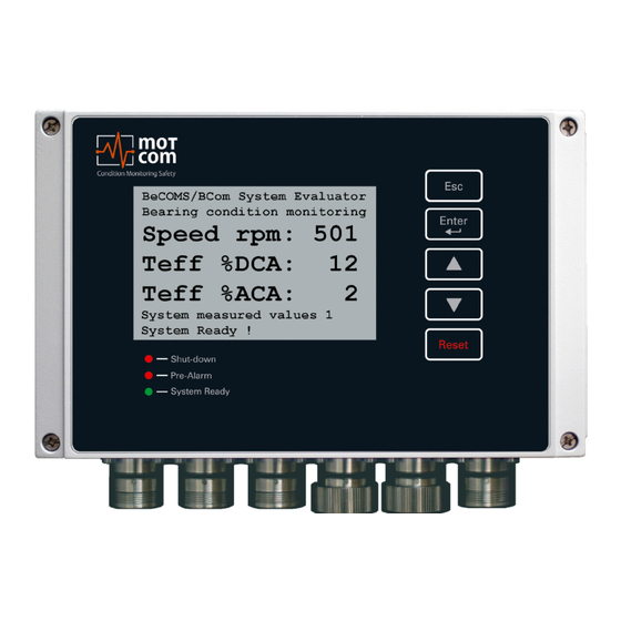
BeCOMS® | BCom User Manual 1.1.3. BCom System Components 1.1.3.1 BCom Evaluator Fig. 1.8. BCom Evaluator The Evaluator consists of a metallic case, a liquid crystal display (LCD), three LEDs (Shut-down, Pre-Alarm, System Ready), four control keys ( ) and one reset button... - Page 15 Note: Firmware updates for the Evaluator will be available and may be applied to your system only by service technicians approved by motcom GmbH. Firmware updates are free of charge. Please contact motcom GmbH or an authorized representative for details and further information.
- Page 16 BeCOMS® | BCom User Manual Fig. 1.9. Evaluator dimensions For the exact dimensions, please see under 8.3 Drawings Page 1.8 Release 130301 (revision 190211)
-
Page 17: Connectors And Pin-Out Of The Bcom Evaluator
BeCOMS® | BCom User Manual 1.1.3.2. Connectors and pin-out of the BCom Evaluator Connection at the Connectors of the Evaluator Power Serial Data Relays Reserved Reserved Supply Link +24V 1st Alarm TxD / 232 SRE-1 (brown) Relay NO 1st Alarm... - Page 18 Info: The shaft and the mounting fl ange are determined, designed and manufactured by motcom GmbH or by its authorized partners for each engine type. Only in this case correct operation and trouble-free transmission of measurement signals are guaranteed.
-
Page 19: Technical Data Of Bcom Slip Ring Encoder And Evaluator
BeCOMS® | BCom User Manual 1.1.3.4. Technical Data of BCom Slip Ring Encoder and Evaluator Power Supply: 24V DC +30/-25% Operating Current: max. 1.5 A Sensitivity: Adjustable in 5 steps Relay-Outputs: Contact load for all relays: max. 60V AC, 1A, 60VA / max. 60V DC, 1A, 60W... -
Page 20: Editions Of Bcom System
BeCOMS® | BCom User Manual 1.1.4. Editions of BCom System Features Professional Advanced Basic x = included o = optional - = not included Hardware Power Supply 24V DC +30/-25% Sensitivity adjustable in 5 Steps 2 alarm relays, Function programmable... -
Page 21: Versions Of Bcom System
Daily or Hourly Log File Display Standard Data of Log Files by Data_Indicator software Display Enhanced Data of Log Files for Damage Localization by Data_Indicator software Possibility to analyse the Log Files with optional motcom analysis Software Table 1.3. Versions Page 1.13 Release... - Page 22 The use of a computer with the BCom is only permitted when it is installed and configured by motcom GmbH or by its authorized representatives. motcom GmbH can only provide technical support if motcom GmbH approved equipment, i.e. interface converter, plugs, etc., is used.
-
Page 23: Installation
2.1. General Installation and commissioning of BCom is conducted or supervised by personnel from motcom GmbH or its authorized representatives. The installation procedure includes training for the site operation personnel. The commissioning data will be stored on the backup CD for later reference. -
Page 24: Installation Position
BeCOMS® | BCom User Manual 2.2. Installation Position Fig. 2.1. Installation position The BCom Slip Ring Encoder is installed at the end of the crankshaft of the combustion engine. The evaluator can be installed in the engine room near the engine or, alternatively, in the engine control room. -
Page 25: Sre Mechanical Adjustments
This involves positioning the engine at the firing TDC (see chapter 3.2.) at No. 1 cylinder and finding incremental encoder impulse offset (at four-stroke engine Inlet and Outlet valves are closed). The BCom SRE may only be replaced by personnel of motcom GmbH or by its authorized representatives. Page 2.3... -
Page 26: Wiring Diagram
BeCOMS® | BCom User Manual 2.4. Wiring Diagram Fig. 2.2. Principle connection The cable types for power supply, relay output, data link and connection of the SRE sensor are shown in Fig. 2.2. Principle Connections. For connector details please refer to chapters 1.1.3.2. on page 1.9 and 8.2 on page 8.6. -
Page 27: Software Installation (Optional)
Note: BCom Data_Logger and Data_Indicator installation steps are not described in this manual to avoid any unauthorized attempt to reinstall it. If necessary, please contact motcom GmbH or its authorized representatives for further information. Page 2.5 Release 130301 (revision 190211) -
Page 28: Pc Requirements (Optional)
• Display resolution 1280 x 1024 or higher ** **) depending on how many BCom-applications running parallel on the same PC As a personal computer is usually not equipped with a RS485 interface, motcom GmbH provides optionally either the necessary converter, incl. power supply equipment, to convert the RS485 signal of the BCom Evaluator into the required RS232 PC-signal (see Fig. -
Page 29: Commissioning
BeCOMS® | BCom User Manual 3. Commissioning 3.1. Pre-Commissioning Checks Check for the following: 1. correct wiring as given in chapter 1.1.3.2 and chapter 2.4. 2. correct power supply on BCom Evaluator 3. BCom Evaluator display is on 4a. correct power supply on RS-485 converter 5a. -
Page 30: Syncronization Of The Bcom Sensor With The Firing Tdc Of The First Cylinder
BeCOMS® | BCom User Manual 3.2. Syncronization of the BCom Sensor with the firing TDC of the first cylinder At the installation of BCom sensor a one time calibration of the incremental encoder has to be performed. This involves synchronising the neutral point of the incremental encoder with the firing Top Dead Center (TDC) of cylinder 1 by finding offset between them. -
Page 31: Data Sampling
BeCOMS® | BCom User Manual 3.3. Data Sampling As soon as BCom Evaluator is powered up, it starts the initial self check procedure and shows the READY status if all pre-set conditions are fulfilled. This self check procedure is carried out in a certain cycle. -
Page 32: Alarm Setting And Triggering
BeCOMS® | BCom User Manual 3.4. Alarm Setting and Triggering There are 3 alarm relays integrated in the BCom Evaluator: • 1 Alarm relay: always assigned to main alarm, aditionally programmable as pre- alarm or over speed alarm • 2... - Page 33 BeCOMS® | BCom User Manual By selecting the appropriate sensitivity level, the operator defines up to which extend he would allow moving parts to be affected by friction. With this information of fault on early stage, the operator is aware of the progressing problem and has enough time for making decisions on engine maintenance and repair.
-
Page 34: Alarm Resetting
BeCOMS® | BCom User Manual 3.4.1. Alarm Resetting • In case of a Pre-Alarm triggered: If the conditions for a Pre-alarm are not confirmed after pre-set time period, the Pre-Alarm will be reset automatically by the system. • In case of a Main-Alarm triggered: The Main Alarm will not be reset automatically by the system even after the conditions that led to it are not met any more. -
Page 35: Settings & Parameters / Using The Evaluator
BeCOMS® | BCom User Manual 3.5. Settings & Parameters / Using the Evaluator 3.5.1. Basic Usage of the Evaluator The Evaluator has an LC-display with the resolution 240x128, five control buttons and three LEDs that indicate the current system status. -
Page 36: Menu Structure
BeCOMS® | BCom User Manual 3.6. Menu structure 3.6.1. System measured values 1 (Default screen) Fig. 3.3.BCom system measured values, default screen Shows the current BCom measured values for the connected SRE sensor: Speed rpm: - engine rotation speed in RPM... -
Page 37: Graphic Overview
BeCOMS® | BCom User Manual 3.6.3 Graphic overview Displays the current measured values as a bar diagram. 3.6.3.1. BCom graphical data indicator Fig. 3.5. BCom graphical data indicator The displayed bars are: - engine rotation speed in RPM Teff %ACA... -
Page 38: Parameter Setup
BeCOMS® | BCom User Manual TS1: - the value at the analog/digital converter of the first thermovoltage measurement channel TS2: - the value at the analog/digital converter of the second t hermovoltage measurement channel TDC: - the calculated indicator of TDC (Top Dead Center) of the cylinder 1. - Page 39 BeCOMS® | BCom User Manual 3.6.5.1.1. TS Alm-Level DC: The value of DC main alarm level in the range of 0 to 5. The higher the value, the less sensitive is the system. The 0 value disables the DC alarm.
- Page 40 BeCOMS® | BCom User Manual 3.6.5.1.2. TS PreAlm-Level: The value of DC pre-alarm level in percents of DC main alarm. Possible values: 40 to 100. 3.6.5.1.3. RPM Alarm-Level: The value of overspeed alarm in RPM. Possible values: 0 to 3000, step 50.
- Page 41 BeCOMS® | BCom User Manual 3.6.5.1.11. PIN Impuls Offs.: PIN for impulse offset setup, the procedure is the same as described in chapter 3.6.5.2.5 3.6.5.1.12. TSeff ena for DC: Enable or disable (values 1 and 0 accordingly) calculating effective value of thermosignal in percents of DC alarm level.
- Page 42 BeCOMS® | BCom User Manual 3.6.5.2.5. PIN for Setup: PIN for enabling write access to menu items in “Setup Parameter”, “Setup CPU” and “Test Features”. Fig. 3.10. BCom PIN for setup To enter PIN: press [Enter], the PIN field becomes highlighted. Use [▲] and [▼] buttons to increase or decrease the value.
- Page 43 BeCOMS® | BCom User Manual 3.6.5.3.4. Testsignal A: Switch the test signal on channel A ON and OFF. At the same time the values TS1 and TS2 are displayed (signals from the first and the second thermovoltage measurement channels).
-
Page 44: Bcom Logger Measurement Data Storage And Management (Optional)
BeCOMS® | BCom User Manual 3.7. BCom Data_Logger measurement data storage and management (optional) BCom Data_Logger is a PC program for displaying and storing the measured data. Info: For detailed information on BCom Logger software please refer to BCom Data_ Logger user manual. -
Page 45: Compressing Data Files
BeCOMS® | BCom User Manual 3.7.1. Compressing Data Files To compress daily data files with the file extension *.log to *.rar * symbolizes the name of the data file, which is usually given systematically as follows: YYYYMMDD_EngineXXX, i.e. 20050331_EngineXXX, whereas YYYY: year, i.e. - Page 46 BeCOMS® | BCom User Manual Remarks: Standard settings of the application software “WinRAR” to compress the data files may not be modified: 1) Archive format: RAR 2) Update mode: Add and update files 3) Archiving option: no tag selected...
-
Page 47: Capturing The Graphic Screens
BeCOMS® | BCom User Manual 3.7.2. Capturing the Graphic Screens To capture and archive the window screens with the graphical trends of the BCom signals in daily graphic files with the file extension *.doc using “MS-Word” proceed as follows: A) Preparing/creating a new daily screen file with the file extension *.doc... -
Page 48: Archiving The Compressed Files
BeCOMS® | BCom User Manual 3.7.3. Archiving the Compressed Files To move the compressed data-files *.rar from the daily directory to the monthly archive directory or other storage media (D:\Archive_monthly_data YY.MM, whereas MM: month, i.e. 03; YY: year, i.e. 05,) proceed as follows: 1) Select all the data-files *.rar to be moved by marking the first data-files *.rar... -
Page 49: Manual Data Analysis For Compartment Localization
If no such trained person is available, or if he or she was not able to find the problem, please contact motcom GmbH or its representatives for further analysis of your measurement data. Attention: Please do not send the log file immediately in your first email to us. - Page 50 BeCOMS® | BCom User Manual Page 3.22 Release 130301 (revision 190211)
-
Page 51: Performance / Maintenance Tests
BeCOMS® | BCom User Manual 4. Performance / Maintenance Tests 4.1. Function Test During operation BCom transmits test signals to the crankshaft at regular intervals. These signals are displayed depending on the operating state: 1. if the engine runs its crankshaft is electrically isolated from bearings with the lubrication oil film. - Page 52 BeCOMS® | BCom User Manual Page 4.2 Release 130301 (revision 190211)
-
Page 53: Troubleshooting
BeCOMS® | BCom User Manual 5. Troubleshooting CAUTION The manufacturer’s warranty will become void if • the BCom Evaluator was modified without permission or • the BCom Slip Ring Encoder was opened! 5.1. During Software Installation The BCom Data_Logger and Data_Indicator software is designed and tested to run under the following Microsoft operating systems: •... -
Page 54: During Software Use
The operators should use the technical acceptable standards to trace the cause of the errors reported and skillfully fix the problem. If the problem cannot be solved, please contact motcom GmbH authorized representatives. Fig. 5.2. Example of messages displayed in the event window / status window Page 5.2... -
Page 55: Missing Control Signal
2) If this can not solve the problem, please check the error message reported and contact motcom GmbH or its authorized representatives. 2. If the green READY LED of the BCom Evaluator is on, but only the thermo... -
Page 56: Very Low / Strong Signal On Polar Diagram
BeCOMS® | BCom User Manual 5.4. Very low / strong signal on polar diagram The bearing monitoring by a BCom sensor is a relative measurement. The recording and interpretation of the signals over a longer period is important. Changes of the signal could be evaluated based on the previous recorded data. -
Page 57: Error Code And Error Description
BeCOMS® | BCom User Manual 5.5. Error code and Error description The following messages displayed on the LCD screen of the BCom Evaluator are possible. System Ready! Standard message indicating that the system works and all measured values are in the permitted range. - Page 58 BeCOMS® | BCom User Manual Single codes Table 5.1. Code combinations Page 5.6 Release 130301 (revision 190211)
-
Page 59: Repair
Based on experience, many failures can be cleared easily by fault diagnostics on site. In most cases a repair is not necessary. Dismounting may only be performed on demand by motcom GmbH or its authorized service representatives. A repair of BCom components is done exclusively by motcom GmbH. Defective parts should be sent to motcom GmbH including detailed failure description. - Page 60 BeCOMS® | BCom User Manual Page 6.2 Release 130301 (revision 190211)
-
Page 61: Spare Parts
BeCOMS® | BCom User Manual 7. Spare Parts Only the original parts supplied and approved by motcom GmbH should be used; otherwise a proper working system could not be assured. 7.1 Main Spare Parts Part No. 1 010 00 20000 Fig. -
Page 62: Accessories
BeCOMS® | BCom User Manual 7.2. Accessories Part No. 9 100 20 00000 Fig. 7.4. RS-232 Connection cable for PC to external RS-485 converter Part No. 9 200 04 22000 Fig. 7.5. 2 x 2 twisted pair communication cable Page 7.2... - Page 63 BeCOMS® | BCom User Manual Part No. 9 200 02 00000 Fig. 7.6. 2 core power cable Part No. 9 200 12 00000 Fig. 7.7. 12 core communication cable Part No. 9 301 09 10000 Fig. 7.8. Sub-D9 connector Page 7.3...
- Page 64 BeCOMS® | BCom User Manual Part No. 9 300 06 10000 Fig. 7.9. 6-pol. female connector Part No. 9 300 12 10000 Fig. 7.10. 12-pol. female connector Part No. 9 300 12 20000 Fig. 7.11. 12-pol. male connector Page 7.4...
- Page 65 BeCOMS® | BCom User Manual Part No. 9 100 30 00000 Fig. 7.12. RS-485 converter Part No. 9 110 40 00000 Fig. 7.13. Power supply unit 24V/24W Mounting position for • Part No 9 100 30 00000 • Part No 9 110 40 00000 on horizontal DIN rail NS 35 in acc.
- Page 66 BeCOMS® | BCom User Manual Part No. 9 100 40 00000 Fig. 7.14. RS 485 converter Advantec PCI Card 1602B for mounting inside PC Part No. 9 100 40 00010 Fig. 7.15. RS 485 converter PCI Card EX42062IS for mounting...
- Page 67 BeCOMS® | BCom User Manual Part No. 1 700 10 01000 Fig. 7.17. motcom Loganalyser Software ® Page 7.7 Release 130301 (revision 190211)
- Page 68 BeCOMS® | BCom User Manual Page 7.8 Release 130301 (revision 190211)
-
Page 69: Attachments
0.25mm² and overall cable diameter of 8 to 12mm. instructions, • The recommended cable is Metrofunk 2 X 2 AWG 22, (motcom GmbH especially the Part No. 92000422000) this is used as an example to show how the cable shielding connection is made. -
Page 70: Connecting The Rs-485 Converter
BeCOMS® | BCom User Manual 8.1.2. Connecting the RS-485 converter (Part. No. 9 100 30 00000) Preparing and Connecting the Cable to the Converter (Fig. 8.2): • At the free end of the signal cable, the same wires of the twisted pair black/ brown and a red wire of the other twisted pair black/red, should be used. -
Page 71: Assembling The Plug
BeCOMS® | BCom User Manual 8.1.3. Assembling the plug (Part. No. 9 300 12 10000 and 9 300 12 20000) • Push the components over the cable starting with the adapter (Pos. 1), coupling nut (Pos. 2) and the seal/strain relief element (Pos. 3), •... -
Page 72: Connection Cable - Rs485 Pci Card To Evaluator
BeCOMS® | BCom User Manual 8.1.4. Connection Cable - RS485 PCI Card to Evaluator • Cut away the outer insulation approx. 23mm from the end of the cable Cable 12-pin Sealing and strain relief Insulation and distance sleeve Connector housing... - Page 73 BeCOMS® | BCom User Manual Enclosure cylinder Insulation and distance sleeve Fig. 8.8.Step 4 • After soldering, pull the insulation and distance relief over the wires • Pull the enclosure cylinder over the soldered wires • Finally, seize the connector housing by using the installation wrench and a flat wrench No.
-
Page 74: Wiring Diagrams
BeCOMS® | BCom User Manual 8.2. Wiring Diagrams Page 8.6 Release 130301 (revision 190211) - Page 75 BeCOMS® | BCom User Manual Page 8.7 Release 130301 (revision 190211)
- Page 76 BeCOMS® | BCom User Manual Page 8.8 Release 130301 (revision 190211)
- Page 77 BeCOMS® | BCom User Manual Page 8.9 Release 130301 (revision 190211)
- Page 78 BeCOMS® | BCom User Manual Page 8.10 Release 130301 (revision 190211)
-
Page 79: Drawings
BeCOMS® | BCom User Manual 8.3. Drawings Fig. 8.12. Slip Ring Encoder (SRE) Page 8.11 Release 130301 (revision 190211) - Page 80 BeCOMS® | BCom User Manual Fig. 8.13. Slip Ring Encoder (SRE) with throughout shaft Page 8.12 Release 130301 (revision 190211)
- Page 81 BeCOMS® | BCom User Manual Fig. 8.14. BCom Evaluator Page 8.13 Release 130301 (revision 190211)
- Page 82 BeCOMS® | BCom User Manual com GmbH Kurt-Schumacher-Str.28-30 D-66130 Saarbrücken Phone +49 (0) 681 – 8837904-0 Fax +49 (0) 681 – 8837904-19 eMail info@motcomgmbh.com Internet www.motcomgmbh.com BeCOMS is a registered Trademark in: EU, Indonesia, Norway, PR China, PR Korea, USA,...
Need help?
Do you have a question about the BeCOMS BCom and is the answer not in the manual?
Questions and answers