Advertisement
Quick Links
Document number : THCR06-M04
Revised number : Rev. 04
Date : 2015. 07. 17
Manufactured by TaeHwan Automation Ind.
Operation Manual
Please carefully review the user before you use the machine.
You should fully understand the manual to use the machine property.
TEL: 82-32-624-3410~3 Fax: 82-32-624-3414
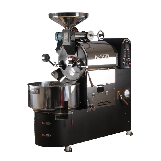
Coffee Roaster
THCR-06 (10KG)
Advertisement

Related Manuals for Proaster THCR-06


Summary of Contents for Proaster THCR-06
- Page 1 Revised number : Rev. 04 Date : 2015. 07. 17 Manufactured by TaeHwan Automation Ind. Coffee Roaster THCR-06 (10KG) Operation Manual Please carefully review the user before you use the machine. You should fully understand the manual to use the machine property.
- Page 2 Outline Ⅰ. General Information 1. Specifications 2. Purpose 3. Features Ⅱ. Safety Regulations 1. General Safety Regulations 2-1. Safety Label 2-2. Safety Device Ⅲ. Installation 1. Carriage 2. Preparation for installment 3. Installation 4. Disposal Instructions Ⅳ. Operation 1. General Information 2.
-
Page 3: Ⅰ. General Information
Ⅰ. General Information Specification HSK-NO MODEL Description Unit Q'ty THCR-06 Coffee Roaster Capacity 2~10kg/batch (MAX 10kg Green beans) Operating time About 10~15min/Batch (depending on profiles) Roaster Dimension 1,670(w)×700(L)×1,350(H)(mm) (Coffee Roaster) 1Phase V220~240 (60Hz) Power Power consumption: 2.0kw/hr, 9.1A GAS Pipe burner (18,000Kcal/hr Natural gas) Heat Source (1.5kg/hr LPG) - Page 4 1. Purpose This coffee roaster is manufactured as a commercial roaster for coffee beans - Inappropriate use of the machine (grains, foods, etc.) is prohibited. Repair of the machine must be done by a designated service center. - Carefully review safety regulations before first use and please contact the designated service center or store if you have any questions/problems.
- Page 5 5. Damages Taehwan Automation is not responsible for any damage or injury caused by: - Inappropriate use (different materials, incorrect operation) - Damages caused by self disassembly / repair - Use of the wrong voltage or gas pressure - Breakdown from improper maintenance (cleaning and general care) * We cannot guarantee coverage for damages caused by poor operation or unauthorized repair 2.
- Page 6 3) Overheating protection mechanism - The machine automatically stops when the roasting temp reaches the MAX temp to prevent overheating. The gas and power supply are stopped as well. - Do not change the setting temperature due to danger of overheating. 4) Overflowing voltage protection system (Circuit Breaker) - To prevent electrical accidents or injuries the machine is equipped with a circuit breaker that shuts off the power if necessary.
- Page 7 3. Installation * When installing an afterburner: Do not install it near a fire source! Duct made of heat- resistant material is required. Duct Work (Exhaust facility) Combustion occurs in this equipment and it should be installed in a dry place with good ventilation as close as possible to a wall so that a shorter exhaust pipe can be used.
- Page 8 1) User This machine must be operated by users who have experience with roasting coffee. Please contact your distributor or a representative of PROASTER for more information regarding training. 2) Before Operation (Precautions) Check if the outlet is connected and that the power switch at the back of the machine is switched down.
- Page 9 2. Structure and operations - Operation parts A mechanism that controls the rate and amount of hot air that is Blower guided into the drum. Speed Control flow of air from 0(close) to 5 (wide open) 1) Used to control the amount of heat inside the drum 2) Used to emit chaff &...
- Page 10 2. Structure and operations 1) Frontside product structure and nomenclature ⑴ ⑷ ⑵ ⑶ ⑸ ⑹ (16) ⒂ ⒁ ⑺ ⑻ ⑼ ⑽ ⑾ ⒀ ⑿ Input hopper Discharge handle Inlet Handle (10) Chaff drawers Damper (11) Roasting Check Window Drum (12) Cooling Tray...
- Page 11 2) Backside product structure and nomenclature ⑸ ⑴ ⑵ ⑶ ⑷ ⑹ ⑻ ⑺ Cyclone body Inspection Window Cyclone connecting piping (Back) USB Port Cooling Blower Pipe Control Box Fan Gas connection piping Exhausting Blower Weighing lever...
- Page 12 3) Control Box Product Name ⑴ ⑵ ⑶ ⑷ ⑸ ⑹ ⑺ ⑻ ⑼ Roasting timer Burner switch Air temperature Controllers Timer switch Roasting temperature Cooling Stir arm Switch Controllers Cooling Motor Switch Operation switch Emergency stop button...
- Page 13 4) Structure and name inside control box ⑴ ⑵ ⑶ ⑷ ⑹ ⑻ ⑽ ⑸ ⑾ ⑺ ⑼ ⑴ ⑺ Circuit breaker Cooling Blower ⑵ ⑻ Relay Cooling ⑶ ⑼ Inverter Burner ⑷ ⑽ Power ⑸ ⑾ Drum Control box FAN ⑹...
- Page 14 3. How to Operate Step1 After plugging in the power cord of the Roaster open the access door to the circuit breaker and flip the breaker to the ON position. (Once you turn on the circuit breaker the displays for the the temperature and timer on the control box will turn on.
- Page 15 Step2 Turn the OPERATION switch to the ON position after checking that the control box lights up. (Note: you should be able to observe a whirring sound after turning on the operation switch.) Make sure that the drum is moving and the exhaust fan is working.
- Page 16 Step4 Open the access door to the roaster body and open the gas valve inside. *Roaster internal gas valve Step5 Turn the BURNER switch to the ON position after opening all of the gas valves of the roaster (previous steps). (Turning on the burner switch causes ignition that will spark after 15 seconds and the pilot burner will be ignited)
- Page 17 Step6 Start the warm-up process by adjusting the flame. It is recommended that you preheat the drum sufficiently with low heat evenly as preheating with a strong flame may damage the drum. Please ensure that the drum is rotating before applying heat.
- Page 18 Step7 Once the machine is sufficiently warmed up and you’ve reached your optimal beginning roasting temperature you will be ready to roast. At this time place the green beans in the Hopper. Please note that some heat transfers from the roaster into the hopper and therefore you should not put the green beans into the hopper until you are ready to begin your roast.
- Page 19 Step9 Start roasting after feeding the green coffee into the drum. Note: please turn on the timer and ensure that the temperature displays are functioning. • The roast can be adjusted by the Damper which controls volume of the the exhaust air flow during roasting.
- Page 20 Step10 Once the roast is complete, turn on the cooling motor and the cooling fan before discharging roasted beans. - Cooling motor should be operating in advance to minimize the smoke generated during discharge. Step11 Ensure that the cooler and cooling motor are on and then discharge the roasted beans by open the discharging handle.
- Page 21 3. How to operate– Temp Controller and Timer <Temperature regulator> *Quoted by the manufacturer (AUTONIC) for a detailed description of the parts. (www. autonics.co.kr)
- Page 22 <Counter-CT6M-1P>...
- Page 23 Ⅴ. Cleaning and maintenance 1. Cleaning Management - Preparation Tool box, masks, work gloves, vacuum cleaner, waste beans (for removing internal dust) -Tool box will be provided when installing the product. - Prevent accidents by wearing work gloves and a mask when cleaning. - Cleaning should follow the procedure and steps set forth in this manual.
- Page 24 (2) Inside the cooler Open the access door of the cooler. Clean off the cooling motor and vacuum any fallen chaff inside the cooling tray. We recommend also using a compressor and an air gun to blow out any remaining debris.
- Page 25 2) What to clean every 50 roasts (1) Cyclone piping Step 1. Separate the clamps on both sides of the section marked with red color. (The clamps should be released one by one as the height of the cyclone is high and to avoid dropping the pipe) Step 2.
- Page 26 (2) Disassembling the Blower Step 1. Open the cap of electric line of Blower using a screwdriver. Step 2. Loosen all screws using a screwdriver to disconnect wires both on the top and at the bottom. When reconnecting the wires, you do not need to keep the sequence of the colors of wires in the original order (I.
- Page 27 Step 3. After disassembling all wires, hold the cap on the left and turn to unscrew it. The wire coming from the blower should loosen by turning upward and one from the roaster body should be loosened downward. Step 4. Picture showing wire disconnected from the roster body.
- Page 28 Step 5. Release the 4 hex bolts as indicated using a 10mm wrench after removing the clamp on the exhaust pipe. (Be careful not to lose any parts in this stage as the bolts have two parts.) Step 6. Separate the blower after loosening the 4 hex bolts and lift the blower then it will be easy to remove.
- Page 29 Step 7. This is the blower after it has been separated from the roaster. Using a screwdriver loosen the screws on the connecting pipe to the cyclone shown to the left. Please be careful not to lose any small pieces. Step 8.
- Page 30 Step 9. After removing the blower cap, loosen the nut on the center axis that holds the wing using a 17mm wrench. It will be easily loosened if you hit it lightly with a screwdriver or a small hammer after holding the nut with the wrench and holding the wing and the wrench together with one hand (as seen to the left).
- Page 31 Step 11. After loosening the bolt in the middle of the fan blades use a wrench to hold secure the fan blades and remove the headless bolts as seen to the left. Please be careful not to lose any small pieces. Step 12.
- Page 32 Step 13. After removing the fan blade use a wire brush to clean the blower cap and the inside of the blower casing. If this cleaning is not done frequently then the accumulated debris can cause noise, vibration, and a loss of performance. Step 13.
- Page 33 (3) Disassembling and cleaning the Damper Step 1. Use a 10mm wrench to loosen the 4 bolts as seen in the picture to the left. Please be careful to retain all small pieces. Step 2. Once you remove the 4 bolts you can lift and pull the damper assembly as seen in the photo.
- Page 34 Step 3. Stand the damper up as seen in the photo and loosen the bolts that are circled. Next, clean thoroughly using a brush. Any blockage in the exhaust can lead to a fire hazard. Please maintain consistently. Step 4. Once you’ve loosened the bolts and have separated the damper from the pipe clean the inside of the damper thoroughly with a...
- Page 35 Step 5. The photos to the left and below show the damper in the “0” position. You can see that even in the “0” position the damper is slightly open to allow for the minimum circulation. Step 6. Next, the photo to the left and below show the damper in the “5”...
- Page 36 (4) Removing the hopper scale Step 1. Please loosen the 4 bolts holding the hopper using a wrench. Please be careful not to lose any small pieces. Step 2. Once you have removed the hopper thoroughly clean the area below the Inlet Handle using a metal scraper or wire brush.
-
Page 37: Troubleshooting
4. Troubleshooting Issue Solution Vibrating or Knocking Clean the fan and pipes. Sound from the Fan The accumulation of debris is hampering the function of the fan. (Front) The sound may be caused by the drum touching the front cast iron plate of the roaster. - Page 38 1) Troubleshooting (1) If it is necessary to adjust the clearance between the drum and the front plate * Please note and record the gap clearance between the drum and the front plate of the original bearing before replacing the bearing or adjusting the clearance between the drum and the front plate.
- Page 39 (2) When replacing bearings Please remember to note the gap measurement before replacing the bearing. * Replacing the bearings Use a hook wrench to remove the bearing cap. To open the cap use a hook wrench on the groove of the bearing cap and hit the handle of the hook wrench with a hammer counter clockwise.
- Page 40 (3) How to reset the MD202 (when roaster ignition failed) MD202 Reset Button Step1 In case that the roaster fails to ignite, open the control box door and check if red light is lit for the MD202. Step2 If the red light is on, turn off and turn on the burner button on the front side of the control box.
- Page 41 Ⅵ. Replacement Parts List The exchange period for machines applies to new machines only. The exchange period may vary depending on how the machine was handled or the based on the conditions related to the machine and the environment of its use. Parts Exhaust Blower Output...
- Page 42 Parts Cooling Blower Output 700W 2P 18m3/min Period 4 years Parts Drum Pulley Bearing Output UCFC-208 Period 2 years Parts Drum Belt Output B type 81” 1ea Period 3~5 years...
- Page 43 Parts Front Drum Bearing Output UCSFC-207 Period 2 years Roasting Temperature Parts sensor Output Ф1.6 x 30ℓ x 1/8”x 3.0m Period 2~3 years Parts Air Temperature sensor Output Ф1.6 x 30ℓ x 1/8”x 3.0m Period 2~3 years Solenoid Valve Parts Output VE4025 2 years...
- Page 44 MD202 Parts Output Period 2 Years Sensor Arm Parts Output Period 2 Years Inverter Parts 220-230V, 50/60Hz Output Period 2 Years...
- Page 45 Ⅶ. Electronic Circuit Diagram...
-
Page 46: Equipment Maintenance
Equipment maintenance 1. Front plate, door ① Leave about 0.5m/m space between front plate and the door so that no coffee can falls between the gap. ② Fixing bolt on the front plate and washer have to be the same ones as existing ones (Otherwise, friction between the drum and the front plate might cause noise obstructing rotation of the) drum... - Page 47 3. Tension of V-Belt Hold the V-Belt down and adjust tension of A to 5~10mm (Replace the Belt if it’s broken or stretched) ② Adjust its tension by adjusting nut of motor fixing belt 4. DRUM rotation ① In case if DRUM is not properly rotating / operating - Loosen the V-Belt and turn the drum with your hand to see if it rotates smoothly - Hold down operating s/w to check the rotation condition of the Motor...
- Page 48 Ⅷ. Warranty Please read the manual. There is a charge for service visits that are not for repairing of the machine. Warranty is one year from the date of purchase. Not Vaid for following cases or second-hand machine. 1) Damage caused by natural disasters 2) Damages by poor operation or management •...
Need help?
Do you have a question about the THCR-06 and is the answer not in the manual?
Questions and answers