Table of Contents
Advertisement
Available languages
Available languages
Quick Links
FAILURE TO READ AND FOLLOW ALL INSTRUCTIONS CAREFULLY BEFORE
INSTALLING OR OPERATING THIS CONTROL COULD CAUSE PERSONAL
INJURY AND/OR PROPERTY DAMAGE.
Description ........................................................................................................................................................................ Page 1
Electrical Specifications .................................................................................................................................................... Page 1
Installation ......................................................................................................................................................................... Page 2
Wiring Diagram ................................................................................................................................................................. Page 3
Operation .......................................................................................................................................................................... Page 4
System Lockout and Diagnostic Features ......................................................................................................................... Page 5
Troubleshooting ................................................................................................................................................................. Page 5
Definition of Terms and Timing Specifications ................................................................................................................... Page 7
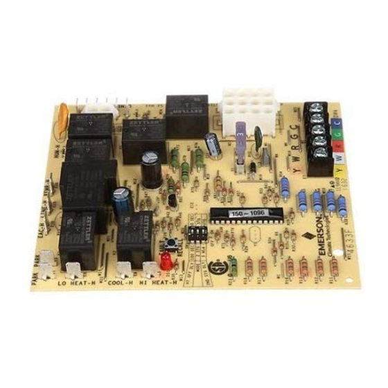
The 50M56U-801 kit is a HSI Integrated Furnace Control designed
to replace virtually all 120V Lennox HSI single stage furnace
controls using a PSC blower motor. It employs a microprocessor
to continually monitor, analyze, and control the proper operation
of the gas burner, inducer, and fan. The Kit contains:
Input Voltage
Max Input Current
Gas Valve Relay
Ignitor Relay
Inducer Relay
Circulator Relay
Circulator Relay
Humidifier Load
Electronic Air Cleaner
Minimum current to insure flame detection
Maximum current for non-detection
Maximum allowable leakage resistance
Natural, Manufactured, Mixed, Liquefied Petroleum, and LP Gas Air Mixtures are all approved for use.
Flame Establishing Time
Flame Failure Response Time
*Measured with a DC microammeter in the flame probe lead
• 50M56-801 Integrated Furnace Control
• 2 Harness Assemblies
• Control Label
• Wire Ties
• Installation Instructions
Electrical Specification [@77 deg F (25 deg C)]
Operating Temperature Range
-40° to 175°F (-40° to 80°C)
HUMIDITY RANGE:
5% to 93% relative humidity (non-condensing)
MOUNTING
Surface mount standoffs
Gases Approved
Timing Specification
white-rodgers.com
emersonclimate.com
50M56U-801
Single Stage | Direct | HSI
Integrated Furnace Control Kit
INSTALLATION INSTRUCTIONS
ELECTRICAL SPECIFICATIONS
25 VAC 60Hz
.45A @ 25 VAC
1.5 amp 0.6 PF @ 30 VAC
1.2 amp @ 120 VAC
2.8 amp @ 120 VAC
10 amp FLA @ 120 VAC
25 amp LRA @ 120 VAC
1.0 amp @ 24 VAC or 120 VAC
1.0 amp @ 120 VAC
0.25 µa DC*
0.1 µa DC*
100 M ohms
0.8 sec
2.0 sec
CONTENTS
DESCRIPTION
PART NO. 37-7616B
37-7616A
1620
Advertisement
Chapters
Table of Contents

Related Manuals for White Rodgers 50M56U-801


Summary of Contents for White Rodgers 50M56U-801
-
Page 1: Table Of Contents
Troubleshooting ................................. Page 5 Definition of Terms and Timing Specifications ........................Page 7 DESCRIPTION The 50M56U-801 kit is a HSI Integrated Furnace Control designed • 50M56-801 Integrated Furnace Control to replace virtually all 120V Lennox HSI single stage furnace • 2 Harness Assemblies controls using a PSC blower motor. -
Page 2: Installation
INSTALLATION OEM REPLACEMENT INSTRUCTIONS - 50M56U-801 WARNING Lennox Model NOTE: Ignitor must be replaced with Furnace using 120V Ignitor Failure to comply with the following warnings could control: (Recommend 21D64-2) 75M21 Ignitor result in personal injury or property damage. - Remove existing control and verify... -
Page 3: Wiring Diagram
WIRING DIAGRAM... -
Page 4: Operation
OPERATION HEAT MODE Heat ON Ignitor Ignition Blower Off Delay* Heating until Pre-Purge Warm up Activation Post-Purge Delay* Selectable Thermostat (15 seconds) (17-19 Period (25 seconds) 60/90/120/180 (30/45 Satisfied Seconds) (<3s) Seconds seconds) Thermostat Inducer Pressure Switch Ignitor Gas (MV) Flame Sensor Blower Motor Humidifier (120V) -
Page 5: System Lockout And Diagnostic Features
Release the switch and the LED will turn off for 2 seconds • If the fuse does not correct the condition, REPLACE indicating that the codes are erased. the entire 50M56U-801 control. There are no other user • After 2 seconds, the LED will turn on to indicate return serviceable parts. - Page 6 TROUBLESHOOTING Green Amber Error/Condition Comments/Troubleshooting Flash Flash Flash Below flash codes shall NOT be stored Open Flame Rollout Switch - Verify continuity through rollout switch circuit. Refer or fuse to wiring diagram terminals, RO IN / RO OUT. - Verify continuity of fuse which protects the low voltage Transformer from damage if the output is short-circuited.
- Page 7 DEFINITION OF TERMS & TIMING SPECIFICATION Term Location Definition Value INPUT – low voltage thermostat Y terminal (or equivalent) 24 VAC Terminal INPUT – low voltage thermostat W terminal (or equivalent) 24 VAC block with OUTPUT – low voltage thermostat R terminal (or equivalent) 24 VAC captive INPUT –...
- Page 8 DEFINITION OF TERMS & TIMING SPECIFICATION Term Location Definition Value Time intended to allow for the dissipation of any unburned Pre-purge Time gas or residual products of combustion at the beginning of 15 sec a furnace operating cycle prior to initiating ignition. Adaptive algorithm that adjusts the duration of ignitor warm-up for the purpose of extending ignitor life.
- Page 9 Dépannage ................................................Page 5 Définition des termes utilisés et paramètres de synchronisation................................Page 7 DESCRIPTION La trousse 50M56U-801 est un contrôleur de fournaise intégré HSI conçu pour • Contrôle de fournaise intégrée 50M56-801 remplacer pratiquement tous les contrôleurs de fournaises mono-étage Lennox HSI •...
-
Page 10: Installation
INSTALLATION DIRECTIVES POUR LE REMPLACEMENT DES PIÈCES D’ORIGINE – AVERTISSEMENT 50M56U-801 Fournaise REMARQUE : L’allumeur doit être remplacé par un Toute infraction aux avertissements qui suivent peut causer des Lennox utilisant le allumeur 120 V. contrôleur : (Recommandé : 21D64-2) Allumeur 75M21 blessures ou des dommages matériels. -
Page 11: Schéma De Câblage
SCHÉMA DE CÂBLAGE... -
Page 12: Fonctionnement
FONCTIONNEMENT MODE CHAUFFAGE Délai de mise Période Chauffage Délai de mise à l’arrêt du Réchauffage de en marche du Pré-purge d’activation jusqu’au Post-purge ventilateur* l’allumeur chauffage* (15 secondes) d’allumage point de réglage (25 secondes) (17-19 secondes) au choix 60/90/120/180 (<3 s) du thermostat (30/45 secondes) secondes... -
Page 13: Dépannage
Si le remplacement du fusible ne règle pas le problème, REMPLACER • Après 2 secondes, la DEL s’allume pour indiquer le retour au statut normal. la totalité du régulateur 50M56U-801. Aucune autre pièce ne peut être • Lorsque le commutateur reste enfoncé pendant plus de 10 secondes, le entretenue par l’utilisateur. - Page 14 DÉPANNAGE DEL ambre verte clignotante rouge Erreur/Problème Commentaires/Dépannage clignotante clignotante Les codes de clignotement suivants ne seront PAS sauvegardés Interrupteur ou fusible de débordement de - Vérifier la continuité à travers le circuit du limiteur de retour de flamme. Consulter le schéma de câblage, bornes RO IN/RO OUT. la flamme ouvert - Vérifier la continuité...
- Page 15 DÉFINITION DES TERMES UTILISÉS ET PARAMÈTRES DE SYNCHRONISATION Terme Emplacement Définition Valeur ENTRÉE – borne Y basse tension du thermostat (ou l’équivalent) 24 V c.a. Borne ENTRÉE – borne W basse tension du thermostat (ou l’équivalent) 24 V c.a. bloquée à l’aide SORTIE –...
-
Page 16: Définition Des Termes Utilisés Et Paramètres De Synchronisation
DÉFINITION DES TERMES UTILISÉS ET PARAMÈTRES DE SYNCHRONISATION Terme Emplacement Définition Valeur Période de temps prévue pour permettre au gaz non brûlé et aux produits Délai de pré-purge résiduels de combustion de se dissiper au début du cycle de fonctionnement 15 s de la fournaise, avant de commander l’allumage.
Need help?
Do you have a question about the 50M56U-801 and is the answer not in the manual?
Questions and answers