Table of Contents
Advertisement
Available languages
Available languages
FAILURE TO READ AND FOLLOW ALL INSTRUCTIONS CAREFULLY
BEFORE INSTALLING OR OPERATING THIS CONTROL COULD CAUSE
PERSONAL INJURY AND/OR PROPERTY DAMAGE.
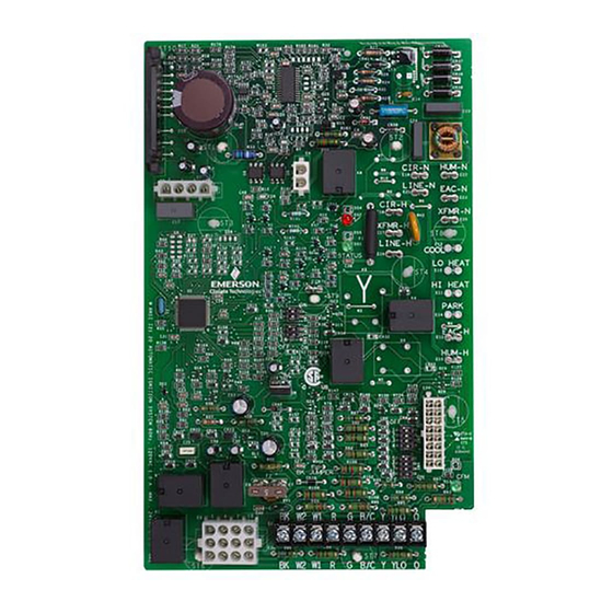
The 50V54-820 is an Integrated Furnace Control for aftermar-
ket service of Trane and American Standard Two-Stage furnace
products with variable speed blower and inducer motors. The
50V54-820 Control Board kit includes a 120V Silicon Nitride
Ignitor and can service systems with both 80V and 120V HSI
ignition and is a replacement for Trane KIT15816.
ELECTRICAL RATINGS:
Input Voltage:
25VAC, 60 Hz
Max Input Current:
@ 25 VAC 525 mA + MV
Inducer Output:
3 Phase
Relay Contact Ratings:
Gas Valve Relay: 1.5 A @ 30 VAC, 0.6 pf
Ignitor Relay: 2.0 A @ 120 VAC
Humidifier Load: 1.0 A @ 120 VAC
Electronic Air Cleaner Load: 1.0 A @ 120 VAC
Flame Current Requirements:
Min current to insure flame detection: 1.0 μA DC
Max current for non-detection: 0.1 μA DC
Max allowable leakage resistance: 100 M ohms
* Measured with a DC microammeter in series with the flame
probe lead
OPERATING TEMPERATURE RANGE:
-40° to 175°F (-40° to 80°C)
HUMIDITY RANGE:
5 to 95% relative humidity (non-condensing)
AGENCY APPROVALS:
GASES APPROVED:
Natural, Manufactured, Mixed,
Liquid Petroleum, and LP Gas Air Mixtures.
MOUNTING AND WIRING
NOTE: All wiring should be installed according to local and
national electrical codes and ordinances.
1. Disconnect electrical power and gas supply to unit, then
remove unit access panels.
2. Mark and disconnect all wires from the existing control,
then remove existing control.
3. Mount the new control board in the unit and reconnect all
the wires.
4. Units originally equipped with 80V ignitors must be
updated using the supplied 120V Ignitor and Adapter
CSA USA / Canada
white-rodgers.com
emerson.com
50V54-820
Two-Stage Integrated Furnace Control for
Furnaces with Variable Speed Blower and Inducer
INSTALLATION INSTRUCTIONS
Parts included:
• 50V54-820 Integrated Furnace Control
• 789A-820 Ignitor Kit (120V HSI Ignitor,
Mounting Bracket, 3 Screws)
• Ignitor Adapter Harness for Older 80V HSI Units
• 4 Wire Ties
• Installation Instructions
Harness. Ignitor replacement on existing 120V HSI units
is optional.
5. Verify Stage Delay, Heat Off Delay, and Blower Motor
Dipswitch settings by matching prior boards configuration
or refer to Dipswitch Configuration section of instructions
and original OEM install manual and wiring diagrams.
6. Secure any wiring with the provided cable ties as
necessary.
7. Reinstall unit access panels and reconnect electric power
and gas supply to the unit.
8. Verify unit operation by placing thermostat in heating
mode and initiating a call for heat by adjusting thermostat
5 degrees above room temperature.
DESCRIPTION
SPECIFICATIONS
CAUTION
!
Risk of Electric Shock.
Disconnect electric power
to system until installation
is complete. Do not use on
circuit exceeding specified
voltage. Higher voltage will
damage control and could
cause shock or fire hazard.
This control is not intended
for use in locations where
it may come in contact with
water.
May cause flame rollout.
Shut off main gas to heat-
ing system until installa-
tion is complete.
INSTALLATION
PART NO. 37-7667001
1725
Advertisement
Table of Contents

Subscribe to Our Youtube Channel
Related Manuals for White Rodgers 50V54-820


Summary of Contents for White Rodgers 50V54-820
- Page 1 FAILURE TO READ AND FOLLOW ALL INSTRUCTIONS CAREFULLY BEFORE INSTALLING OR OPERATING THIS CONTROL COULD CAUSE PERSONAL INJURY AND/OR PROPERTY DAMAGE. DESCRIPTION The 50V54-820 is an Integrated Furnace Control for aftermar- Parts included: ket service of Trane and American Standard Two-Stage furnace • 50V54-820 Integrated Furnace Control products with variable speed blower and inducer motors.
-
Page 2: Wiring Diagram
WIRING DIAGRAM... -
Page 3: Dip Switches
CONFIGURATION DIPSWITCHES SW3, SW4 - BLOWER MOTOR SETUP SW3-1,2 select the Outdoor Unit Size in SW1 – TIME DELAY FOR SECOND STAGE (W1/W2 Tons. Default = Off, Off JUMPERED FOR SINGLE STAGE THERMOSTAT) SW3-3,4 select the Cooling Airflow CFM. Default = Off, Off SW4-5,6 select the Cooling Airflow Delay Time SW1-1... -
Page 4: Cool Mode
OPERATION FAN MODE COOL MODE Cooling until Fan until Thermostat is Output Thermostat is Satisfied Output Satisfied Thermostat - Y2 Thermostat - Y1 Thermostat – G Compressor Blower (Fan Speed) Outdoor Fan Second Stage Blower Slow Flash First Stage Blower Slow Flash Cooling Blower On Delay = 0 sec. -
Page 5: Directives D'installation
LES DIRECTIVES AVANT L’INSTALLATION OU L’UTILISATION DE CE RÉGULATEUR PEUT CAUSER DES BLESSURES OU DES DOMMAGES MATÉRIELS. DESCRIPTION 50V54-820 est une commande de fournaise intégrée du marché des Pièces incluses : pièces de rechange pour les fournaises bi-étages Trane et American •... -
Page 6: Schéma De Câblage
SCHÉMA DE CÂBLAGE Défaut rouge/ LitePort Moteur de l’inducteur HUM N CIR N LIGNE N PAE N CIR-H XFMR N XFMR-H DEL verte de statut LIGNE-H STATUT Purificateur d’air Détecteur de électronique flamme Commutateurs DIP Humidificateur délai d’étage et délai PAE-H d’arrêt du chauffage HUM-H... - Page 7 CONFIGURATION COMMUTATEURS DIP SW3, SW4 – RÉGLAGE DU MOTEUR DU SOUFFLEUR SW3-1,2 sélectionnez la taille de l’appareil Défectuosité = SW1 – DÉLAI MINUTÉ POUR LE SECOND ÉTAGE (W1/W2 extérieur en tonnes. arrêt, arrêt CONNECTÉS POUR UN THERMOSTAT MONO-ÉTAGE) SW3-3,4 sélectionnez le débit d’air de Défectuosité...
-
Page 8: Dépannage
FONCTIONNEMENT MODE VENTILATEUR MODE CLIMATISATION Chauffage jusqu’au Réglage du thermostat Ventilateur jusqu’au Sortie atteint Sortie réglage du thermostat Thermostat – Y2 Thermostat – Y1 Thermostat – G Souffleur (vitesse du Compresseur ventilateur) Ventilateur extérieur Souffleur second étage Souffleur premier étage Clignotement lent Clignotement lent Délai de marche du souffleur de climatisation = 0 s...
Need help?
Do you have a question about the 50V54-820 and is the answer not in the manual?
Questions and answers