
Related Manuals for Matsusada DOP Series


Summary of Contents for Matsusada DOP Series
- Page 1 Instruction Manual DOP SERIES MODEL *103.9.053* B/N 103.9.053 Rev. 0.7 F-RA-001-3R1...
- Page 2 SAFETY This power supply unit generates high voltage and energy. Electric shock may lead to death or serious injury. Be sure to follow the instructions below and handle the unit with caution. 1. BE SURE TO GROUND!! Be sure to ground the power supply unit before use. 2.
- Page 3 Symbols Various symbols are used in this instruction manual and on the product for ensuring safety. What will be caused by ignoring the instructions given with the symbols or by improper handling are classified as shown below. Read carefully and understand the descriptions before proceeding to the main body of this manual.
- Page 4 Caution ! Do not install the unit upside down or Do not use the unit in a place subject to on a wrong side. high temperature or in an enclosed, Insufficient heat release may cause limited area. deterioration of parts, which may It not only hampers the unit from generate smoke or set fire.
- Page 5 First-aid procedures to be implemented in case of electrical shock RESCUE 1. Free victim from contact with live conductor quickly. Avoid contact with neither live conductor nor victim’s body. 2. Shut off high voltage at once and ground the circuit. If high voltage cannot be turned off quickly, ground the circuit to discharge, or cut high voltage line by an ax with dry wooden handle.
- Page 6 Artificial respiration PLACE VICTIM 2.Clear throat Place victim in face-upward position horizontally. CLEAR THROAT Turn head to one side quickly wipe out any fluid, mucus, or foreign body from mouth and throat with fingers. 3.Open air passage OPEN AIR PASSAGE Tilt head back and extend neck to open air passage.
- Page 7 WARRANTY 1. WARRANTY POLICY Matsusada Precision Inc. ("Matsusada") warrants that the products supplied by it will be free from defects in materials and workmanship for a period of twelve (12) months from the date of original shipment to buyer. This warranty shall not apply to any product which has been repaired, modified...
-
Page 8: Table Of Contents
Table of contents Page 1. Introduction 1 1-1 Introduction 1 1-2 Unpacking the bi-polar amplifier 1 1-3 Environmental requirements 1 1-4 Points to be careful about in handling and care 2 1-5 What to do before calling service 2 1-6 Characteristics of bi-polar amplifier 3,4... -
Page 9: 1-1 Introduction
1-1 Introduction Thank you very much for your purchase of our product. DOP series is a rack-mount four-quadrant fast response bi-polar power supply. We have done our best for the quality control of our products. Please handle this unit properly according to this instruction manual so that you can use the full performance of this unit safely for long. -
Page 10: 1-4 Points To Be Careful About In Handling And Care
1 Introduction 1-4 Points to be careful about in handling and care WHEN TOUCHING LOAD AFTER TURNING OFF THE OUTPUT Make the setting of an output voltage to zero (0). Turn off the OUTPUT ON/OFF switch. Check and confirm that the voltage is zero at an output voltmeter of this unit. Turn off the POWER ON/OFF switch. - Page 11 1 Introduction 1-6 Characteristics of bi-polar amplifier Capacitive load Capacitive load may cause oscillation when it is more than 100pF. In such case, insert 1Ω (10μF)~1kΩ(1000pF)power resistance in series with the output. Be careful that the frequency bandwidth is limited depending on the resistance inserted in series in series and the capacity under capacitive load.
-
Page 12: 1-7 Connection Precaution
1 Introduction Rising time (Stepping time):The responsivity is sometimes expressed by the rising time(as shown in the drawing below). The rising time of a bi-polar amplifier at a response speed of (=frequency bandwidth) Fc(Hz) is generally acquired by “trap proximately 0.35/fc” Falling time tf is the same as tr. -
Page 13: 2 Exterior View Diagram
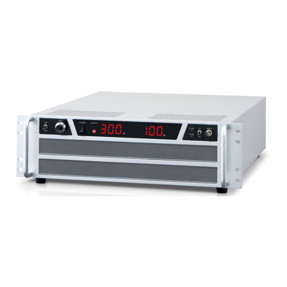
2 Exterior view diagram 2 Exterior view diagram 2-1 Front panel (~350W(Io≦30A) type) (Io:Rated output current, Vo:Rated output voltage) ① ② ③ ④ ⑤ ⑥ ⑦ ⑧ ⑨ ⑩ ⑪ ① Bias ON/OFF switch ② Bias setting dial ③ POWER ON/OFF switch ④... - Page 14 2 Exterior view diagram 2-3 Front panel (300W(60A≦Io<80A) ・600~720W(Vo<120V)type) ① ② ⑥ ⑦ ④ ⑤ ⑧ ③ ⑨ ⑩ ⑪ ① Bias ON/OFF switch ② Bias setting dial ③ POWER ON/OFF switch ④ OUTPUT indication LED ⑤ OUTPUT ON/OFF switch ⑥...
-
Page 15: 2-5 Rear Panel (600~720W(Vo<120V And 60A≦Io<80A) Type)
2 Exterior view diagram 2-5 Rear panel (300~720W(Vo<120V and 60A≦Io<80A) type) ⑤ ⑥ ⑦ INTERLOCK REMOTE ON/OFF INPUT AC200-240V ① ③ ② ④ ① Output terminal ② Voltage monitor terminal ③ Current monitor terminal ④ AC input terminal ⑤ Connector for Master-slave (option) (*300W type is 100-120VAC)... -
Page 16: 2-7 Rear Panel (600~720W(120V≦Vo)Type)
2 Exterior view diagram 2-7 Rear panel (600~720W(120V≦Vo)type) ① INTERLOCK ② REMOTE ON/OFF ③ INPUT AC200-240V ⑤ ⑦ ④ ⑥ ① Output terminal ② Voltage monitor terminal ③ Current monitor terminal ④ Inter lock ⑤ Remote switch ON/OFF ⑥ Connector for Master-slave (option) ⑦... -
Page 17: 2-8 Rear Panel (1.2Kw・2Kw(Io<80A)Type)
2 Exterior view diagram 2-8 Rear panel (1.2kW・2kW(Io<80A)type) ① INTERLOCK ② REMOTE ON/OFF ③ INPUT AC200-240V ④ ⑤ ⑥ ⑦ ① Output terminal ② Voltage monitor terminal ③ Current monitor terminal ④ Inter lock ⑤ Remote switch ON/OFF ⑥ Connector for Master-slave (option) ⑦... -
Page 18: 2-9 Rear Panel (80A≦Io Type)
2 Exterior view diagram 2-9 Rear panel (80A≦Io type) ① INTERLOCK ② REMOTE ON/OFF ③ INPUT AC200-240V ④ ⑤ ⑥ ⑦ ① Output terminal ② Voltage monitor terminal ③ Current monitor terminal ④ Inter lock ⑤ Remote switch ON/OFF ⑥ Connector for Master-slave (option) ⑦... -
Page 19: 3 Instruction For Handling
3 Instruction for handling 3 Instruction for handling 3-1 Overview This product is bi-polar amplifier that operate on constant voltage mode when set as constant voltage control, and operate constant current mode when set as constant current control, following input control voltage waveform. 3-2... -
Page 20: 3-4 Operations
3 Instruction for handling 3-4 Operations 1. To ensure your safety during installation, always be sure to connect the chassis of the unit to a ground. 2. Turn the power switch to the ON position. Digital display lights up. 3. Turn the OUTPUT ON/OFF switch to the ON position. The red indicator will light up to indicate that the bipolar amplifier is ready for operation. -
Page 21: 3-7 Remote Sensing
3 Instruction for handling 3-7 Remote sensing +S and –S shall be connected with output terminal (+sense → +OUTPUT terminal , -sense → -OUTPUT terminal) when remote sense function is not used or when unit is connected in CAUTION parallel or series. If unit is operated without +sense and –sense connected with output terminal, it can cause failure. -
Page 22: 3-8 Other Features
3 Instruction for handling 3-8 Other features a) Over Voltage Protection (O.V.P) This unit has incorporated a protection against over voltage. Even at the time of abnormality, it is limited at approx. 120% of the maximum rated voltage, protecting power supply and load against damages. b) Over Current Protection (O.C.P) This unit has incorporated a protection against over current. -
Page 23: 3-10 Output Range
3 Instruction for handling 3-10 Output Range This amplifier is operatable in four-quadrant output range (unipolar type is operated in two-quadrant range), but when operated in DC mode or in low frequency operated please derate the output as per the following diagram. Rated output voltage Rated output current AC Operating (frequency 50Hz and over/duty 50% and DC bias) -
Page 24: 3-11 Remote On/Off Switch
3 Instruction for handling 3-11 Remote ON/OFF switch The output can be turned on and off with remote switch. 〈CONNECTION DIAGRAM〉 Terminal for remote switch Remote switch switch Action with switch REMOTE SWITCH ACTION Short …… Output ON Open …… Output OFF Remote switch action by open collector. -
Page 25: 3-12 Inter Lock
3 Instruction for handling 3-12 Inter lock The output can be turned off with inter lock. For safety reason, once cut off, inter lock cannot be used to resume the operation. Turn off the HV switch to reset the condition. 〈CONNECTION DIAGRAM〉... -
Page 26: 4 Optional Features
4 Optional Features 4 Optional Features 4-1 Cancel power outage protection (LN) Power outage protection is installed in standard (see.3-8-c), but this function can be cancelled with this option, which enable you turn on and off power supply by AC input on and off. 4-2... -
Page 27: 4-6 Output Current Limit (Lcc)
4 Optional Features 4-6 Output current limit (LCc) Variable from 0 to approx 110% with Output current limiter in front panel. Set the following procedure. 1. Turn off the power, wait one minute, open the load, and short the output terminal + and -. Wire for short circuit referring to "3-2 Connection of to the load", prepare the wire of sufficient thickness to flow 110% of rated output current. -
Page 28: 5 Lms Option Instruction Manual
5 LMs option Instruction Manual 5 LMs option Instruction Manual 5-1 LMs option LMs option enables parallel operation by at most 3 to use Master-slave connection cable (LMs cable). Master unit (LMsm): It functions as a master unit at the time of parallel operation. Control voltage and Remote switch and so on, everything are controlled by master unit. -
Page 29: 5-4 Application Consideration
5 LMs option Instruction Manual 5-3 How to use ① Make sure input cable and Master-slave cable are connected. ② When LVc or LCc option is attached, be sure to use after OVP and OCP volume of slave set to counterclockwise maximum.
Need help?
Do you have a question about the DOP Series and is the answer not in the manual?
Questions and answers