Table of Contents
Advertisement
Quick Links
Advertisement
Table of Contents

Subscribe to Our Youtube Channel
Related Manuals for HBK 2755


Summary of Contents for HBK 2755
- Page 1 USER MANUAL HBK 2755 Smart Power Amplifier BE 1916 – 11 English...
- Page 3 HBK 2755 Smart Power Amplifier User Manual BE 1916 – 11 www.bksv.com March 2022...
- Page 4 HEALTH AND SAFETY CONSIDERATIONS Risks and Hazards This apparatus has been designed and tested in accordance Explosion Hazards with IEC/EN 61010 – 1 ANSI/UL 61010 – 1 Safety Danger: The apparatus is not designed to be used Requirements for Electrical Equipment for Measurement, in potentially explosive environments.
- Page 5 If the any discarded equipment or batteries marked provided plug does not fit into your outlet, there may be with that symbol a fault with the power cable provided – contact HBK. • Waste electrical and electronic equipment or •...
- Page 6 HBK or the owner of such of the most recently issued applicable regulations, standards trademark.
-
Page 7: Table Of Contents
Contents CHAPTER 1 Overview ..................................1 About this Manual..........................1 Important Safety Instructions ......................1 About the Amplifier........................... 1 Documentation..........................2 CHAPTER 2 Description ................................3 Front Panel ............................3 Display Overview ..........................5 Rear Panel ............................9 Side Panel............................10 CHAPTER 3 Installation................................ - Page 8 CHAPTER 6 Specifications ................................. 41 INDEX................................47...
-
Page 9: Chapter 1 Overview
Before using your amplifier, carefully read through the Health and Safety Considerations at the beginning of the manual. HBK provides a mains cable with IEC connector for the amplifier's mains socket and a moulded mains plug on the other end. The mains plug will be appropriate for the country where the amplifier was ordered. -
Page 10: Documentation
Additional settings are available through the menu on the display, and with HBK 2755 via Wi-Fi using a connected device. All settings can be saved and loaded as presets. -
Page 11: Chapter 2 Description
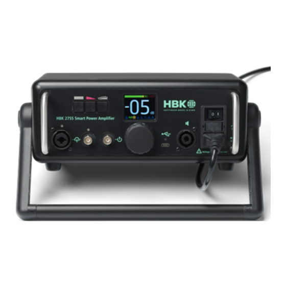
Chapter 2 Description Front Panel The figure below shows all control, display and connector functions. See the table for descriptions. Fig.2.1 Overview of the front panel 220033 ✐ Please note: Most of the front panel functions described below depend on menu settings that are volatile and will return to their default values upon switching on the amplifier. - Page 12 HBK 2755 Smart Power Amplifier – User Manual OPERATION NUMBER COMPONENT DESCRIPTION INSTRUCTION Generator button Toggles white noise (in 4292-L mode) or LF noise (in See section 4.8 4250 VVS mode) on and off. When active, the indicator above the button...
-
Page 13: Display Overview
CHAPTER 2 Description OPERATION NUMBER COMPONENT DESCRIPTION INSTRUCTION † USB-C connector Audio interface to the host computer . The USB See section 4.6 indicator above the socket illuminates when the interface is active. When connected to the PC, the amplifier turns into a ‘power sound device’ with 6) and 7) providing versatile audio inputs and 8) and 11) providing versatile audio outputs Output signal (Neutrik... - Page 14 HBK 2755 Smart Power Amplifier – User Manual MORE NUMBER SYMBOL MEANING DESCRIPTION INFORMATION Attenuation locked Avoids attenuation changes due to unintentional See section 4.7.1 contact Wi-Fi mode (HBK 2755 only) Shows Wi-Fi activity (Off/Station/ See section 3.2.3 Hotspot) and section 4.9...
- Page 15 CHAPTER 2 Description 2.2.2 Menu Display Fig.2.3 Display: Menu mode. The triangle at the bottom right Presets shows there are more menu Input items Bass/Treble Output User signal Network Holding down the large selector knob on the front panel (9), opens the Menu. To toggle back to Operational mode without performing an action, hold down the selector.
- Page 16 HBK 2755 Smart Power Amplifier – User Manual Output Lock gain Enabled or Disabled See section 4.5 Output mode Bridge (high power), Dual channel, Single-ended ch.1, Single-ended ch.2, or Single-ended ch.1+2 Power compression Constant gain or Constant power Gain limit 0, –10, –20 or –30 [dB]...
-
Page 17: Rear Panel
Rear Panel The red voltage selector at the rear panel toggles between a nominal mains voltage of 230 V and 115 V. The QR code will take you to the product download page on the website (bksv.com/2755-manuals). Fig.2.4 Rear panel of the amplifier (shown: HBK 2755) HBK 2755 Smart Power Amplifier... -
Page 18: Side Panel
HBK 2755 Smart Power Amplifier – User Manual Side Panel The amplifier is equipped with a filter over the air intake. When the amplifier is used in dusty environments, while demanding high power and intensive fan operation, the air filter is imperative, however the filter reduces the fan cooling capacity somewhat. -
Page 19: Chapter 3 Installation
The warranty will not cover damage caused by connecting to the wrong type of AC mains power. HBK provides a mains cable with IEC connector for the apparatus’ mains socket and a moulded mains plug on the other end. The mains plug will be appropriate for the country where the apparatus was ordered. - Page 20 HBK 2755 Smart Power Amplifier – User Manual 3) Connect an external device (sound recorder, voltmeter, external power amplifier, etc.) to the line output connector. ✐ Please note: The line output connector delivers low-level signals, while loudspeakers or sound sources typically require high-power signal from the power output connector.
- Page 21 CHAPTER 3 Installation ⚑ Hint: The chassis is connected to the protective earth terminal of the mains cable connector as well as to all visible metal connector parts. In case of noise or hum on the BNC input due to a low impedance ground loop, use a balanced input instead.
-
Page 22: Setting Up The Amplifier Software
1) In the menu, switch on the built-in web server by going to Network > Webserver > Enabled. 2) Go to Network > Wi-Fi mode > Hotspot. When first powered-on, HBK 2755 will be in Hotspot mode with the SSID HBK2755-nnnnnn, where nnnnnn is the amplifier’s serial number. - Page 23 To view version information, go to About > Version info. This provides the serial number and all software and hardware version information. To see if a software update is available for your HBK 2755 amplifier, go to About > Software update. You can install the update via the Wi-Fi connection.
- Page 24 HBK 2755 Smart Power Amplifier – User Manual...
-
Page 25: Chapter 4 Operation
For HBK 2755 with Wi-Fi enabled (Network > Wi-Fi mode > Station or Hotspot), it will take another 5 seconds to connect to a Wi-Fi network or present itself as a hotspot. The Wi-Fi icon in the display’s status bar will either: •... -
Page 26: Menu
HBK 2755 Smart Power Amplifier – User Manual At power-up the display will appear in Operational mode. Fig.4.2 Display in Operational mode Menu Holding down the large selector knob on the front panel, opens the Menu. To toggle back to Operational mode without performing an action, hold down the selector. -
Page 27: Presets
CHAPTER 4 Operation 4.2.1 Entering Text Entering text is more elaborate, yet easy to learn. When a text field appears, you can then use the selector knob to scroll through characters. Character order is as depicted schematically in Fig.4.4. The green block denotes ‘OK’... -
Page 28: Audio Inputs
HBK 2755 Smart Power Amplifier – User Manual ⚑ Hint: Settings in a preset named ‘Startup’ (factory default or user-defined) are non-volatile. Therefore, if you want specific settings to survive a power cycle, save them in a preset with the name ‘Startup’. - Page 29 CHAPTER 4 Operation 4.4.2 Input Levels Table 4.1 Available input gains and nominal rms and maximum peak input voltages NOMINAL RMS MAXIMUM PEAK INPUT GAIN HEADROOM INPUT VOLTAGE INPUT VOLTAGE [dB] [dB] [Vrms] [Vp] 0.63 0.20 0.063 0.47 The nominal (rms) input voltage is defined as the rms input voltage at which the output power is 500 W into 4 .
- Page 30 At power-up it is reset to 0 dB. The input is equipped with an IEPE power supply, enabling the use of, for instance, an HBK CCLD microphone. IEPE power is switched off at power-up and enabled and disabled through the menu. There is an IEPE indicator above the connector on the front panel.
-
Page 31: Audio Outputs
CHAPTER 4 Operation Audio Outputs 4.5.1 Overview The amplifier is equipped with a line output and two loudspeaker power outputs that can be combined to a high-power bridge output featuring a power stabilization option. The output attenuation is set by a central knob that can be locked and limited for safety, and optionally set to fine-stepping. - Page 32 HBK 2755 Smart Power Amplifier – User Manual 4.5.2 Line Output The signal on the (line) output BNC is a basic mix of signals from: • Internal generator output 1 • USB audio output 1 (only if a USB cable is connected to a host PC) •...
- Page 33 CHAPTER 4 Operation Fig.4.9 Display showing status bar at bottom. The power compression icon is highlighted Power compression icon colour legend Colour: Greyed out Power compression compensation is set to Constant gain (default) Colour: Yellow/ Power compression Green compensation is set to Constant power and there are no issues Colour: Red Power compression...
- Page 34 HBK 2755 Smart Power Amplifier – User Manual Single-ended outputs can deliver 125 W (sine) into 4 (63 W into 8 ) and are obviously the preferred choice for lower power loudspeakers. In Single-ended mode, one speaker can be connected to pins 1+ and 2– and a second speaker to pins 1–...
-
Page 35: Audio Usb Port
CHAPTER 4 Operation Fig.4.11 Display showing status bar at bottom. The filter icon is highlighted Filter icon colour legend: Colour: Greyed out Filters set neutral Colour: Yellow/ At least one of the Bass or Treble Green filters deviates from 0 dB Audio USB Port When the amplifier USB-C socket is connected to a host PC via a USB cable (not included), it turns into a ‘power sound device’. - Page 36 HBK 2755 Smart Power Amplifier – User Manual To change the attenuation, use the selector knob. To avoid unintentional changes, for example during a measurement session, lock the gain (Output > Gain lock > Enabled). The colours of the lock icon in the display’s status bar show the lock status.
- Page 37 CHAPTER 4 Operation Table 4.3 Available attenuation limits and maximum power from internal noise generator MAXIMUM OUTPUT GAIN LIMIT POWER INTO 6 [dB] –10 –20 –30 ✐ • The set attenuation/gain limit is reset at each power-up of the amplifier Please note: •...
- Page 38 HBK 2755 Smart Power Amplifier – User Manual In situations where high-level energy spectra are more important than low distortion, it may be preferred to have the clipping border crossed and let a fraction of the signal peaks clip at the power output. This is, for instance, true for external noise signals that are normally set at high levels in sound insulation measurements.
-
Page 39: Signal Generator
(Settings > Mode). • 4292-L mode is intended for use with an omnidirectional sound source, such as HBK’s Type 4292-L • 4250 VVS mode is intended for use with an HBK volume velocity source Table 4.4 shows the relation between amplifier mode, push buttons and noise signals. - Page 40 HBK 2755 Smart Power Amplifier – User Manual Table 4.4 Signal generator standard noise signals MODE FRONT PANEL BUTTONS LEFT MIDDLE RIGHT Noise Noise Noise Type Type Type Name [Hz] [kHz] Name [Hz] [kHz] Name [Hz] [kHz] 4292-L Equalized White...
-
Page 41: Web Server
Operation Web Server With HBK 2755, you can control attenuation, the generator and the presets via Wi-Fi (remotely). To do so, switch on the built-in web server by going to Network > Webserver > Enabled. Then, connect your device (smartphone, tablet or laptop) to the amplifier in either of two ways: 1) Directly: The amplifier is set up as a hotspot (Network >... - Page 42 HBK 2755 Smart Power Amplifier – User Manual Fig.4.19 The HBK 2755 web page (not available on HBK 2755-A). The colour of device name (at the top) indicates the connection status: Red: No connection Green: Connection To start signal playback, click a generator button with the cursor. The button frames will turn red momentarily while the command is being sent to the amplifier.
- Page 43 – Click Upload to send new signals to the amplifier (in .wav format) – Click to delete the user-defined signal Fig.4.22 Other pages in the HBK 2755 web page: Right: Presets Left: Signals To playback the selected user-defined signal: 1) Click to go back to the Home page.
-
Page 44: Fans
HBK 2755 Smart Power Amplifier – User Manual 4.10 Fans To deliver the highest power available, the amplifier is equipped with a cooling fan. At a moderate ambient temperature and a low average output power, the fan stays off. At an internal heat sink temperature of 55 ºC (131 ºF), the fan speed is temperature-controlled, starting at a low speed and... -
Page 45: Maintenance, Service And Repair
Chapter 5 Maintenance, Service and Repair General Maintenance Instructions • Clean only with a dry cloth • Do not use the amplifier if the power cord is broken or frayed. • Protect the power cord, do not stand on it or pinch it, particularly at the plug and the point where it meets the housing •... -
Page 46: Protection Features
HBK 2755 Smart Power Amplifier – User Manual Protection Features The amplifier is equipped with several protection features. Should a fault condition arise, one of the protection circuits will activate. It may shut down the amplifier and show a full-screen icon on the display. -
Page 47: Replacing The Fuse
CHAPTER 5 Maintenance, Service and Repair Replacing the Fuse If the amplifier does not respond to the mains power switch, while the mains power supply seems to be okay, the fuse might be blown. Although this normally indicates a fault in the amplifier, it might be a spurious fault, and replacing the fuse might solve the problem. -
Page 48: Service
If the amplifier does not respond even after checking the above possibilities, or if another serious fault occurs, disconnect it completely and secure it against unintended operation. Contact your local HBK customer care team and give details of any errors found. - Page 49 Chapter 6 Specifications General Specifications 4 MAXIMUM OUTPUT 500 W POWER = 25 ºC, 230 V /50 Hz, 6 330 W 1 kHz, THD <10% 8 250 W CONTINUOUS OUTPUT POWER (1 kHz, 6 ) = 25 ºC with air filter 250 W = 25 ºC without air filter 330 W...
- Page 50 HBK 2755 Smart Power Amplifier – User Manual FREQUENCY RESPONSE Line Output –0.2 dB Input Gain and Attenuation (20 Hz – 20 kHz) 0 dB, from BNC Input to: Power Output 0.3 dB See also Fig.6.1 SNR (MAX POWER 1 kHz)/(SILENCE 0 – 20 kHz)
- Page 51 CHAPTER 6 Specifications Signal Generator INTERNAL STANDARD White 50 Hz – 5 kHz NOISE TYPES 4292-L Mode and Frequency Pink 50 Hz – 5 kHz Range (1/3-octave bands) Equalized (4292) 50 Hz – 5 kHz 10 Hz – 1.6 kHz 4250 VVS Mode and Frequency 20 Hz –...
- Page 52 HBK 2755 Smart Power Amplifier – User Manual User Interface CONNECTORS Input Socket Neutrik Combo Jack 3-pole XLR (balanced) and TRS ¼-in jack, 1 × differential or 2 × single-ended) Line Output Socket Power (Speaker) Output Socket Neutrik 4-pole speakON type (1 ×...
- Page 53 CHAPTER 6 Specifications Supported Products Only use accessories specified by HBK FOR ARCHITECTURAL ACOUSTICS APPLICATIONS • DIRAC Type 7841 • ½ Prepolarized, Free-field Microphone Type 4966-H-041 with CCLD preamplifier Type 1706 • OmniPower Omnidirectional Sound Source Type 4292-L FOR SOURCE PATH CONTRIBUTION (SPC) APPLICATIONS •...
- Page 54 HBK 2755 Smart Power Amplifier – User Manual Compliance with Standards The CE marking is the manufacturer's declaration that the product meets the requirements of the applicable EU directives. RCM mark indicates compliance with applicable ACMA technical standards – that is, for telecommunications, radio communications, EMC and EME.
- Page 55 Index Numerics 1-channel output ............24 Diagram, functional ............. 2 2-channel output ............25 Differential ............13 4250 VVS mode ............ 5 Display ................5 4292-L mode ..........5 Dual channel mode ............26 Accessories ..............45 Enter text ..............19 Air filter ...............37 Exit ................9 Air intake ..............10 Extension cables ............11 Amplifier mode .............6...
- Page 56 Pins ...............12 Power ................4 IEPE power ............7 Power compression ...........6 Info ................15 Power compression icon ..........25 Input icon ..............20 Power output ..............24 Input levels ..............21 Power output mode ...........26 Interrupted noise measurement .......32 Power up ..............17 Power up conditions ..........17 Presets ............
- Page 57 Webserver ..............33 White noise ............4 Unbalanced dual-channel source ......13 White-ext ..............32 Unbalanced single-channel source ......13 Wi-Fi mode ..........6 Upload .................35 Wireless LAN ..............15 USB Audio Interface ZE-0948 ........29 USB connector ..........5 User signal ............. 8 XLR input ..............7 XLR input gain ............22 XLR jack ..............4 Version info ............
- Page 60 www.bksv.com...
Need help?
Do you have a question about the 2755 and is the answer not in the manual?
Questions and answers