Outback Power Systems FX Series Installation Manual
Inverter/charger system
Hide thumbs
Also See for FX Series:
- Installation manual (60 pages) ,
- Programming manual (59 pages) ,
- Brochure (2 pages)
Table of Contents
Advertisement
Quick Links
Welcome to the OutBack Power Systems FX Series Inverter/Charger System
The FX Series Inverter/Charger off ers a complete power conversion system—DC to AC, battery
charging, and an AC Transfer Relay—and can be used for stand-alone or back-up applications.
OutBack Power Systems does everything possible to assure the components you purchase will function
properly and safely when installed as instructed according to local and national electrical codes. Please
read all of the instructions and the instructions that come with any OutBack components included in
your power system. Instructions on individual FX set-ups as well as systems assemblies are included
with the FX and VFX Series Inverter/Charger Installation Manual.
The OutBack Power Systems FX Series Inverter/Charger is ETL listed to UL1741 (Inverters, Converters,
Controllers, and Interconnection System Equipment for Use with Distributed Energy Resources). All
Mobile FX Series Inverter/Chargers are ETL listed to UL 458.
Grounding Instructions – Each FX should be connected to a grounded, permanent wiring system. For
most installations, the negative battery conductor should be bonded to the grounding system at one
(and only one) point in the DC system. All installations must comply with all national and local codes
and ordinances. System grounding as required by the National Electric Code, ANSI /NFPA 70-1996, is the
responsibility of the system installer.
The equipment ground is marked with this symbol:
The FX and VFX Series Inverter/Charger Programming Manual covers the following information:
• Safety
• Programming or "stacking" multiple FXs using the OutBack Power Systems MATE
IMPORTANT SAFETY INSTRUCTIONS
SAVE THESE INSTRUCTIONS
General Precautions:
1. Use caution whenever working around electricity, electrical components, and batteries. There is
always a potential for shocks, burns, injury, and even death if an installer or user comes in contact
with electricity.
2. Read all instructions and cautionary markings on the FX, the batteries and all appropriate sections of
this manual as well as other component manuals before using the system.
3. Be sure each FX is securely installed according to the FX and VFX Series Inverter/Charger Installation
Manual.
4. Follow all local and national electrical codes when installing OutBack equipment and components.
4
Advertisement
Chapters
Table of Contents
Troubleshooting

Related Manuals for Outback Power Systems FX Series


Summary of Contents for Outback Power Systems FX Series
- Page 1 Welcome to the OutBack Power Systems FX Series Inverter/Charger System The FX Series Inverter/Charger off ers a complete power conversion system—DC to AC, battery charging, and an AC Transfer Relay—and can be used for stand-alone or back-up applications. OutBack Power Systems does everything possible to assure the components you purchase will function properly and safely when installed as instructed according to local and national electrical codes.
- Page 2 FX MODES AND PROPERTIES Each OutBack FX Inverter/Charger comes with various default values set at the factory. Typically, a single FX installation will retain these values, but multiple FXs will require programming using the OutBack MATE. Viewing the status of an FX and adjusting its functions also requires a MATE. SETUP SCREENS MAIN-------------------------- From the MAIN screen, press...
- Page 3 SEARCH MODE An FX consumes a small amount of power when it is not actively supplying power to loads or for battery recharging. During this SEARCH MODE, the FX sends out AC pulses to sense load demands. Once a large enough load is sensed, the FX turns ON and provides AC power. Using SEARCH mode, a user can adjust the FX so it only comes ON for certain size loads and not for smaller ones.
- Page 4 Pressing returns you to the SETUP/FX/ SETUP/FX/SEARCH------------- SEARCH screen. search setup completed Pressing returns the user to the choose SETUP category screen. SETUP MAIN Pressing returns to the MAIN Menu. MAIN INPUT MENU The INPUT screens allow the user to choose either grid or generator AC input and the maximum amperage from either source that can pass through the FX before a warning occurs.
- Page 5 SETUP/FX/INPUT----------P00 To choose your AC input source in the ac transfer ac transfer control screen, press . Press DOWN GRID control to view the next screen. DOWN GRID PORT By using , the ac1/grid menu sets the maximum current the FX will allow to SETUP/FX/INPUT----------P00 be drawn from the grid by either AC loads or the ac1/grid...
- Page 6 ADVANCED SCREENS All the FX operation settings can be adjusted in the MATE’s ADVANCED screens, including some previ- ously discussed in the INPUT and SETUP menus. Changing the settings under any menu will aff ect the values in all menus. The ADVANCED screens are accessed via the password MAIN-------------------------- ADV/PASSWORD---------------- ADV/SETTINGS/WARNING...
- Page 7 INVERTER MENU The INVERTER screens allow adjusting the inverter’s operations to match the AC load and battery recharging requirements, including the search functions, low-battery cut-out, the FX’s output voltage, and resetting the FX to its factory default values. After entering the ADVANCED screens, press on the choose device screen.
- Page 8 The search pulse spacing screen adjusts the ADV/FX/INVERTER-------P00 amount of time the FX waits before producing search 60 cycles additional AC pulses to sense a load. The higher pulse spacing the number of cycles, the lower the FX power consumption, but the longer it takes before AC DOWN INC PORT loads are powered.
- Page 9 Use this screen to reset the FX to its factory ADV/FX/INVERTER------------- default set points. This will cause all previous reset FX to factory programming changes to be lost. Press MORE defaults choose the HUB port whose FX is to be reset and then press or, if no HUB is in use, press DOWN...
- Page 10 CHARGER MENU Each battery manufacturer has specifi c recharging directions and guidelines. OutBack’s default values work for many batteries, but might not be the ideal settings. The CHARGER Menu allows these settings to be adjusted. to the manufacturer’s recommendations. From the ADVANCED menu, press choose device: MATE Press...
- Page 11 The absorb time limit must be long enough for ADV/FX/CHARGER---------P00 the batteries to regain 95-100% of their charge. absorb 01.0 hrs This time limit can be set between 0 hours and 24 time limit hours using . The FX auto- matically reduces this limit when it’s connected to DOWN INC PORT...
- Page 12 An occasional equalize charge helps destratify the ADV/FX/CHARGER---------P00 batteries for a longer working life. Pressing the equalize 14.6 vdc hot key leads to screens that begin the AC IN set point EQ charging voltage. The equalize set point deter- mines the recharging voltage, which can range DOWN INC PORT between 14.0 VDC and 17.0 VDC (consult your...
- Page 13 GENERATOR MENU OutBack off -grid and mobile FX Inverter/Chargers are programmed to use an AC generator as their default source of AC input. The CHARGER GEN screens allow a user to adjust the input voltage window and time delays of thei AC input. From the ADVANCED screen, press choose device: MATE...
- Page 14 The ac/2 gen lower limit is the lowest allowable ADV/FX/GEN---------------P00 voltage for the FX to connect to the generator. ac2/gen 108 vac If the voltage falls below this limit, the FX will lower limit disconnect from the generator. This voltage value is adjusted using for values DOWN INC...
- Page 15 This feature is not operational at this time. Press ADV/FX/GEN---------------P00 to view the fi nal GEN screen. DOWN ac2/gen support DOWN OFF PORT ADV/FX/GEN-------------------- Pressing returns to the beginning of the GEN programming ADV/FX/INVERTER menu. returns to the completed ADVANCED screens and displays the MAIN MAIN screen.
- Page 16 An easy rule to remember is any FX wired to a specifi c phase or leg must be programmed to that phase. Stacking Options The FX Series Inverter/Chargers can be stacked in the following confi gurations (see page 7). 1. OutBack Parallel 2. Classic Series 3.
- Page 17 Components and Connections 1. With all AC and DC breakers OFF, connect all FXs to the HUB with individual lengths of CAT5 cable. BYPASS OUTPUT INPUT AC Breakers Off DC Breakers Off POWER MATE Port is not operable MATE connects at 1st MATE Mate Mate...
- Page 18 2. With the FXs connected to the HUB, turn only the DC breakers ON and power up the components. All AC breakers should be OFF. NOTE: For 3-phase stacking, the jumper in the HUB must be set to the 3ph position. See the HUB Communications Manager User Guide for further information.
- Page 19 3. After powering up the components, connect the MATE to the HUB. a) Plug the MATE into the 1st MATE Port on the HUB. b) The MATE will power up and should recognize any component connected to the HUB. c) The MATE can then program the FXs. d) The fi fth MATE screen (“Port Assignment”) should display all the FXs and any OutBack Charge Controllers in the system.
- Page 20 STACKING OPTIONS OutBack FXs can be stacked in one of fi ve diff erent confi gurations: 1. OutBack Parallel 2. Classic Series 3. OutBack Series 4. OutBack Series/Parallel 5. 3-Phase Note: Although stacking 10 FXs is possible, OutBack’s AC hardware only accommodates confi gurations of two, four, or eight FXs.
- Page 21 3. OutBack Series • 2-10 FXs are wired to two 120VAC output legs producing 240 VAC between them. • This system requires an FW-X240 or PSX-240 Auto Transformer. • 240VAC can be produced on one leg if the load is ten amps or less; an FX on one leg can power loads on the other leg, helping to balance loads.
- Page 22 5. 3-Phase • Three—and only three— FXs are connected, one to each of three 120 VAC output legs that produce 208 VAC between any two legs of the system. • The HUB requires a jumper between the two Slave FXs for this stacking to function (see HUB Manual).
- Page 23 2. Classic Slave • Classic Slave is the designation of the second FX in a two-inverter, split-phase system that produces 240 VAC without using an FW-X240 Auto Transformer. • This FX is plugged into Port 02 of the HUB. OB Slave L1 and OB Slave L2 designations are used in OutBack Parallel Stacking or OutBack Series/ Parallel stacking 3.
- Page 24 PROGRAMMING THE FXs Once the MATE recognizes each FX (and Charge Controller or CC), push and hold the fi rst two soft keys simultaneously to return to the MAIN menu. To program the FXs, go to the ADV/FX/STACK menu on the MATE navigating with the following steps: MAIN-------------------------- Press...
- Page 25 choose device: In the ADV menu, press MATE ADV/FX/PAGE 1----------------- choose category: On the ADV/FX/PAGE 1 screen, press go to the ADV/FX/PAGE2 screen. CHGR ADV/FX/PG2--------------------- choose category: Press which leads to the ADV/FX/PAGE3 screen. GRID ADV/FX/PAGE3------------------ choose category: On the ADV/FX/PAGE3 screen, press STACK STACK PG4...
- Page 26 ADV/FX/STACK-----------P01 stack 1-2ph Master Stacking the FX Series Inverter/Chargers begins phase on this screen. See specifi c stacking procedures in DOWN INC DEC PORT the next section. ADV/FX/STACK------------P01 Port 01 always takes the Master FX. stack 1-2ph Master phase DOWN INC...
- Page 27 1-2ph Master With the Port 01 FX as the Master, press the <PORT> soft key to change the remaining Ports and designate the remaining FXs as Slaves. The MATE screen for Port 02 will look like this: ADV/FX/STACK---------P02 The MATE is now ready to program the FX plugged stack 1-2ph Master...
- Page 28 ADV/FX/STACK------------P02 stack Slave OB Slave 1 stacking phase phase DOWN INC DEC PORT OutBack (OB) SLAVE L2 • Set the FX’s you want as series Slaves (Leg 2) to OB Slave L2. • This FX is considered the L2 phase. ADV/FX/STACK----------P02 stack Slave...
- Page 29 ADV/FX/STACK----------P01 stack 3ph Master phase The FX has now been set to 3ph Master status. DOWN INC DEC PORT 3-Phase (3-ph) Slave • Set the two Slave FX’s to 3ph Slave and make sure they are in Ports 02 and 03 of the HUB. •...
- Page 30 Depending on the model, each FX consumes 20-25 watts of power when it remains on, even if it isn’t actively inverting or charging. OutBack Power Systems off ers the option to shut down (put into Silent mode) some or all of the Slave FXs until the loads require them to come on again.
- Page 31 The default value for the power save level slave ADV/FX/STACK-----------P02 adjust only screen is 1. Press power save level adjust this value. Press to change the PORT slave adjust only value of each Slave FX. DOWN INC DEC PORT The Slave(s) must be connected to Port 2 or higher on the HUB.
- Page 32 With the programming completed, turn the AC output breakers ON with the AC BYPASS on the AC breaker panel switched to NORMAL. BYPASS OUTPUT INPUT NOTE: If you are doing OutBack Stacking, turn on the FW-X240 Auto Transformer breaker now. Otherwise, go to the next step.
- Page 33 Turn the AC input breakers BYPASS OUTPUT INPUT If the FX’s AC source is available, the yellow AC IN STATUS light will blink. The FX will connect to the utility grid when the voltage is within 108-140VAC and the frequency between 54-66 Hz. After about 30 seconds, the AC IN light should stop blinking and stay lit.
- Page 34 • The system includes only two FXs and must be set up as described here. • The bottom FX Series Inverter/Charger is plugged into Port 01 of the HUB and the next or second FX is plugged into Port 02.
- Page 35 OutBack Parallel Stacking • Four FXs in a single system are referred to as a Quad Stack. • The FX installed at the bottom of the stack is plugged into Port 1 of the HUB. • The second, third, and fourth FXs are plugged into Ports 2, 3, and 4 respectively PRESS <INC>...
- Page 36 Ranking the Slaves • Start from the last ADV/FX/STACK screen. ADV/FX/STACK----------P04 ADV/FX/STACK-----------P04 ADV/FX/STACK---------P02 stack Slave power save level power save level phase slave adjust only slave adjust only DOWN INC DEC PORT DOWN INC DEC PORT DOWN INC DEC PORT Press the <DOWN>...
- Page 37 After setting up your OutBack Parallel Stacking and establishing the Master and Slave order, shut off all the AC input and output breakers and check your system via the following MATE screens: ADV/FX/STACK---------P04 ADV/FX/STACK--------------- ADV/FX/STACK---------P04 power save level stacking setup stack OB Slave slave adjust only completed...
- Page 38 OutBack Series / Parallel Stacking OutBack Series/Parallel Stacking is a versatile confi guration for a system using between two and ten FXs with AC outputs connected to one of the two 120 VAC legs. Although it’s acceptable to divide the FXs unevenly between the two 120 VAC legs, at least one FX must be on each leg.
- Page 39 PRESS <INC> UNTIL 141, THEN PRESS ENTER MAIN------------------------- ADV/SETTINGS/WARNING ADV/PASSWORD--------------- changes made could adversely 8:25:04A enter the password aff ect system performance SUM STATUS SETUP ADV ENTER DEC EXIT ADV--------------------------- ADV/FX/PAGE 1--------------- ADV/FX/PG2----------------- choose a device: choose category: choose category: DC MATE ADV INV CHGR PG2 PG1 GRID GEN PG3...
- Page 40 ADV/FX/STACK----------P04 ADV/FX/STACK----------P04 ADV/FX/STACK---------P03 stack OB Slave L2 stack OB Slave L2 stack OB Slave L2 phase phase phase DOWN INC DEC PORT DOWN INC DEC PORT DOWN INC DEC PORT Press the <PORT> soft key again Push the <INC> soft key three until Port 04 appears on the times to set the stack phase to screen.
- Page 41 Ranking the Slaves: • From the last screen— ADV/FX/STACK P04—press the <DOWN> soft key twice to get into the power save level slave adjust only menu. This menu allows you to set the order in which the Slave FXs come “ON” •...
- Page 42 • If you have more than three Slaves, keep increasing the value in the power save level master adjust only screen and verify each Slave’s INVERTER LED comes on as expected. • This check verifi es all FX Series Inverter/Chargers are stacked correctly. • Adjust the power save level master adjust only down to 0.
- Page 43 3-Phase Stacking (Three FX Series Inverter/Chargers Only) A 3-phase stacked system with only three FXs must be set up as described here: • Turn off all AC output and AC input breakers before powering up FX’s. • Plug the top FX into Port 01 of the HUB, the 2nd FX into Port 02, and the 3rd FX into Port 03.
- Page 44 ADV/FX/STACK-----------P02 ADV/FX/STACK-----------P02 ADV/FX/STACK------------P03 Stack Master stack 1-2ph Master stack Slave phase phase phase DOWN INC DEC PORT DOWN INC DEC PORT DOWN INC DEC PORT PRESS FIVE TIMES ADV/FX/STACK-----------P03 ADV/FX/STACK----------P03 stack 1-2ph Master stack Slave phase phase DOWN INC DEC PORT DOWN INC DEC PORT Auxiliary (AUX) Functions The AUX output provides a 12VDC, 0.7ADC max output at the AUX terminals to control either DC or AC...
- Page 45 ADV/PASSWORD---------------- enter the password The screen displays 132. Press the button until it scrolls to the password 141. ENTER INC EXIT ADV/PASSWORD enter the password Push ENTER ENTER INC EXIT choose device: In the ADV menu, press MATE ADV/FX/PAGE 1----------------- choose category: On the ADV/FX/PAGE 1 screen, press go to the ADV/FX/PAGE2 screen.
- Page 46 ADV/FX/PG2------------------- choose category: Press which leads to the ADV/FX/PAGE3 screen. GRID ADV/FX/PAGE3------------------ choose category: On the ADV/FX/PAGE3 screen, press adjust the AUX output set points and operation. STACK PG4 Selecting changes ADV/FX/AUX---------------P00 the mode of the AUX. aux output AUTO •...
- Page 47 LIST OF AUX FUNCTIONS • Cool Fan activates the standard TurboFan which cools the FX during an over temperature condition. • Divert DC and Divert AC allows the AUX to divert excess renewable energy to a DC or AC load, respectively.
- Page 48 ADV/FX/AUX---------------P00 From the remote aux output function screen, aux output Remote press . This will bring up the DOWN function fi rst of several screen used to adjust which ever DOWN INC PORT mode you have chosen for the AUX function. The genalert on setpoint screen shows the ADV/FX/AUX---------------P00 voltage—whose range is between 10.0 VDC and...
- Page 49 After a battery has recharged or returned to ADV/FX/AUX----------------P00 the genalert off setpoint, genalert off delay genalert 9 min determines the amount of time the generator off delay remains on to assure the battery has been more DOWN INC PORT fully recharged.
- Page 50 MATE (see MATE User Manual). Maintenance Please contact OutBack Power Systems Technical Services for any FX repairs due to malfunctions or damage. For routine, user-approved maintenance: • Disconnect all circuit breakers and related electrical connections before doing any cleaning or adjustments.
- Page 51 12 VDC System DEFAULT MINIMUM MAXIMUM Float Voltage 13.6V Absorb Voltage 14.4V EQ Voltage 14.4V (24VDC Grit-Tie=29.2) 14V ReFloat 12.5V LBCO 10.5V LBCI 12.5V Sell RE Gen Alert Off Set Point On Set Point Load Shed Off Set Point Vent Fan ON Set Point Diversion ON Set Point 14.6V Absorb Time...
- Page 52 TWO YEAR LIMITED WARRANTY INFORMATION FX Series Inverter/Charger Products OutBack Power Systems, Inc. (“OutBack”) provides a two year (2) limited warranty (“Warranty”) against defects in materials and workmanship for its FX/VFX Series Inverter/Charger products (“Product(s)”) if installed in fi xed location applications.
- Page 53 RMA number. The sender must prepay all shipping charges to the agreed upon OutBack Power Systems location, and insure the shipment, or accept the risk of loss or damage during shipment. OutBack is not responsible for shipping damage caused by improperly packaged Products, the repairs this damage might require, or the costs of these repairs.
- Page 54 *Extended Warranty OutBack Power Systems off ers an optional three (3) year extension to the standard two (2) year Limited Warranty for the FX/VFX Series Inverter/Charger product. To request a 3-year Limited Warranty extension for a total eff ective warranty coverage period of fi ve (5) years;...
- Page 55 19009 62nd Avenue NE European Sales Offi ce Arlington, WA 98223 USA Barcelona, ESPAÑA (+1) 360.435.6030 (+34) 600.843.845 www.outbackpower.com 900-0086-01-00 REV B...
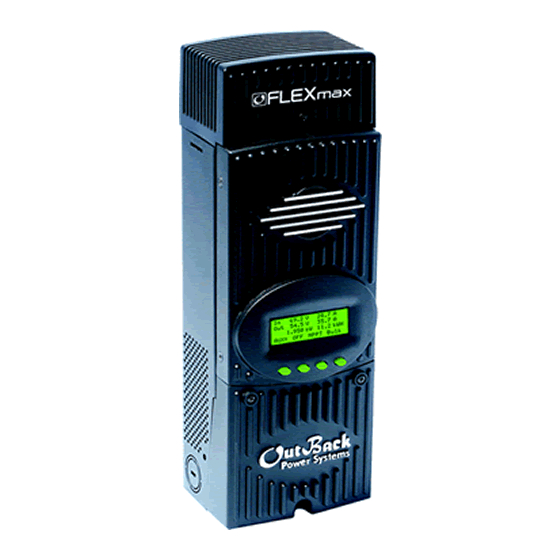
- Page 56 Maximum Power Point Tracking (MPPT) charge controllers from ability to step-down a higher voltage solar array to recharge a lower OutBack Power Systems. The innovative FLEXmax MPPT software voltage battery bank. A built-in, backlit 80 character display shows algorithm is both continuous and active, increasing your photovoltaic the current status and logged system performance data for the last array power yield up to 30% compared to non-MPPT controllers.
- Page 57 FLEXmax Specifications - FM80-150VDC - FM60-150VDC Nominal Battery Voltages 12, 24, 36, 48, or 60 VDC (Single model - selectable via 12, 24, 36, 48, or 60 VDC (Single model - selectable via field programming at start-up) field programming at start-up) Maximum Output Current 80 amps @ 104º...
- Page 58 Maximum Power Point Tracking Charge Controller User’s Manual Installation and Programming...
- Page 59 Warranty Summary Dear OutBack Customer, Thank you for your purchase of OutBack products. We make every eff ort to assure our power conversion products will give you long and reliable service for your renewable energy system. As with any manufactured device, repairs might be needed due to damage, inappropriate use, or unintentional defect.
- Page 60 The OutBack Power Systems FLEXmax 80 and FLEXmax 60 Maximum Power Point Tracking Charge Controllers are ETL listed in North America to UL1741 (Inverters, Converters, Controllers, and Interconnection System Equipment for Use with Distributed Energy Resources). It is also in compliance with European Union standards EN 61000-6-1 and EN 61000-6-3 (see page 91).
-
Page 61: Table Of Contents
TABLE OF CONTENTS SCOPE ........................................5 INTRODUCTION ....................................5 INSTALLATION GUIDELINES AND SAFETY INSTRUCTIONS ..................6 Standards and Requirements ............................6 Battery Safety ....................................7 INSTALLING THE Charge Controller ON FLEXware ENCLOSURES ..............10 OPEN CIRCUIT VOLTAGE/WIRE AND DISCONNECT SIZING ................... 10 CHARGE CONTROLLER CONNECTIONS .......................... - Page 62 Vbatt Calibration ..................................51 RTS Compensation ..................................51 Auto Restart ....................................52 Aux Polarity .....................................53 Reset to Defaults? ..................................53 (DATA) LOGGING ....................................55 Clearing Total and Daily Stats ...............................55 STATS ..........................................56 Secondary Stats Screen ................................57 MICRO-HYDRO, WIND TURBINE, AND FUEL CELL APPLICATIONS................58 ADVANCED MENU (Micro-Hydro) ...............................59 Charge Controller ABBREVIATED MENU MAP ........................60 APPLICATION NOTES ...................................61 Charge Controller EFFICIENCY vs.
-
Page 63: Scope
LCD screen. Each Charge Controller is designed to seamlessly integrate with other OutBack components and can be remotely monitored and confi gured (up to 1000 feet) by the optional OutBack Power Systems MATE display (version 4.0.4 or greater). FIRMWARE This manual covers Charge Controller fi rmware version 001.009.001... -
Page 64: Installation Guidelines And Safety Instructions
OUTBACK CHARGE CONTROLLER INSTALLATION GUIDELINES AND SAFETY INSTRUCTIONS This product is intended to be installed as part of a permanently grounded electrical system as shown in the system confi guration sections (see pages 12-15) of this manual. The following important restrictions apply unless superseded by local or national codes: •... -
Page 65: Battery Safety
WARNING - WORKING IN THE VICINITY OF A LEAD ACID BATTERY IS DANGEROUS. BATTERIES GENERATE EXPLOSIVE GASES DURING NORMAL OPERATION. Design the battery enclosure to prevent accumulation and concentration of hydrogen gas in “pockets” at the top of the enclosure. Vent the battery compartment from the highest point to the outside. A sloped lid can also be used to direct the fl ow of hydrogen to the vent opening. - Page 67 1. Installing the Charge Controller The Charge Controller is designed to attach directly to OutBack’s FLEXware 500 DC and FLEXware 1000 DC enclosures (FLEXware 500 shown) or attach to its own charge control brackets (FW-CCB, FW-CCB2, and FW-CCB2T). NOTE: Install the Charge Controller in an upright position out of direct sunlight.
-
Page 68: Installing The Charge Controller On Flexware Enclosures
2. Determining Wire Sizes Open Circuit Voltage/Wire and Disconnect Size Maximum Open Circuit Voltage (VOC) • VOC is the unloaded voltage generated by the solar array. • Greater than 145VDC Charge Controller suspends operation to protect components • 150DC max open circuit voltage with the coldest environment NOTE: Although the Charge Controller shuts down at a voltage greater than 145VDC, it can withstand up to 150VDC from the array;... - Page 69 NOTE: Input conductors and circuit breakers must be rated at 1.56 times the short-circuit current of the PV array. OutBack 100% duty continuous breakers only need to be rated at 1.25 times the short- circuit current. • Please see the wire Distance Chart and complete Wire and Disconnect Sizing on pages 78-81 for other suitable conductor/wire sizing.
-
Page 70: Charge Controller Connections
3. Charge Controller Wiring Connections Figure 1 Charge Controller wiring compartment Use up to 2 AWG (33.6 mm ) wire and torque to 35-inch pounds at PV+ PV- BAT- BAT+ terminals. Wire Lugs MATE/HUB RJ45 jack Chassis/Equipment Ground Lug Battery Remote Temp Sensor (RTS) RJ11 jack Programmable AUX Output Jack... - Page 71 Figure 2 Single Charge Controller wiring diagram with 24 volt PV array...
- Page 72 Figure 3 Charge Controller Wiring Diagram with an FX, HUB 4, and an RTS...
- Page 73 Figure 4 Charge Controller with PV array ground fault protection wiring digram.
-
Page 74: How To Read The Charge Controller Screen Diagrams
How to Read the Charge Controller Screen Diagrams Soft keys: (#1) (#2) (#3) (#4) Solid black indicates key is to be pressed: Down arrow will lead to the next screen: Up arrow points to one or more keys that will change a value: The keys correspond to any text immediately above them. -
Page 75: Powering Up
4. Powering Up The Charge Controller power-up sequence fi rst activates the unit and the SELECT VERSION screen (to determine a choice of English, Espanola, or Australian settings). A SYSTEM VOLTAGE screen soon follows. However, when it auto-detects the system’s battery voltage, in some instances the Charge Controller might not refl ect the correct system voltage (e.g., if a 36VDC system falls to a voltage range that could be misread as a 24VDC system). - Page 76 Select Version The Charge Controller screens are off ered in English Elija la Version (standard screens) and Spanish. For Australian users, some English of the charging values are of diff erent voltages and the NEXT ENTER ENTRA SEL Charge Controller accommodates these. By pressing the <NEXT>...
- Page 77 Are you sure? Press the <YES> soft key to confi rm your choice or <NO> to return to the SELECT VERSION screen. English The Charge Controller auto detects the system’s battery voltage. To confi rm this voltage, press the <ENTER> soft System Voltage Screen key.
-
Page 78: Status Screen
5. Status Screen The STATUS Screen displays system information. See page 63 for detailed information of the diff erent Operational Modes. The optional OutBack MATE displays CC (Charge Controller) STATUS screens for convenient distant viewing from the installation location of the Charge Controller. Please see pages 66-68 to view the Charge Controller screens displayed on the MATE. -
Page 79: End Of Day Summary Screen
6. End of Day Summary Screen The End of Day summary screen appears after one hour of continuous sleeping. This screen can be opened anytime by pressing the second soft key while in the STATUS screen, providing a summary up to that point. -
Page 80: Accessing The Main Menu
8. Accessing the MAIN Menu The MAIN Menu allows the user to adjust and calibrate the Charge Controller for maximum perfor- mance. From the STATUS screen, press the fi rst soft key on the left to open the MAIN Menu screen. Press the <GO>... -
Page 81: Charger Setup
7. Charger Set-Up This screen allows changes to the Charge Controller’s recharging voltage set points—Current Limit, Absorb and Float (for an explanation of battery charging, see pages 83-84): • The presently selected numerical value will have an arrow “ ” to the left of it. •... -
Page 82: Aux Mode And Its Functions
8. AUX Mode and Its Functions The AUX is a secondary control circuit—essentially, a small power supply that provides a 12VDC (up to 200 milliamps) output current. It is either active (12VDC on) or inactive (0VDC). Most AUX modes or functions are designed for specialized applications and are infrequently used. -
Page 83: Aux Mode Path
AUX MODE Menu Path Charger Light Charger Light AUX MODE Misc Advance Misc Advance Vent Fan Logging Stats Logging Stats Output: Off EXIT EXIT EXIT NEXT SET MODE PASSWORD AUX MODE ***150*** Vent Fan Output: Off ENTER EXIT NEXT SET MODE To access the AUX Output Menu: •... -
Page 84: Aux Modes Described
AUX modes in order of appearance on the Charge Controller display: • Vent Fan • PV Trigger • Error Output • Night Light • Float • Diversion Relay • Diversion Solid State • Low Battery Disconnect • Remote NOTE: All AUX functions can be manually activated in On, Off , or Auto mode. In Auto mode, the function will automatically activate when a user-determined value is met and deactivate or shut down when other conditions described here, such as a certain amount of time passing, occur. -
Page 85: Programming The Aux Modes
9. Programming the AUX MODES VENT FAN AUX MODE Press the <MODE> soft key to manually activate Vent Fan or deactivate (On or Off ) the Vent Fan; if set to Auto, Output: Off the Vent Fan will turn on when a user-determined voltage is met. -
Page 86: Pv Trigger
AUX MODE Press the <EXIT> soft key return to the main Vent Vent Fan Fan screen. EXIT VOLT AUX MODE Press the <NEXT> sot key to view the PV Trigger Vent Fan screen Output: Off EXIT NEXT SET MODE PV TRIGGER AUX MODE When the PV input exceeds the user-determined PV Trigger... - Page 87 AUX MODE PV Trigger Press the <SET> soft key to open the PV Trigger’ s TIME Output: On and VOLT(age) set menus. EXIT NEXT SET MODE AUX MODE PV Trigger To adjust the voltage, press the <VOLT> soft key. EXIT TIME VOLT PV VOLTS Adjust the voltage within a range of 20V-145V by...
- Page 88 Press the < - > or < + > soft key to adjust the Hold Hold Time Sec Time, then press the <BACK> soft key to return to the 01.1 PV Trigger screen. In this example, the AUX MODE will remain active for 1.1 seconds after the PV voltage is BACK below the PV Trigger voltage before deactivating the PV...
-
Page 89: Error Output
ERROR OUTPUT The ERROR OUTPUT default state is On, meaning 12 AUX MODE VDC is present at the AUX terminal. If the Charge ERROR OUTPUT Controller has not charged the batteries for 26 Output: On hours or more continuously, the inaudible ERROR EXIT NEXT SET MODE OUTPUT goes into an Off state. -
Page 90: Night Light
NIGHT LIGHT AUX MODE The Night Light illuminates a user provided low-wattage Night Light light when the PV voltage falls below a user-determined Output: Off voltage. Off is the default value. Press the <MODE> soft EXIT NEXT SET MODE Auto key to change the Night Light MODE (Off , On, or Auto). - Page 91 Use the < - > and < + > soft keys to adjust the time Night Light required for the PV input voltage to be above the thresh- Off Hysteresis Time Minutes old voltage before the Night Light is disabled. Press the <BACK>...
-
Page 92: Float
AUX MODE Night Light Press the <EXIT> soft key to return to the Night Light AUX mode. EXIT HYST TIME VOLT AUX MODE Night Light Press the <NEXT> soft key ro view the AUX Float Output: Off Auto screen. EXIT NEXT SET MODE FLOAT AUX MODE... - Page 93 AUX MODE Press the <TIME> soft key to advance to the Time Diversion: Relay screen which allows the user to adjust the minimum time the AUX MODE is active after the battery voltage EXIT TIME VOLT falls below the Hysteresis voltage. Hold Time shows how long the AUX MODE stays active Hold Delay...
-
Page 94: Diversion: Solid State
AUX MODE Diversion: Relay Press the <EXIT> soft key. EXIT TIME VOLT AUX MODE Diversion: Relay If a Solid State Relay is used, press the <NEXT> soft key to Output: Off access the Diversion Solid St screen. EXIT NEXT SET MODE To adjust the time and voltage when a solid state relay is AUX MODE used, press the <TIME>... - Page 95 Figure 5 Diversion Load and AUX Wiring Set-Up Illustrated...
-
Page 96: Low Battery Disconnect
LOW BATTERY DISCONNECT When the battery voltage falls below the disconnect AUX MODE volts, the AUX connected loads only are disconnected; Low Batt Disconnect the AUX connected loads only are connected when Output: On the battery voltage rises above the reconnect volts. EXIT NEXT SET MODE To adjust these set points, press the <TIME>... - Page 97 AUX MODE In the Low Batt Disconnect screen, press the <VOLT> soft Low Batt Disconnect key to adjust the battery voltage disconnects set point. EXIT TIME VOLT DISCONNECT VOLTS Press either the < - > or the < + > soft key to adjust the <...
-
Page 98: Remote
AUX MODE Low Batt Disconnect Press the <EXIT> soft key. EXIT TIME VOLT AUX MODE Low Batt Disconnect Press the <NEXT> soft key to view the Remote screen. Output: Off EXIT NEXT SET MODE REMOTE AUX MODE Remote In Remote AUX MODE, the OutBack MATE can Output: Off control the Charge Controller’s AUX MODE. -
Page 99: Backlight
10. Backlight Auto (default) leaves backlight and soft keys on for BACKLIGHT CONTROL up to nine minutes whenever any soft key is pressed Auto Time 2 Minutes (pressing any soft key when the LCD is not lighted Auto Auto does not change any settings). Minutes are adjustable using the <... - Page 100 BATTERY EQUALIZE Press either the < –EQV> or <+EQV > soft key to change Volts the EQ voltage, following your battery manufacturer’s 15.0 recommendations. Note that the factory default EQ voltage is set low, the same as the factory default Absorb EXIT NEXT -EQV +EQV voltage.
- Page 101 AUTO MODE Use the <-DAY> and <+DAY> soft keys to preset the COUNT EQ INTERVAL interval day to initiate an automatic equalization cycle. The EQ INTERVAL displays the number of days in the interval between cycles and COUNT displays how many EXIT -DAY +DAY days of the interval have passed.
-
Page 102: Misc-Miscellaneous
12. MISC—Miscellaneous The MISCELLANEOUS screens display extra settings and technical information, some of which is useful for OutBack Power Systems Technical Services. The Grid Tie (GT) value is sent Each MPPT operation is This is the duty cycle of from G-series inverter through the a state. - Page 103 GT State PWM% ChgT 50.0 Press the <NEXT> soft key to view the FORCE FLOAT, or BULK screen. EXIT NEXT RSTRT Pressing the <FLOAT> or <BULK> soft key forces the Charge Controller to that specifi c recharging cycle and returns to the STATUS screen. Forcing a FLOAT or BULK FORCE recharge will end an EQ cycle.
-
Page 104: Advanced
13. Advanced The ADVANCED MENU allows fi ne-tuning of the Charge Controller operations including Snooze periods and Maximum Power Point limits. In order of appearance, the following modes occur in the ADVANCED Menu selections: • Snooze Mode • Wakeup • MPPT Mode • Park Mpp • Mpp Range Limit % Voc •... -
Page 105: Wakeup Mode
Wakeup Mode selects how often the Charge Controller ADVANCED MENU does a “Wakeup” during “Snoozing” periods. Since Wakeup Mode environmental conditions impact the open circuit 1.5V 05m voltage (Voc) of an array, a user selectable Voc rise in value will allow the controller to “wakeup” sooner or later EXIT NEXT +VOC +Min based on the last measured Voc value. -
Page 106: Park Mpp
ADVANCED MENU ADVANCED MENU Park Mpp Park Mpp 77 % Voc Watts 0251 77 % Voc EXIT NEXT -% +% EXIT NEXT -% +% As the user changes the %Voc value using the <-%> and <+%> soft keys, the displayed Watts value also changes. -
Page 107: Charging Related Screens
14. Charging-Related Screens In the Absorb Time Limits screen, the user can set the ADVANCED MENU duration the Charge Controller stays in the Absorb Absorb Time Limits recharge cycle. 01.0 hours • Absorb Time is adjustable from 0 to 24 hours (consult EXIT NEXT your battery manufacturer’s recommendations). -
Page 108: Rebulk Voltage
Charge Controller Multi-Stage Battery Charging Figure 6 NOTE: In BULK, the Charge Controller will charge as long as necessary to complete the cycle, regardless of the timer’s set points An Absorb charge cycle normally ends when a battery ADVANCED MENU voltage is maintained at the Absorb set point for the Absorb End Amps user-determined time period. -
Page 109: Vbatt Calibration
A quality calibrated voltmeter will provide even more ADVANCED MENU accurate Charge Controller battery readings if an undesir- Vbatt Calibration able voltage drop occurs. When measuring battery volt- 14.1 V 0.0 V age, ensure a good connection is made to the four wire lugs. -
Page 110: Auto Restart
ADVANCED MENU RTS Compensation Press the <NEXT> soft key to view the Auto Restart A 14.4 V F 13.8V screen. EXIT NEXT LIMIT SET AUTO RESTART ADVANCED MENU Pressing the fourth soft key selects among the three Auto ReStart Charge Controller Auto ReStart modes: 0 (default), 1, and MODE 2 2. -
Page 111: Aux Polarity
ADVANCED MENU Auto ReStart From the Auto Restart MODE 2 screen, press the <NEXT> MODE 2 soft key to view the Aux Polarity screen. EXIT NEXT MODE When the AUX function is ON, 12 volts is present at the AUX terminal; when it’s OFF, 0 volts are present ADVANCED MENU at the terminal. - Page 112 Are you sure? Pressing the <YES> soft key brings up a Reset to Defaults Reset to Defaults screen momentarily before returning to the Reset to Defaults? screen ADVANCED MENU Reset to Defaults? Press the <EXIT> key twice to return to the MAIN Menu screen.
-
Page 113: (Data) Logging
15. Logging A user can clear either the daily or accumulated statistics Today 0000Ah 00.0 KWH of the Charge Controller by pressing the second button 011Vp 00.0Ap 0.00kWp from the left in this screen. This will bring up the CLEAR MAX 14.7V ABS 01:00 LOG screen. -
Page 114: Stats
16. Stats Charger Light From the MAIN Menu, press the < > soft key to move Misc Advanced the arrow next to the Stats function and then press the Logging Stats <GO> soft key EXIT The STATS screen displays additional voltage and time information. -
Page 115: Secondary Stats Screen
Secondary STATS screen Total 0000 The Secondary Stats screen shows the total accumulated Total 000.0 DC and AC kilowatt hours and kiloamp hours of the Charge Controller. BACK DCkWH Pressing the <DCkWH> soft key switches the screen between DC kilowatt hours and AC kilowatt hours •... -
Page 116: Micro-Hydro, Wind Turbine, And Fuel Cell Applications
The Charge Controller is designed to work with solar arrays. Although it will work with micro-hydro turbines and fuel cell, OutBack Power Systems can only off er limited technical support for these applications because there is too much variance in micro-hydro and fuel cell generator specifi cations. -
Page 117: Advanced Menu (Micro-Hydro)
18. Advanced Menu (Micro-Hydro and Fuel Cell Applications) Mpp Range Limit % (Auto Track Mode only) The Charge Controller searches for the MPP voltage by tracking the input voltage up to one half (default) of the Voc, which is based on values appropriate for a solar array. Micro-hydro and fuel cell systems can require a broader range, normally on the lower end. -
Page 118: Charge Controller Abbreviated Menu Map
19. Abbreviated Menu Map Much of the Charge Controller activity takes place around the MAIN screen. From this screen, the user can access other screens to both observe system activiy and make adjustments to certain critical func- tions. Charger Aux Light The Light feature con- Misc Advanced trols the backlighing of... -
Page 119: Application Notes
20. Application Notes OutBack Power System GTFX/GVFX Grid-tie settings In a GTFX/GVFX Series Inverter/Charger, Charge Controller, HUB, and MATE installation set the Charge Controller to GT mode in the ADVANCED MENU. GT mode allows the GTFX/GVFX to manage the Charge Controller fl oat setting ensuring the Charge Controller is always keeping the battery above the sell voltage of the GTFX/GVFX. -
Page 120: Charge Controller Efficiency Vs. Input Power Graph
21. Charge Controller EFFICIENCY vs. INPUT POWER GRAPH Charge Controller Effi ciency vs Input Power INPUT= 17V, 34V, 51V, 68V, 85V, 100 V OUTPUT = 12V Nominal Figure 7 12V Battery System Effi ciency Curve Charge Controller Effi ciency vs Input Power INPUT= 34V, 51V, 68V, 85V, 100 V OUTPUT = 24V Nominal Figure 8 24V Battery System Effi ciency Curve... -
Page 121: Understanding The Various Operational Modes
22. Understanding the Various Operational Modes The Charge Controller modes of operation will change occasionally during the day based on the PV array output and the battery system state of charge. The Charge Controller operating modes are displayed at the bottom right hand corner of the STATUS screen. Absorbing The Charge Controller is in the Absorb (constant voltage) charge stage, regulating the battery voltage at the Absorb voltage set point (modifi ed by battery temperature compensation if installed). - Page 122 GT Mode In a system with an OutBack FX Grid-Tie Series Inverter(s), HUB and MATE, the Charge Controller will display GT Mode if and only if the inverter is in Sell mode and the Charge Controller is in Bulk (MPPT BULK) or Float (MPPT FLOAT) cycle. This is also a good indicator for establishing proper Grid-Tie mode communication between the FX G-Series Inverter(s) and Charge Controller.
- Page 123 Sleeping The PV voltage is two volts less than the battery voltage. This may also appear during the day when the Charge Controller is transitioning between certain states, or due to other conditions. SysError (Very rare) System Error indicates an internal non-volatile memory error. The unit will stop operating when this message is displayed.
-
Page 124: Mate-Displayed Charge Controller Status Mode Screens
23. MATE-Displayed Charge Controller Screens Status Mode Screens The Charge Controller STATUS MODE Screens displayed on the optional OutBack MATE (Rev 4.0.4 or greater) include MODE, METER, and SET (SETPOINT). In STATUS Mode, these functions can be viewed by the MATE, but not changed. Please see the MATE Installation and User Manual for more information. MAIN------------------------------ STATUS--------------------------- STATUS/CC/PAGE 1-----------... -
Page 125: Mate-Displayed Charge Controller Status Meter Screens
MATE-Displayed Charge Controller Status Meter Screens mode: Silent STATUS/CC/METER--------P02 STATUS/CC/METER-----P02 10.2 vdc 0 adc charger charger 0.0 kwh out: 13.4 vdc 0 adc watts kwhrs DOWN STATUS PORT DOWN PORT DOWN PORT STATUS/CC/METER-------P02 STATUS/CC/METER---------P02 STATUS/CC/METER--------P02 charger +000 adc battery 13.5 vdc panel 10.2 vdc amps dc... -
Page 126: Mate-Displayed Charge Controller Status Setp(Oint) Screens
MATE-Displayed Charge Controller STATUS SETPT (SET POINT) Screen STATUS/CC/SETPT---------P00 STATUS/CC/SETPT---------P00 Absorb 28.8 VDC Float 27.2 VDC DOWN STATUS PORT DOWN PORT STATUS/CC/METER------ Press the fi rst two soft keys simultaneously end of setpoint menu to return to the MAIN Menu. TOP STATUS CC SETP(OINT) Screens •... -
Page 127: Advanced Menu
24. Charge Controller Advanced Menu ADV/CC/ADVANCED--------P01 ADV/CC/ADVANCED--------P01 ADV/CC/ADVANCED--------P01 snooze now wakeup mode wakeup mode < 0.6 amp time 5 minutes VOC change 1.5 V DOWN PORT DOWN PORT DOWN PORT ADV/CC/ADVANCED--------P01 ADV/CC/ADVANCED--------P01 ADV/CC/ADVANCED--------P01 grid tie mode MPPT mode park MPP 77.0 non GT auto track DOWN... -
Page 128: Eq Screens
Charge Controller EQ Screens ADV/CC/EQ-----------------P01 ADV/CC/EQ-----------------P01 ADV/CC/EQ-----------------P01 auto eq interval eq voltage 14.4 vdc eq time 1 hrs 0 days DOWN PORT DOWN PORT DOWN PORT ADV/CC/EQ---------------------- end of CC eq menu MAIN Charge Controller AUX Screens ADV/CC/AUX/--------------P01 ADV/CC/AUX/MODE--------P01 ADV/CC/AUX/----------------- aux output Night Light end of menu... -
Page 129: Abbreviated Menu
25. ABBREVIATED CHARGER SET-UP Current Limit 80.0 A OutBack AUX MODE COUNT EQ INTERVAL Absorbing 14.4 V Power Diversion: Solid St Systems Float 13.8 V Output: Off Charge Controller EXIT NEXT SET MODE EXIT EXIT -DAY +DAY PRESS MODE KEY FOR PUSH THREE TIMES PUSH TWICE OFF, ON,and AUTO... - Page 130 ADVANCED MENU ADVANCED MENU REVISION Park Mpp Reset to Defaults? 77% VOC 001.008.009 EXIT NEXT +VOC +Min EXIT NEXT RESET PUSH TWICE EXTENDED PLAYMODE ADVANCED MENU Charger Light Mpp Range Limit %Voc Misc Advanced Logging Stats Min Max Charger Aux Light EXIT EXIT...
-
Page 131: Troubleshooting Guide
26. Troubleshooting Guide Be sure to check out the OutBack customer and user forum at www.outbackpower. Charge Controller does not boot/power-up (blank LCD) com/forum/ for more Charge Controller information. • Check the battery connection and polarity. - Reverse polarity or an improper connection will cause power-up issues. •... - Page 132 • Are the batteries charged? Is the Charge Controller in the Absorbing or Float stage? If either case is true, the Charge Controller will produce enough power to regulate the voltage at the ABSORB or FLOAT set point voltage, therefore, requiring less power in these modes. •...
- Page 133 Charge Controller Internal Fan • The internal fan will only run when the internal temperature has reached approximately 112°F. The fan will continue running until the internal temperature is less than 104°F. Charge Controller is beeping • When the Charge Controller is in Extended Play mode, the array is very hot, and the MPP is close to the battery voltage, or the nominal PV voltage is higher than the nominal battery voltage, beeping can occur.
-
Page 134: Typical Array Sizing Guide
27. Typical Array Sizing Guide Below is a list of recommended array sizing for the Charge Controller for various nominal voltage batteries: Nominal Battery Voltage Recommended Array Size (in watts, Standard Test Conditions) FLEXmax 80 FLEXmax 60 1250W 800W 2500W 1600W 3750W 2400W... -
Page 135: Standard Vs. Australian Default Settings
28. STANDARD vs. AUSTRALIAN DEFAULT SETTINGS The Australian version Charge Controller has a few default settings that diff er from the Standard ver- sion default settings. However, there are no diff erences in performance and effi ciency between the two versions. The Standard and Australian version can be identifi ed as follows: OutBack OutBack Power... -
Page 136: Wire Distance Chart Flexmax 80
29. Wire Distance Chart To meet NEC compliance (North America), the largest PV array that can be connected to a FLEXmax 80 must have a rated short-circuit current of 64 amps or less and 48 amps or less for a FLEXmax 60. The following charts show the maximum distance of various gauge two-conductor copper wire from the PV array to the Charge Controller with a 1.5% maximum voltage drop. - Page 137 48V PV ARRAY (64v Vmp) #1/0 #2/0 #3/0 #4/0 WIRE GAUGE 60V PV ARRAY (80v Vmp) WIRE GAUGE #1/0 #2/0 #3/0 #4/0 72V PV ARRAY (96v Vmp) WIRE GAUGE #1/0 #2/0 #3/0 #4/0 1184 METRIC NOTE: Numbers in bold might not meet NEC requirements #8…8.37mm #6…13.30mm #4…21.15mm...
-
Page 138: Wire And Disconnect Sizing Flexmax 80
30. WIRE AND DISCONNECT SIZING FLEXmax 80 The Charge Controller is a buck type converter with the following properties: • 80 amp DC output current limit (default setting) • Listed to operate continuously at 80 amps (40°C/104° F) With an 80 amp Charge Controller output current limit and PV array output higher than 80 amps off ers little, if any, current boosting or Maximum Power Point Tracking advantage;... -
Page 139: Wire And Disconnect Sizing Flexmax 60
WIRE AND DISCONNECT SIZING FLEXmax60 The MX60 has a 60 amp current output limit (default) and is listed to operate continuously at 60 amps depending on the nominal PV array voltage and the nominal battery voltage. There is no 80% de-rating as required by the NEC* for fuses, conductors, and most circuit breakers. -
Page 140: Wiring Compartment
31. WIRING COMPARTMENT The wiring terminals and compartment of the Charge Controller Charge Controller are fully compli- ant with all NEC and UL requirements. The following summary is specifi c for North American applications where NEC and UL standards govern installations. Recommended Conductor and Breaker Sizes for the Charge Controller Output Rating at 80 amps If the output current of the Charge Controller is expected to reach the maximum output level of 80... -
Page 141: Multi-Stage Battery Charging
32. Charge Controller MULTI-STAGE BATTERY CHARGING The Charge Controller charge controller is a sophisticated, multi-stage battery charger that uses several regulation stages to allow fast recharging of the battery system while ensuring a long battery life. This process can be used with both sealed and non-sealed batteries. The Charge Controller has a preset recharging voltage set points (Absorb &... - Page 142 BULK cycle provides the maximum power to the battery –the voltage increases while recharging. A Bulk cycle is automatically initiated when the battery voltage is below the Absorb and Float* recharge voltage set points. The Bulk cycle will continue until the Absorb voltage set point is achieved. MPPT Bulk is displayed on the screen.
-
Page 143: Battery Temperature Compensated Voltage Set Point
33. BATTERY TEMPERATURE COMPENSATED VOLTAGE SET POINT The temperature of a battery has an impact on the recharging process—in higher ambient temperatures, the regulation set points (Absorb and Float) need to be reduced to prevent overcharging of the batteries. In lower ambient temperature conditions, the voltage regulation set points need to be increased to ensure complete recharging of the batteries. -
Page 144: Suggested Battery Charger Set Points
34. SUGGESTED BATTERY CHARGER SET POINTS The battery manufacturer should provide you with specifi c instructions on the following maintenance and voltage set point limits for the specifi c batteries. The following information can be used when the manufacturer’s information is not available. SEALED LEAD ACID –... -
Page 145: Calling The Factory For Assistance
35. CALLING THE FACTORY FOR ASSISTANCE When calling OutBack Power for product assistance, please have the following information ready: • Charge Controller Serial number and software version (the software version can be viewed by press- ing the #1 soft key on the STATUS screen and then pressing a second time and holding the soft key down). -
Page 146: Warranty Information
FIVE YEAR LIMITED WARRANTY INFORMATION FLEXmax Products OutBack Power Systems, Inc. (“OutBack”) provides a fi ve year (5) limited warranty (“Warranty”) against defects in materials and workmanship for its FLEXmax products (“Products”) if installed in fi xed location applications. For this Warranty to be valid, the Product purchaser must complete and submit the applicable Product registration card within ninety (90) days of the eligible Product’s fi rst retail sale. - Page 147 To request warranty service, you must contact OutBack Technical Services at (360) 435-6030 or support@outbackpower.com within the eff ective warranty period. If warranty service is required, OutBack will issue a Return Material Authorization (RMA) number. A request for an RMA number requires all of the following information: 1.
-
Page 148: Product Registration And Optional Extended Warranty
*Extended Warranty OutBack Power Systems off ers an optional fi ve(5) year extension to the standard fi ve(5) year Limited Warranty in North America for the Charge Controller product. To request a 5-year Limited Warranty extension for a total eff ective warranty coverage period of ten(10) years;... -
Page 149: Eu Declaration Of Conformity
EN 61000-6-3 (2001) EN 61000-6-1 (2001) EN 60335-1 Battery Chargers EN 60335-2-29Battery Chargers All associated technical fi les are located in the Engineering Department at OutBack Power Systems Inc., Arlington, Washington, USA. As the manufacturer, we declare under our sole responsibility that the above-mentioned product complies with the above-named directives. -
Page 150: Owner's System Information
OWNER’S SYSTEM INFORMATION Date of Purchase: __________________________________________________________________ Vendor: __________________________________________________________________________ Date of Installation: _________________________________________________________________ Installer: _________________________________________________________________________ Installer Contact Information: _________________________________________________________ Charge Controller Serial Number: ______________________________________________________ Battery Voltage: ____________________________________________________________________ PV Voltage: _______________________________________________________________________ PV Module Type and Manufacturer: ____________________________________________________ Array Wattage: _____________________________________________________________________ NOTES: __________________________________________________________________________ _________________________________________________________________________________... - Page 151 Corporate Offi ce European Sales Offi ce 19009 62nd Avenue NE C/ Castelló, 17 Arlington, WA USA 08830 - Sant Boi de Llobregat Phone: (+1) 360-435-6030 BARCELONA, España Phone: +34.93.654.9568 www.outbackpower.com 900-0009-01-00 REV A...
- Page 152 Please check our website at www.outbackpower.com for the latest product information Installation & User Manual HUB System Communications Manager Copyright 2003 OutBack Power Systems, Inc. 19009 62 Ave NE, Arlington WA 98223 USA Page 1 Rev 1.1 10/10/03 Tel 360 435 6030...
- Page 153 Installation & User Manual HUB System Communications Manager Copyright 2003 OutBack Power Systems, Inc. 19009 62 Ave NE, Arlington WA 98223 USA Page 2 Rev 1.1 10/10/03 Tel 360 435 6030 Fax 360 435 6019...
- Page 154 The OutBack HUB-4 allows the MATE to control any combination of four FX series inverters/chargers and MX60 charge controllers. The OutBack HUB-10 allows the MATE to control up to eight FX series inverters/chargers or up to 10 devices of any combination.
- Page 155 Replace PCB and bottom cover. Figure 3 Figure 4 Installation & User Manual HUB System Communications Manager Copyright 2003 OutBack Power Systems, Inc. 19009 62 Ave NE, Arlington WA 98223 USA Page 4 Rev 1.1 10/10/03 Tel 360 435 6030...
- Page 156 COMMUNICATION NETWORK CONFIGURATION TYPICAL HUB-10 CONFIGURATION TYPICAL HUB-4 CONFIGURATION Installation & User Manual HUB System Communications Manager Copyright 2003 OutBack Power Systems, Inc. 19009 62 Ave NE, Arlington WA 98223 USA Page 5 Rev 1.1 10/10/03 Tel 360 435 6030...
- Page 157 After the device found screen, the MATE will display a Port Assignment screen. Verify the device wiring with the Port Assignment screen. Installation & User Manual HUB System Communications Manager Copyright 2003 OutBack Power Systems, Inc. 19009 62 Ave NE, Arlington WA 98223 USA Page 6 Rev 1.1...
- Page 158 HUB OPERATION The OutBack HUB is designed to interconnect multiply OutBack Power Systems products to an OutBack MATE. This section will describe the operation of the MATE as it applies to the HUB, please see the MATE User Manual for more information.
- Page 159 Press REPOLL to have the MATE find any new or moved OutBack products. BACK REPOLL PC DEBUG Installation & User Manual HUB System Communications Manager Copyright 2003 OutBack Power Systems, Inc. 19009 62 Ave NE, Arlington WA 98223 USA Page 8 Rev 1.1 10/10/03...
- Page 160 Check or replace CAT5 cables running from the HUB to that device. Installation & User Manual HUB System Communications Manager Copyright 2003 OutBack Power Systems, Inc. 19009 62 Ave NE, Arlington WA 98223 USA Page 9 Rev 1.1 10/10/03...
- Page 161 Six foot cable with green jacket OBC-50 Fifty foot cable with green jacket Installation & User Manual HUB System Communications Manager Copyright 2003 OutBack Power Systems, Inc. 19009 62 Ave NE, Arlington WA 98223 USA Page 10 Rev 1.1 10/10/03...
- Page 162 OutBack Power Systems’ liability for any defective product or any part thereof shall be limited to the repair or replacement of the product, at OutBack Power Systems’ discretion. OutBack Power Systems does not warrant or guarantee the workmanship performed by any person or firm installing its products.
- Page 163 Serial Number Quantity Extended Warranty Cost Total Send check or money order payable to OutBack Power Systems. Include a completed copy of this application and send to: OutBack Power Systems Extended Warranty Program 19009 62nd Ave NE Arlington WA 98223 USA Installation &...
- Page 164 SYSTEM MANAGEMENT REMOTE MONIT AND CONTROL SYSTEM MANAGEMENT REMOTE MONIT AND CONTROL The OutBack MATE is a complete system controller and display for both the OutBack FX2000 inverter/charger and MX60 MPPT PV charge controller. It provides a display of the operation as well as allows control and adjustment of the setpoints.
- Page 165 MATE System Controller and Display Installation and User Manual for the OutBack MATE and MATE2...
- Page 166 About OutBack Power Systems OutBack Power Systems is a leader in advanced energy conversion technology. Our products include true sine as breaker panels, breakers, accessories, and assembled systems. Notice of Copyright...
- Page 167 Disclaimer Date and Revision Contact Information OutBack Power Systems outbackpower.com...
- Page 168 Contents INTRODUCTION ..................7 ............Manual Setup ......................................Basic Operation ................12 ....................................................Screen Types ..................... MATE Setup ................... 20 ..................Setting the Clock ..................Contrast Adjustment ................Backlight Adjustment ................MATE Summary Screens .............. 27 Summary Screen Overview ............28 ................
- Page 169 Advanced MATE Menus ..............58 MATE Control Modes ................The Advanced Menus ..................................................................................................................................................................................................................................State of Charge ..................Timers ........................................................MATE DEFAULTS ................. 99 MATE Menu Map ................ 104 Menu Structure ..................
- Page 171 Introduction The OutBack Power Systems MATE serves several functions: from conflicting which allow switching among different components, viewing the status of each and changing settings control, all other functions When connected to an OutBack HUB communications manager, a single OutBack MATE can: additional future OutBack Power System products.
- Page 172 The following companies sell compatible software: OutBack MATE Functions Why use a MATE with your OutBack Power System FX Series Inverter/Chargers and Charge Controllers? What exactly does it do? Other than flipping an occasional tripped circuit breaker back on due to an overload and and adjusting for optimum performance.
- Page 173 Sometimes, after careful observations, a user might want to change the conditions or set points which cause an action to occur. What is a set point? A set point is a condition, measurement, or baseline a user establishes in order for temperatures and times are set for weekdays and weekends, the thermostat signals to a heating/cooling system to turn on at one time until a certain temperature is reached, maintain that temperature, and finally shut off at a later time, usually during sleep hours to conserve...
-
Page 174: Manual Setup
Manual Setup than a personal computer. A user will often scroll through a series of MATE screens in order to view the system status or change system conditions. This manual will show all the MATE screens and tell what they do. settings. - Page 175 To Install the MATE: the back cover need not be removed. MATE2 Dimensions 12.7 cm (5” ) between screw holes DC fl ‡ A C ……………….0.0 kW A C L oad …. …………………….. Buying …………………………. A C IN I NV Battery …………….…14.4V 15.875 cm (6 1/4”)
- Page 176 Basic Operation...
- Page 177 Power Up A soon as the MATE cable is plugged into a powered OutBack product, the MATE itself will power-up and display several information screens. First Screen G’day Mate (C) 2008 Second Screen OutBack Power Systems Version Third Screen Code a.a.a Serial #xxxxxxxx Screen EE b.bb MATE on its circuit board...
- Page 178 Searching for Devices FX Found Searching for Devices CC Found Searching for Devices HUB Found Searching for Devices DC Found Port Assignment 1> FX 2> FX 3> CC 4> CC screen 5> 6> 7> 8> Each Port used will show its connected 9>...
- Page 179 No Device Found Would you like to Retry? MAIN Screen MAIN--------------------------------- 12:17:04P STATUS SETUP tion of the time display. At the bottom of the of power flow in regard to inverting, charging, <SUM> voltage of the battery. Please see the FX and VFX Series Inverter/Charger Programming Manual for a description of these functions.
- Page 180 Press the first two soft keys from any MAIN--------------------------------- 12:17:04P MAIN--------------------------- 1:35:04p STATUS SETUP SUM STATUS SETUP ADV Navigation This section of the manual will cover how to use the buttons on the MATE to navigate the menus. MATE Buttons Yellow Status Indicator, Green Status Indicator, AC Input LED...
- Page 181 How To Read a MATE Screen MATE screens will either show values that can be changed or navigate to value screens. The on the screen and the choice of lowercase or uppercase letters. Occasionally it can be misread Top line: where you are in the system and what HUB Port you’re viewing.
- Page 182 LOCATION <DOWN> or <UP> <PORT> LABEL VALUE SETTING screens allow adjustment of this value setting when appropriate. SOFT KEYS <DOWN>, <UP> or <TOP> <PORT> soft key. functioning, such as the voltage level the batteries must drop to before automatically recharging or the times the generator runs. ADV/MATE/PG1-------------------- choose category: GRIDUSE...
- Page 183 version, the menu structures and navigation are the same for all versions. The MATE uses a MAIN--------------------------------- 12:17:04P STATUS SETUP STATUS SCREEN------------------ choose device: MAIN STATUS/FX/PAGE 1---------------- choose category: grouped together in one menu branch allowing MODES METER BATT PG2 mum of key presses.
- Page 184 MATE Setup...
- Page 185 Set Up the MATE MAIN--------------------------------- Start with the <MAIN> screen, which appears 9:57:32A after the power-up screens, and press the <SETUP> soft key. STATUS SETUP SETUP------------------------------- choose device: Press the <MATE> soft key. MATE SETUP/MATE/PAGE 1-------------- mate code rev: 4.1.3 <PG2>...
-
Page 186: Setting The Clock
Setting the Clock Why you want to do it date settings. Otherwise, the system will never work optimally. SETUP/MATE/PAGE1-------------- mate code rev: 4.1.3 choose category: Choose <CLOCK> CLOCK GLOW <DATE> and <TIME> SETUP/MATE/CLOCK-------------- and calendar functions. The correct time and date 1/01/03 12:00:00P operate correctly. - Page 187 Current Day <INC DATE> changes the day of the month. Press 9/26/07 the <SET YEAR> soft key after changing the date. DATE YEAR Current Year <INC YEAR> or <DEC YEAR> changes the year 5/26/08 setting. Press the <DONE> soft key after the date change is final.
-
Page 188: Contrast Adjustment
Contrast Adjustment Why you want to do it: Everyone has different eyesight and ambient lighting varies with every for easier reading. PATH MAIN------------------------------------ SETUP------------------------------- SETUP/MATE/PAGE1---------------- 9:57:32A choose device: mate code rev: 4.1.3 choose category: STATUS SETUP ADV MATE CLOCK GLOW SETUP/MATE/PAGE1-------------- Press the <CNT>... -
Page 189: Backlight Adjustment
Backlight Adjustment PATH MAIN------------------------------------ SETUP------------------------------- SETUP/MATE/PAGE1-------------- 9:57:32A choose device: mate code rev: 4.1.3 choose category: STATUS SETUP ADV MATE CLOCK GLOW Choose <GLOW> SETUP/MATE/PAGE1-------------- the <GLOW> soft key brings up three backlight mate code rev: 4.1.3 settings: choose category CLOCK GLOW SETUP/MATE/GLOW-------------- <LEVEL>... - Page 190 SETUP/MATE/PAGE3-------------- The <BEEP> soft key leads to a choose category: tone, which is made whenever a key BEEP MAIN is pressed. SETUP/MATE/BEEP-------------- button beep tone The beep tone refers to a sound made every time a MATE soft or hot key is BACK pushed.
- Page 191 MATE Summary Screens...
- Page 192 Summary Screen Overview The Summary screens provided by the MATE: connected to it. <MAIN> screen by pressing the <SUM> soft key and can be set Any MATE soft key pressed while the Summary screen is being displayed returns you to the screen that was active before the Summary screen was displayed.
-
Page 193: Summary Screen Options
FX Summary Screen FX Total 12.6V Inverting 0.000kW AC Loads 0.000kW as the Summary default screen. Otherwise, it will Buying 0.000kW temperature compensated battery voltage. OutBack Charge Controller Summary Screen The CC summary applies to all OutBack Charge CC TOTALS 13.3V Output 0.000kW Today... - Page 194 SETUP/MATE/SUMMARY--------- summary control menu, press the <TYPE> BACK TYPE DELAY ROLL SETUP/MATE/SUMMARY/TYPE--- Press either the <INC> and <DEC> soft keys to summary Roll change the summary screen screen type BACK Roll summary Press either <INC> or <DEC> times to change Summary screen SETUP/MATE/SUM/TYPE--------- summary None...
- Page 195 SETUP/MATE/SUM/TYPE---------- CC Only summary CC Only Pressing the <INC> opens the DC Only summary screen type screen. BACK SETUP/MATE/SUM/TYPE---------- DC Only summary DC Only Pressing the <INC> soft key opent the DC Only screen type Simple screen. BACK SETUP/MATE/SUM/TYPE--------- summary DCSimple <BACK>...
- Page 196 Pressing the <SUM> MAIN-------------------------------- 9:57:32A STATUS SETUP ADV PATH PATH MAIN----------------------------------- SETUP------------------------------- SETUP/MATE/PAGE1----------------- SETUP/MATE/PAGE2----------------- 9:57:32A mate code rev: choose category: choose category: STATUS SETUP ADV device: CLOCK GLOW SUMRY COMM MAIN SETUP/MATE/SUMMARY---------- summary control the <DELAY> soft key; this will take you to the sum screen delay time screen.
-
Page 197: Mate Communications Options
MATE Communications Options... -
Page 198: Communications Options
Communications Options Why you want them: trying to account for the system components. PATH MAIN----------------------------- SETUP-------------------------- SETUP/MATE/PAGE1----------- mate code rev: 4.1.3 9:57:32 A Choose product: choose category: STATUS SETUP MATE CLOCK GLOW SETUP/MATE/PAGE2------------ SETUP/MATE/PAGE2---------------- choose category: choose category: SUMRY COMM MAIN BACK REPOLL... - Page 199 SETUP/MATE/COMM-------------- choose category: Press the <REPOLL> soft key after a device is BACK REPOLL DEBUG Searching for Devices automatically go to the Port Assignment screen. HUB Found Port Assignment After displaying the devices connected to each 1> FX 2> FX 3> CC 4>...
- Page 200 SETUP/MATE/COMM-------------- choose category: To debug the system, press the <DEBUG> soft key. BACK REPOLL DEBUG <VIEW> SETUP/MATE/COMM-------------- comm errors: count of communications errors for each port; <RESET> allows you to reset the error counting BACK VIEW RSET 00:000 01:000 02:000 Ports and any communication errors in the 03:000 04:025...
-
Page 201: Communications Errors
Communication Errors --A COMM ERROR HAS OCCURRED communication error among the components MORE VIEW occurs. INFO DEBUG Errors and Debugging the system is damaged by a lightning strike. When a communication error occurs, the COMM Explanation of Ports inoperable. device was previously present and lost contact, resulting in errors. -
Page 203: Mate Status Screens
MATE Status Screens... - Page 204 STATUS Screen Overview Why you want them: Summary screens noted earlier and allow monitoring of the system operation. MAIN--------------------------------- Press <STATUS> on the Main menu to access the 9:57:32A and mode displays for OutBack products con- STATUS SETUP ADV nected to the MATE. STATUS ----------------------------- choose device: then into menu categories, such as meter, modes,...
- Page 205 Reading a STATUS Screen STATUS/FX/PAGE1--------------- STATUS/FX/PAGE2--------------- STATUS/FX/PAGE3--------------- choose category choose category choose category MODES METER BATT ERROR WARN DISCON SELL MAIN AC inverter, charger, and input current recharging cycles as well as the time remaining to complete any of those cycles <PG2>...
- Page 206 FX STATUS MODE Screens STATUS/FX/PAGE1------------------ STATUS/FX/MODE------------P00 STATUS/FX/MODE-----------P00 choose category: inv control: ac in control: CHANGE CHANGE MODES METER BATT DOWN STAT MODE PORT DOWN MODE PORT STATUS/FX/MODE------------P00 STATUS/FX/MODE-------------P00 STATUS/FX/MODE-------------P00 chr control: aux control: AUTO eq enabled: CHANGE CHANGE CHANGE DOWN MODE PORT DOWN...
- Page 207 FX STATUS METER Screens Charge STATUS/FX/METER---------P00 STATUS/FX/METER---------P00 inv 0.0kw zer 0.0kw output 117 vac input 118 vac chg 0.0kw buy 0.0 kw voltage voltage DOWN STATUS PORT DOWN PORT DOWN PORT STATUS/FX/METER------------P00 STATUS/FX/METER----------P00 STATUS/FX/METER--------P00 inverter 0.0 aac charger 0.0 aac input 0.0 aac current...
- Page 208 FX STATUS Batt(ery) Screens STATUS/FX/MODE-------------P00 STATUS/FX/MODE-------------P00 STATUS/FX/METER-------------P00 battery 13.6 vdc battery 13.6 vdc absorb 14.4 vdc actual temp compensated setpoint DOWN STATUS PORT DOWN PORT DOWN PORT STATUS/FX/BATT---------------P00 STATUS/FX/BATT---------------P00 STATUS/FX/BATT---------------P00 absorb 00.0 hrs float 13.6 vdc float 24.0 hrs time remaining setpoint time remaining DOWN...
- Page 209 FX STATUS ERROR Screens STATUS/FX/PAGE1------------------- STATUS/FX/PAGE2------------------- STATUS/FX/ERROR-----------P00 choose category: choose category: low ac output voltage MODES METER BATT ERROR WARN DOWN STATUS PORT STATUS/FX/ERROR----------P00 STATUS/FX/ERROR----------P00 STATUS/FX/ERROR----------P00 stacking inverter low battery error detected overtemp voltage DOWN PORT DOWN PORT DOWN PORT STATUS/FX/ERROR----------P00 STATUS/FX/ERROR----------P00 STATUS/FX/ERROR----------P00...
- Page 210 FX STATUS WARN(ING) Screens STATUS/FX/PAGE2----------------- STATUS/FX/WARN-------------P00 STATUS/FX/WARN-------------P00 choose category: acin freq acin freq too high too low ERROR WARN DOWN STATUS PORT DOWN PORT STATUS/FX/WARN--------------P00 STATUS/FX/WARN-------------P00 STATUS/FX/WARN-------------P00 acin voltage acin voltage acin input too high too low current exceeds max DOWN PORT DOWN...
- Page 211 FX DISCON(NECT) Screens STATUS/FX/DISCON-----------P00 STATUS/FX/DISCON----------P00 STATUS/FX/DISCON-----------P00 acin freq acin freq acin voltage too high too low > max DOWN STATUS PORT DOWN PORT DOWN PORT STATUS/FX/DISCON-----------P00 STATUS/FX/DISCON---------------- STATUS/FX/PAGE2---------------- choose category: acin voltage end of DISCON menu < min DOWN PORT STATUS PG2 DISCON SELL...
-
Page 212: Status Mode
OUTBACK CHARGE CONTROLLER STATUS MODE Screens <STATUS> soft key and then choose MAIN-------------------------------- STATUS------------------------------- STATUS/CC/PAGE1------------------ 12:00:30P choose device: SUM STATUS SETUP MAIN MODE METER SETP MAIN STATUS/CC/MODE-------------P00 STATUS/CC/MODE-------------P00 STATUS/CC/MODE------------P00 charger mode: Silent aux relay mode: aux relay state: Low Batt DOWN STATUS PORT DOWN... - Page 213 OUTBACK CHARGE CONTROLLER STATUS METER Screens <STATUS> soft key and then choose choose product mode: Silent STATUS/CC/METER-----------P00 STATUS/CC/METER----------P00 33.2 vdc 0 adc charger charger .0 kwh out 13.7 vdc 0 adc watts kwhrs DOWN STATUS PORT DOWN PORT DOWN PORT STATUS/CC/METER-------------P00 STATUS/CC/METER-----------P00 STATUS/CC/METER-----------P00...
- Page 214 OUTBACK CHARGE CONTROLLER STATUS SETP(OINT) Screens STATUS/CC/SETPT------------P00 STATUS/CC/SETPT------------P00 STATUS/CC/METER----------------- Absorb 14.4 VDC Float 13.6 VDC end of setpoint menu DOWN STATUS PORT DOWN PORT STATUS Press the first two soft keys Menu or press <STATUS> and then press <MAIN> All OutBack Charge Controller screens are displayed as CC screens on the MATE. CHARGE CONTROLLER SETP(OINT) Screens Absorb: displays the voltage that initiates and maintains the Absorb cycle Float:...
- Page 215 MATE Hot Keys...
- Page 216 HOT KEYS INV Hot Key The INV MAIN------------------------- 1:35:04p Hot Key SUM STATUS SETUP ADV The green LED indicator above the INV has three modes: loads or selling to the grid powering the loads <OFF> to the MATE <SRCH> AC load connected is smaller than allowed by the programming of the search function.
- Page 217 AC IN Hot Key The AC IN “hot” key allows direct control of the AC input from anywhere in the menu system. MAIN-------------------------- 1:35:04p SUM STATUS SETUP ADV The yellow LED indicator above the AC IN “hot” key has three settings: - an AC source is available, but not connected - the AC source is connected and in use - no AC source is present...
- Page 218 changes to the Advanced Generator Start Advanced Generator Start GenAlert function. <OFF> <OFF> user manually shut off the generator. <AUTO> allows the MATE to automatically start and stop the generator according to the <AUTO> brings up either <ON> <OK> <OFF> and then press <AUTO>. charger to be preset for an available AC source.
- Page 219 the charger can be set to come on when AC is available, but have the inverter stay off when AC is disconnected. <OFF> <AUTO> enables automatic battery charging, silent, and “re-float” when an AC input source is connected. <ON> <OK> screen.
- Page 220 Pressing <EQ> When <STOP> has stopped. When <START> has been selected, two informational screens are displayed. The user must push the <MORE> soft key before an must be manually started from this menu. The menu. <YES> soft key to enable and then press <EXIT>.
- Page 221 <STOP> <AC IN> hot key four times. <EQ> soft key. <STOP> MAIN-------------------------- AC INPUT CONTROL 1:35:04p Hot Key SUM STATUS SETUP ADV Troubleshooting, if this command fails to...
- Page 222 Advanced MATE Menus...
-
Page 223: Mate Control Modes
MATE Control Modes cated controls than basic debugging and system displays. With the MATE, you can: day grid usage The following chapters detail the MATE Control Modes. Please note whenever a password is called for, the system password is: The following chapters detail the MATE Control Modes. Please note whenever a password is called for, the system password is:... -
Page 224: The Advanced Menus
The ADVANCED Menus The MATE must be connected to an OutBack system for the Advanced features to function. <ADV> soft key. keep those unfamiliar with an OutBack system from altering the settings. Push any key to (141). The screen displays 132. Push the <INC> soft key until it scrolls to 141. - Page 225 ADV----------------------------- <MATE> soft key to choose device: view the Advanced MATE functions. MATE Pressing the <HBX>, <GRIDUSE>, or <AGS> soft keys open their specific advanced functions. Pressing the <PG2> MATE advanced screen. ADV/MATE/PG2----------------- Pressing the <DEFAULTS> soft key brings up the choose category: DEFAULTS <PG3>...
- Page 226 FLEXnet DC* Pressing the <FN-DC> soft key brings up the charge termination screen. Pressing the <YES> soft key enables the FN-DC charge termination. DC determines the batteries are fully charged ADV/MATE/PG3/FN-DC--------- when Charge parms met is satisfied. The MATE enable FN-DC charge termination: Yes then commands all inverters and charge control- lers to terminate their charge cycle.Pressing the...
- Page 227 HBX Mode What it does values are not temperature compensated. current will power the loads and recharge the batteries unless the user manually shuts off the renewable energy sources to recharge the batteries. This avoids running the loads from the To shut the charger function off: <AC IN>...
- Page 228 HBX Mode: high battery transfer input production to meet the needs of the loads most of the time remain connected to the AC source until the battery voltage has risen above a second set The MATE detects when the battery is truly low and needs charging as opposed to a sudden again.
- Page 229 modes shown on the following screens: <DOWN> key on the previous menu. must remain in order for the grid-supplied AC power to both recharge the battery and to ing voltage and time limits can prevent a premature or inappropriate connection to grid-sup- plied AC power that can occur due to a momentary change.
- Page 230 HBX-Drop Grid Set Point ADV/MATE/HBX--------------------- hbx-drop 26.0 vdc grid setpoint DOWN voltage must remain above this voltage for the <DOWN> soft key to proceed. HBX-Drop Grid Delay ADV/MATE/HBX--------------------- hbx-drop 01.0 hrs grid delay DOWN ments. These increments are adjusted using the <INC>...
- Page 231 <HBX> soft key. The ADV/MATE/HBX---------------------- ac input DROP screen now indicates the MATE is running in control DROP DONE ADV/MATE/HBX---------------------- ac input DROP-HBX control DROP DONE Disable HBX <HBX> soft key ADV/MATE/HBX------------- ac input DROP-HBX control DROP DONE Mode. ADV/MATE/HBX---------------------- Pressing the <DONE>...
- Page 232 AC INPUT CONTROL Push the <AC IN> hot key to view the AC status Currently:USE the <OK> soft key means you accept the condi- DROP tions or mode shown on the screen. MAIN------------------- 1:35:04p SUM STATUS SETUP ADV normally occurs.
- Page 233 Grid-Use Mode Why you might want it: ac transfer control and pressing the <GRID> MAIN----------------------------------- SETUP-------------------------------- SETUP/FX------------------------- choose category: 8:25:04A choose a device: SRCH INPUT MAIN MATE SUM STATUS SETUP SETUP/FX/INPUT---------------P00 SETUP/FX/INPUT---------------P00 SETUP/FX/INPUT---------------P00 ac transfer Grid ac1/grid ac2/gen limit limit control DOWN PORT...
- Page 234 allowing the AC input source to be used. will be issued. MATE not automatically adjusting its clock for Daylight Savings Time. To enter grid use mode: ADV/SETTINGS/WARNING MAIN ADV/PASSWORD------------------ ADV---------------------------------- changes made could enter the password choose device: adversely affect 9:57:32 A system performance STATUS SETUP...
- Page 235 ADV------------------------------------ choose device: <MATE> soft key. MATE ADV/MATE-------------------------- Press the <GRIDUSE> choose category: MATE> screen. HBX GRIDUSE AGS ADV/MATE/GRIDUSE--------------- griduse enable: griduse enable DOWN <DOWN> soft key. Weekday Grid-Use Start ADV/MATE/GRIDUSE--------------- weekday 12:00A griduse start time allowing it to connect to the AC input source. DOWN CHANGE The time displayed is the default setting.
- Page 236 WEEKDAY GRIDUSE START <INC>and <DEC> set the hour to the desired adj hour 12:00A time. Press <DOWN> to access the adj min screen. DOWN WEEKDAY GRIDUSE START <INC> and <DEC> set the minutes to the desired adj min 12:00A time. Press the <DONE> soft key to return to the DONE weekday griduse start screen.
- Page 237 Weekend Grid-Use Start ADV/MATE/GRIDUSE---------------- weekend 12:00A griduse start time DOWN CHANGE AC input source. The time displayed is the default setting. To change the time press the <CHANGE> soft key and adjust the time as you would for a weekday setting. Press the <DOWN> soft key to view the weekend griduse stop screen.
- Page 238 Automatic Generator Start (AGS) Mode This section applies to off-grid systems which regularly use generator-supplied power. Why you may want it: Some systems include fuel-powered generators for either back-up or home or near the system, the generator will run anyway, in some cases keeping vital appliances and motors running.
- Page 239 AGS Setup Press <INC then press <ENTER> MAIN----------------------------------- ADV/SETTINGS/WARNING ADV/PASSWORD-------------- enter the password changes made could 9:57:32 A adversely affect SUM STATUS SETUP ADV system performance ENTER EXIT ADV---------------------------------- choose device: MATE ADV/MATE/PG1----------------------- choose category: Press the <AGS> soft key. HBX GRIDUSE AGS ADV/MATE/AGS------------------------ choose category:...
- Page 240 AGS Port <INC> and <DEC> DC Port controlling the generator. ADV/MATE/AGS/SETUP------------- ags port: DOWN wired to a relay whose contacts are wired to the ADV/MATE/AGS/SETUP--------------- <DOWN> ags port: DOWN...
- Page 241 AGS Enabled ADV/MATE/AGS/SETUP------------ AGS enabled: DOWN pressing the <YES? soft key and then establish your settings. ADV/MATE/AGS/SETUP------------- AGS enabled: <DOWN> Control menu. DOWN AGS Control ADV/MATE/AGS/SETUP------------- Pressing <CHANGE> brings up a screen that AGS control: MAN-OFF control modes sown below. DOWN CHANGE GEN START CONTROL...
- Page 242 DC Genset ADV/MATE/AGS/SETUP dc genset DOWN Silent, will instead stop the generator when the vdc genstop setting is reached. screen. Press the <DOWN> soft key to go to the vdc genstop screen. VDC Genstop command when the battery voltage remains above ADV/MATE/AGS/SETUP----- vdc genstop: 38.0 vdc...
- Page 243 cool ADV/MATE/AGS/SETUP----- cool down time down time screen allows the user to adjust the minutes number of minutes the generator will cool down before being shut off. This time should follow DOWN <DOWN> key to view the warm up time screen ADV/MATE/AGS/SETUP----- The warm up time screen allow the user to warm up time...
- Page 244 and stop times and voltage set points can be confusing. The following test helps assure your generator is properly functioning and the programming is accurate (AGS must be set up first in order to perform this test). Before any further programming, confirm that the generator is working properly by manually turning it on and then shutting it off.
- Page 245 <INC> MAIN----------------------------------- ADV/PASSWORD--------------------- ADV/SETTINGS/WARNING enter the password changes made could 9:57:32A adversely affect system performance STATUS SETUP ENTER EXIT ADV---------------------------------- choose device: MATE ADV/MATE/PG1--------------------- choose category <AGS> soft key. GRIDUSE AGS ADV/MATE/AGS---------------------- choose category: <QUIET TIME> soft key. QUIET VOLT SETUP TIME START...
- Page 246 WEEKDAY QT START <INC> and <DEC> adjust the weekday start adj hour 12:00A hours. When finished, press the <DOWN> soft key. DOWN WEEKDAY QT START <INC> and <DEC> adjust the weekday start min- adj min 12:00A utes. When finished, press the <DONE> soft key. DONE ADV/MATE/AGS/QT------------------ Press the <DOWN>...
- Page 247 Weekend Start weekend quiet time start is the beginning of the ADV/MATE/AGS/QT------------------ weekend: 12:00A quiet time start time. Press the <CHANGE> soft key to adjust the DOWN CHANGE hour and minutes settings. WEEKEND QT START--------------- <INC> and <DEC> adjust the hourly setting for adj hour 12:00A <DOWN>...
- Page 248 Weekend Stop ADV/MATE/AGS/QT------------------ weekend quiet time stop weekend 12:00A quiet time stop time period for Saturday & Sunday. <CHANGE> adjusts the hour and minutes settings. DOWN CHANGE WEEKEND QT STOP----------------- <INC> and <DEC> adjust the hourly setting for adj hour 12:00A <DOWN>...
- Page 249 Voltage Start ADV/MATE/AGS------------------------ Choose category: <VOLT START> QUIET VOLT SETUP TIME START 24-Hour Voltage Set Point ADV/MATE/AGS/VSTART----------- volt start 24.4 vdc 24 hr setting DOWN default settings, use the <INC> and <DEC> soft keys. When finished, press the <DOWN> soft key to go to the volt start 2 hr setting screen.
- Page 250 2-Minute Voltage Set Point ADV/MATE/AGS/VSTART----------- volt start 22.0 vdc 2 min setting <INC> DOWN and <DEC> soft keys to change the default set- tings. When finished, press the <DOWN> soft key to go to the end of VOLTAGE START menu. ADV/MATE/AGS/VSTART----------- Press the <AGS>...
- Page 251 To open the Load Start screen: ADV/MATE/AGS----------------------- choose category <P2> soft key. QUIET VOLT SETUP TIME START ADV/MATE/AGS/PG2---------------- choose category <LOAD START> soft key. LOAD MUST START Load Start KW load start kw ADV/MATE/AGS/LS------------------ load start 0 kw DOWN disables any load start function. <INC> and <DEC> value has been set, press the <DOWN>...
- Page 252 Load Stop KW ADV/MATE/AGS/LS----------------- load stop 0 kw MATE falls below this setting for the amount of DOWN time set with load stop delay for its AC load calculation. The setting can be changed using the <INC> and <DEC> soft keys. Pressing the <DOWN>...
- Page 253 Must Run Why you might want it: Must Run Time is a daily time period when the MATE commands the generator to run. Must Run Times can be set individually for weekdays and weekends and consist of a must run start time and a must Run stop time.
- Page 254 weekday must run stop time is the end of the Must ADV/MATE/AGS/MR---------------- weekday: 12:00A must run start time <DOWN> soft key to go to the weekday must run stop screen. DOWN CHANGE Weekday Stop ADV/MATE/AGS/MR------------------ To adjust the start time hour and minute settings, weekday: 12:00A press the <CHANGE>...
- Page 255 Weekend Start ADV/MATE/AGS/MR---------------- Press the <DOWN> weekday 12:00A must run stop time weekend must run start time. DOWN CHANGE ADV/MATE/AGS/MR----------------- weekend must run start time is the beginning weekend 12:00A must run start time of the time period, Saturday and Sunday, that the generator will be forced to run.
- Page 256 ADV/MATE/AGS/MR----------------- Press the <DOWN> weekend 12:00A must run start time weekend must run stop screen. DOWN CHANGE Weekend Stop weekend must run stop time is the end of the must ADV/MATE/AGS/MR----------------- weekend 12:00A run time period for Saturday and Sunday. Press must run stop time <CHANGE>...
-
Page 257: State Of Charge
ADV/MATE/AGS/MR--------------- end of MUST press the <AGS> soft key RUN menu ADV/MATE/AGS/PG2----------------- choose category Press the <P3> LOAD MUST option. START State of Charge ADV/MATE/AGS/PG3---------------- choose category %SOC Press the <START> soft key. START TIMERS PG4 ADV/MATE/AGS/%SOC-------------- %SOC start based on a battery state of charge rather than its voltage, which can be less accurately inteprepeted DOWN <INC>... -
Page 258: Timers
Timers ADV/MATE/AGS/PG3--------------- choose category Press the <TIMERS> soft key to view the %SOC START TIMERS PG4 The agsstate screen displays a numeric value ADV/MATE/AGS/TIMERS------------ agsstate corresponding to why the generator is or is not running. This is a diagnostic feature for OutBack troubleshooting purposes. - Page 259 ADV/MATE/AGS/TIMERS The 2hr vs time time 120 min <DOWN> soft key leads to the 2 min vs time DOWN screen. The 2 min vs time ADV/MATE/AGS/TIMERS ute voltage start set point. Pressing the <DOWN> 2 min 2 min vs time soft key leads to the lsstart timer screen.
- Page 260 ADV/MATE/AGS/TIMERS <AGS> end of TIMERS menu Press the <PG4> soft key ADV/MATE/AGS/PG3--------------- choose category %SOC START TIMERS PG4 ADV/MATE/AGS/PG5-------------- choose category Press the <EXERCISE> soft key. PG2 EXERCISE Generator Exercise Why you might want it: charges the starting battery, and helps prevent carbon build-up. Consult your generator month at this chosen time during the first occurrence of the chosen day.
- Page 261 Exercise Start Day (exstartday) <INC> or <DEC> soft keys to choose the ADV/MATE/AGS/EX----------- exstartday push either the <INC> or <DEC> soft keys until a DOWN <DOWN> soft key to go to the ex start time screen which sets the Ex Start Time ADV/MATE/AGS/EX------------------ Press the <CHANGE>...
- Page 262 Press the <DOWN> soft key. This takes you to ADV/MATE/AGS/EX------------------ ex start time 12:00A ex period screen, which allows you to set the number of minutes your DOWN CHANGE Ex Period ADV/MATE/AGS/EX------------------ <INC> and <DEC> soft keys. The MATE offers a range ex period 15 min DOWN...
- Page 263 MATE DEFAULTS The MATE comes with factory default settings for its various functions. Many of these can be <RESET> soft key. Press the <YES> soft key ADV------------------------------------- ADV/MATE/PG1--------------------- ADV/MATE/PG2------------------- choose category: choose category: choose device: MATE HBX GRIDUSE AGS PG1 DEFAULTS ADV/MATE/DEFAULT----------------- ADV/MATE/RESET------------------ MAIN-------------------------------...
- Page 264 MATE ADVANCED Default Values ADV/MATE/HBX-------------------- ADV/MATE/HBX-------------------- ADV/MATE/HBX-------------------- hbx-use 12.0 vdc hbx-drop 13.0 vdc hbx-use 1.0 hrs grid setpoint grid setpoint grid delay DOWN DOWN DOWN hbx-use ADV/MATE/HBX--------------------- ADV/MATE/HBX--------------------- grid setpoint screen vdc value hbx-drop 1.0 hrs ac input grid delay control DOWN DOWN...
- Page 265 ADV/MATE/AGS/QT---------------- ADV/MATE/AGS/QT---------------- ADV/MATE/AGS/QT------------------ weekday 12:00A weekday 12:00A weekend 12:00A quiet time stop quiet time start quiet time start DOWN CHANGE DOWN CHANGE DOWN CHANGE ADV/MATE/AGS/QT------------------ weekend 12:00A quiet time stop DOWN CHANGE ADV/MATE/AGS/VSTART---------- ADV/MATE/AGS/VSTART----------- ADV/MATE/AGS/VSTART------------ volt start 11.8 vdc volt start 12.2 vdc volt start 11.0 vdc...
- Page 266 ADV/MATE/AGS/MR---------------- ADV/MATE/AGS/MR---------------- ADV/MATE/AGS/MR---------------- weekend 12:00A weekday 12:00A weekday 12:00A must run start time must run stop time must run start time DOWN CHANGE DOWN CHANGE DOWN CHANGE ADV/MATE/AGS/MR----------------- weekend 12:00A must run stop time DOWN CHANGE ADV/MATE/AGS/%SOC-------------- ADV/MATE/AGS/%SOC----------- ADV/MATE/AGS/FULLCHG %SOC start %SOC stop 90% charge to 100% full must run start time...
- Page 267 AGS Start and Stop AGS state can be one or more of the following numbers: 128—Manual Start 64—Exercise 32—Time of Day 16—Load Start 8—Voltage 24 hr/2 hr 4—Voltage 2 min 2—State of Charge (SOC) % Start GENERATOR START REASON AGS State Global Rebulk* 2 Min Batt V 2 hour Batt V...
- Page 268 MATE Menu Map...
-
Page 269: Menu Structure
Menu Structure Yellow Status Indicator, Green Status Indicator, AC Input LED Inverter LED MAIN--------------------------- Dedicated Inverter 1:35:04p Control “Hot Key” Inverter “Hot Key” SUM STATUS SETUP ADV Four “Soft Keys” The menu system displayed on the MATE will vary depending on the software version the MATE was programmed with at the time of manufacturing or during its last software upgrade. - Page 270 MAIN--------------------------------- 9:57:32 A STATUS SETUP STATUS-------------------------------- choose device: MATE The top line of the MATE display will show STATUS/FX/PG1 ----------------P01 choose category: MODES METER BATT STATUS/FX/BATT--------------P01 battery 25.0 vdc actual DOWN STATUS PORT...
- Page 271 find a specific screen. Screens display locations within the system, values and set points, some of which can be changed using <DEC> and <INC> commands; ports, to which components are connected; on/off and yes/no options; and initiating or MAIN SCREEN Pressing the first two soft keys on the MATE will always return to the MAIN screen FX Total...
- Page 272 Before entering the ADVANCED screens, a warning message appears. changes made could adversely effect Any changes can always be undone, different values system performance to more precisely adjust the inverter entered, or the MATE can and charger functions as well as the be returned to its factory generator function and grid-tie set- default settings.
-
Page 273: Mate Menus
MATE MENUS INV HOT KEY FX Total 12.6V 97% STATUS/FX/MODE---P00 STATUS/FX/MODE---P00 Inverting 0.000kW ac in control: USE eq enabled: AC Loads 0.000kW CHANGE CHANGE DOWN UP MODE PORT Buying $ 0.000kW UP MODE PORT INVERTER CONTROL CC TOTALS 14.5 V AC INPUT CONTROL EQUALIZE CONTROL currently:... - Page 274 STATUS/FX/METER----P00 STATUS/FX/BATT-----P00 STATUS/FX/BATT----------- STATUS/FX/ERROR--P00 high battery inverter 0.0 aac battery 25.0 vdc end of battery menu voltage current temp compensated DOWN UP TOP PORT DOWN UP TOP PORT DOWN UP TOP PORT UP TOP STATUS STATUS/FX/BATT-----P00 STATUS/FX/METER---P00 FX ERRORS STATUS/FX/ERROR—-P00 absorb 28.8 vdc charger...
- Page 275 STATUS/FX/WARN---P00 STATUS/FX/PAGE3----- FX DISCONNECT REASONS STATUS/CC/MODE-------- acin voltage choose category: end of mode menu too low DOWN UP TOP PORT PG2 DISCON SELL MAIN UP TOP STATUS STATUS/FX/WARN---P00 STATUS/FX/SELL---P00 STATUS/FX/PAGE2---------- CHARGE CONTROLLER ac input stop sell choose category: METERS current exceeds max reason DOWN UP TOP PORT PG1 ERROR WARN PG3...
- Page 276 STATUS/DC/PAGE 1-------- STATUS/CC/METER-—P00 STATUS/CC/PAGE 1------- STATUS/CC/STAT------P01 panel 11 vdc 0.0 vdc voltage STATS DOWN UP TOP PORT METER SHUNT BATT PG2 MODE METER SETP PG2 DOWN UP TOP PORT STATUS/CC/METER-P00 STATUS/CC/STAT------P01 STATUS/CC/PAGE 2------- CC firmware revision max voc 19.0 vdc 001.009.003 DOWN STATUS...
- Page 277 STATUS/DC/METER STATUS/DC/SHUNT B STATUS/DC BATT---------- STATUS/DC/PAGE 1-------- DC firmware revision max removed lifetime kAH removed kWatts 1.080 STATS DOWN UP TOP DOWN UP RESET TOP DOWN UP RESET TOP METER SHUNT BATT PG2 STATUS/DC/METER STATUS/DC/SHUNT B STATUS/DC BATT---------- STATUS/DC BATT---------- end of meter menu max charged total days at 100%...
- Page 278 SETUP/FX/SEARCH--P00 SETUP----------------------- SETUP/MATE/SUMMARY- SETUP/MATE/PAGE1---- search 60 cycles choose device: summary control mate code rev: 4.1.3 pulse spacing choose category: DOWN INC DEC PORT MATE BACK TYPE DELAY ROLL CLOCK CNT GLOW PG2 SETUP/FX/SEARCH--------- SETUP/MATE/PAGE1---- SETUP/MATE/GLOW------ SETUP/MATE/SUM/ROLL- search setup mate code rev: 4.1.3 backlight controls sum screen: 10 secs...
- Page 279 SETUP/MATE/PAGE2------- ADV/FX/PAGE1------------- ADV/FX/INVERTER----P00 ADV/FX/CHARGER---P00 choose category: choose category: press button 1 absorb 1.0 hrs Ready time limit PG1 SUMRY COMM PG3 ADV INV CHGR PG2 EXIT DOWN INC DEC PORT ADV/FX/CHARGER---P00 SETUP/MATE/PAGE3------- ADV/FX/INVERTER----P00 ADV/FX/INVERTER----P00 float 27.2 vdc choose category: search press button 2 setpoint sensitivity...
- Page 280 ADV/FX/PAGE2------------ ADV/FX/AUX-----------P00 ADV/FX/GEN-----------P00 ADV/FX/AUX-----------P00 choose category: diversion 29.2 vdc ac2/gen 108 vac aux output AUTO on setpoint lower limit control ADV GRID GEN PG3 DOWN INC DEC PORT DOWN INC DEC PORT DOWN I NC DEC PORT ADV/FX/GRID---------P00 ADV/FX/GEN-----------P00 ADV/FX/AUX-----------P00 ADV/FX/AUX-----------P00 ac1/grid 108 vac...
- Page 281 ADV/FX/STACK---------P00 ADV/FX/SELL----------P00 ADV/CC/CHGR-------------- stack 3PH Master grid tie IEEE end charger menu CHARGE CONTROLLER phase window DOWN INC DEC PORT DOWN IEEE USER PORT TOP ADV MAIN MAIN-------------------------- ADV/FX/SELL-----------P00 ADV/FX/STACK---------P00 ADV---------------------------- 6:54:42P grid tie stack 3PH Slave choose device: authority phase SUM STATUS SETUP ADV DOWN INC DEC PORT...
- Page 282 ADV/CC/EQ----------------- ADV/DC/BAT-------------- ADV/CC/ADVANCED-P01 ADV/CC/ADVANCED-P01 auto eq interval battery capacity Mpp range limit %VOC auto restart 0 days 110 amp hours maximum 90% mode 0 DOWN INC SETUP ADV TOP INC DEC ADV DOWN INC DEC PORT DOWN INC DEC PORT ADV/CC/ADVANCED-P01 ADV/CC/EQ----------------- FLEXnet DC SHUNT...
- Page 283 ADV/DC/PAGE2------------ ADV/DC/AUX------------ ADV/DC/PAGE2------------ MATE HBX choose category: aux parameters choose category: complete PG1 CHARGE AUX PG3 TOP ADV MAIN PG1 CHARGE AUX PG3 FLEXnet DC CHARGE ADV/DC/AUX CONTROL-- ADV---------------------------- MAIN-------------------------- currently MAN-OFF choose device: 6:54:42P DOWN OFF AUTO ON SUM STATUS SETUP ADV MATE ADV/DC/PAGE1------------ ADV/DC/AUX/HIGH VOLT...
- Page 284 ADV/MATE/HBX------------ ADV/MATE/GRIDUSE------ ADV/MATE/AGS/SETUP--- ADV/MATE/AGS/QT----- hbx-drop 1.0 vdc weekend 12:00A dc genset: weekday: 12:00A griduse start time grid delay quiet time start DOWN ADV INC DEC DOWN UP CHANGE DOWN UP NO YES DOWN AGS CHANGE ADV/MATE/AGS/QT-------- ADV/MATE/HBX------------ ADV/MATE/AGS/SETUP--- ADV/MATE/GRIDUSE------ vdc genstop 19.0 vdc weekday: 12:00A ac input...
- Page 285 AGS/MATE/AGS/VSTART- ADV/MATE/AGS------------ ADV/MATE/AGS/TIMERS-- ADV/MATE/AGS/LS-------- volt start 22.0 vdc Choose category: AGS genfault end of LOAD 2 min setting LOAD MUST START menu DOWN AGS INC DEC START RUN PG3 DOWN UP UP TOP AGS ADV/MATE/AGS/TIMERS-- ADV/MATE/AGS/VSTART- ADV/MATE/AGS------------ MATE 24 hr 1440 min end of VOLTAGE choose category:...
- Page 286 ADV/MATE/PG2---------- MATE ADV/MATE/PG4/MODE--- choose category: FN-DC gridtie enable EXERCISE disabled PG1 DEFAULTS ADV/MATE/AGS-------- ADV/MATE/DEFAULT----- Choose category: reset MATE to %SOC factory default START TIMERS P4 RESET ADV/MATE/AGS/PG4---- ADV/MATE/PG2---------- choose category: choose category: P3 EXERCISE PG1 DEFAULTS ADV/MATE/AGS/EX------- ADV/MATE/PG3---------- exstart day -- advanced charger float control DOWN AGS INC DEC...
- Page 289 APPENDIX Common Tasks The following tasks are common to many OutBack Power Systems customers and are viewable especially for new users. MX60 Charge How to recharge the batteries using an FX Series Inverter/Charger include: charger limit absorb set point absorb set time limit...
- Page 290 How to connect to an electrical grid times of day you want to use grid AC power and the times you want to stop using it. This allows lower utility rates at certain times of the day. griduse enable: turns this mode on or off to the grid adj hour and adj min: these screens adjust the time weekday griduse stop...
- Page 291 When the battery falls below your established voltage set point for a set amount of time, the load start load start delay load stop load stop delay ac input connect delay source ac2/gen lower limit ac2/gen upper limit ac1/gen input limit ac1/gen transfer delay below the ac2/gen lower limit How to Stack FX Series Chargers...
-
Page 292: Troubleshooting
Troubleshooting MATE does not power-up The OutBack MATE is powered by the OutBack product that it is connected to. Make sure that all OutBack Products are powered-up and operating correctly before connecting the MATE. MATE does not find a Device Make sure that all OutBack Products are powered-up and operating correctly before OutBack product. - Page 293 USER SYSTEM INFORMATION AND SETTINGS Battery Equalizing (EQ) Recharging Schedule and Checklist (YEAR) 20__ JAN MAR APR MAY JUN AUG SEPT OCT NOV DEC 20__ JAN MAR APR MAY JUN AUG SEPT OCT NOV DEC 20__ JAN MAR APR MAY JUN AUG SEPT OCT NOV DEC 20__ JAN MAR APR...
-
Page 294: Warranty
During the two year period beginning on the invoice date, OutBack Power Systems will repair or replace packaging, prepay shipping charges, and insure the shipment or accept the risk of loss or damage during shipment. - Page 295 REGISTRATION Please take a moment to register and provide us with some important information. Circle all that apply: Extended Warranty Application PRODUCT REQUIRED SURGE PROTECTION EXTENDED WARRANTY COST Product Covered Serial Number Quantity Extended Warranty Cost Total OutBack Power Systems...
- Page 296 Corporate Headquarters European Sales Office 19009 62nd Avenue NE C/ Castelló, 17 Arlington, WA 98223 USA 08830 - Sant Boi de Llobregat Phone: (+1) 360.435.6030 BARCELONA, España Phone: +34.93.654.9568 www.outbackpower.com 900-0012-01-00 REV C...
- Page 297 8A8DLTP-DEKA SPECIFICATIONS Valve-Regulated, Absorbed Glass Mat Technology Nominal Voltage (V) Capacity at C/100 250Ah Capacity at C/20 245Ah Weight 158 lbs. (72 kg) Plate Alloy Lead Calcium Posts Forged Terminals & Bushings Container/Cover Polypropylene Operating Temperature Range DIMENSIONS -40°F (-40°C) - 140°F (60°C) Inches (mm) Charge Voltage @ 77°F (25°C) Length...
Need help?
Do you have a question about the FX Series and is the answer not in the manual?
Questions and answers