Advertisement
Advertisement
Table of Contents

Related Manuals for Calnex Paragon-X


Summary of Contents for Calnex Paragon-X
- Page 1 Paragon-X Getting Started Guide Page 1 of 28...
-
Page 2: Warranty
Calnex Solutions Ltd shall not be liable for errors contained herein and for incidental or consequential damages in connection with the furnishing, performance, or use of this material. - Page 3 Welcome to the Calnex Paragon-X Getting Started Guide This guide shows how to install and operate the Calnex Paragon-X hardware and User Interface. There is also information on using the Rb/GPS Frequency Reference and 1pps/ToD/frequency converter accessories (available as options with Paragon-X or separately).
-
Page 4: Supplied Accessories
Supplied Accessories After unpacking the Paragon-X unit, make sure that the accessories below are present. If anything is missing, contact Calnex Solutions by telephone: +44 (0) 1506 671 416 or by email: support@calnexsol.com Paragon-X AC adaptor (1) Power cord (1) ... -
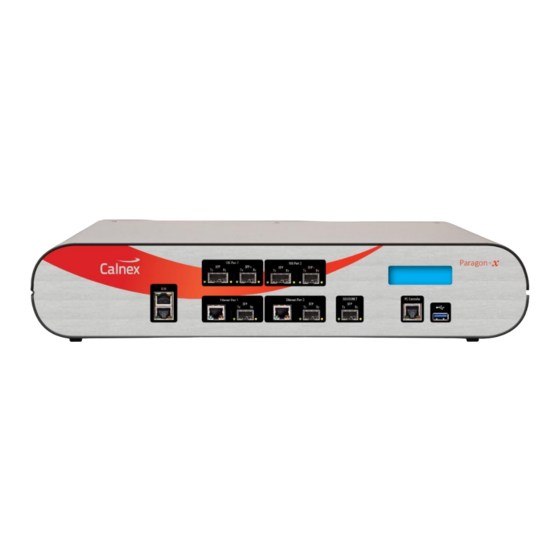
Page 5: Front Panel Description
(all cases except Master Test configuration). The 1PPS output is locked to whatever Paragon-X 1PPS reference is in use, pin 3 +ve and pin 6 GND. Both outputs use an in-line or series 50Ω resistor and can drive high impedance inputs as well as 50Ω... - Page 6 (all cases except Master Test configuration). The 1PPS output is locked to whatever Paragon-X 1PPS reference is in use, pin 3 +ve and pin 6 GND. Both outputs use an in-line or series 50Ω resistor and can drive high impedance inputs as well as 50Ω...
- Page 7 5. Display During the power up process, the display will show the Calnex logo then information regarding the IP address and port number Paragon-X is configured to use. After approx. 90s the unit will be available for operation. 6. USB port Not used.
-
Page 8: Rear Panel Description
17. GPS Reference 18. GPS Antenna Input 10. DC Power Input For connection to supplied AC power adaptor only. Power supply: AC input 100 - 240V, 1.5A, 50 - 60Hz. 11. Power Switch Paragon-X Getting Started Guide Page 8 of 28... -
Page 9: Reference Inputs
Accepts Time of Day (ToD) message input as RS-232 on pin 2 (pin 5 GND) and can generate ToD message output as RS-232 on pin 3 (pin 5 GND). Paragon-X can display ToD messages directly as received, or qualified by 1PPS signal. - Page 10 4. Use Paragon-X’s rear panel power switch, marked I/0, to switch on Paragon-X. 5. The blue display on the front panel will turn on. Paragon-X is initialised and ready to use after approximately 90 seconds. Note that on first power up, the IP address shown on the display is factory-preset and can be changed to meet your network requirement.
-
Page 11: Configuring Your Computer
PC running the Paragon-X application connected directly to the Paragon- X. The host PC has two Ethernet ports to allow connection directly to the Paragon-X and to the network. Control of Paragon-X is then enabled by a remote desktop connection to the host PC from any accessible PC. - Page 12 Windows Firewall settings may need modified to allow connection to Paragon-X as this communication requires access to the following ports. If issues are found trying when to connect to Paragon-X or run the associated software, first confirm that these ports are available:...
-
Page 13: Installing The Application Software
2. Once the installation process is complete, click on Start > All Programs > Calnex > Paragon- X to launch the Paragon-X Remote Client app as shown below (note that the path may be different if the settings were changed from default during the installation process): The software version of the Paragon-X application can be found by clicking on Help >... -
Page 14: Graphical User Interface Basics
- not active in the current configuration • Link: indicates if there is a physical Ethernet connection to Paragon-X by detecting transitions on the selected port Rx side. Good Pkts: indicates Paragon-X is receiving Ethernet packets with no PCS or checksum errors. - Page 15 Wander: indicates Paragon-X is locked to the selected wander measurement input signal (see ‘Wander Measurement Input’ rear panel connector description). • 1PPS Ref: indicates Paragon-X is locked to the 1PPS reference (see ‘1PPS and 64K AMI’ panel connector descriptions). •...
- Page 16 1. The first step is to connect to Paragon-X. Click on Start Up then Connect. 2. Enter the Paragon-X IP address and your username, if required (the default is your PC username) then click on OK. If failure to connect occurs, check your network connection and host PC network adapter settings (see details in previous section).
- Page 17 8. Click on Setup Interface to configure the ethernet interfaces, references and measurement parameters to match the requirements of the device to be tested and inputs available to Paragon-X. Note: suitable SFP/SFP+ or XFPs must be inserted into the relevant Paragon-X ports to allow the selection of the associated optical interface:...
- Page 18 All Packet Capture and Analysis in Ethernet OAM operating mode. Please refer to appropriate Calnex application notes and SUS release notes for detailed operational steps and result interpretation in relation to specific tests. These may be accessed from the Help menu in the Paragon-X application.
- Page 19 Paragon-X Constant Time Error (cTE) measurement This section details how to perform a Time Error test. This requires Paragon-X to have Opt. 250 (Master/Slave Emulation End to End) or Opt. 252 (Master/Slave Emulation Peer to Peer) fitted. 1. In Operating Mode, select 1588v2 and tick the Enable Master/Slave Emulation box.
- Page 20 7. Select Time Error Measurement from the Tools > Calnex Analysis Tool (1588v2) menu. This will start CAT, which allows the observation and analysis of data captured by the Paragon-X hardware and application. 8. When CAT launches, the Select file page is initially displayed and the live capture file pre-selected.
- Page 21 Input connector, switch it on and wait until all the LEDs are green. Then connect either the 1PPS Ref Output to the Paragon-X 1PPS rear panel connector and/or the 10M Ref Output to the Paragon-X 10MHz Reference Input rear panel connector.
-
Page 22: Power Switch
EMP protectors. This includes also the exchange of gas discharge tubes. Keep back from such activities during thunderstorms. Be aware that only a complete protection system according to IEC 62305-1 can protect your equipment and personnel against the impact of lightning. Paragon-X Getting Started Guide Page 22 of 28... - Page 23 At the end of life please dispose of the equipment through a recognized and approved scheme fulfilling the local environmental requirements. Alternatively contact Calnex Solutions Ltd to have them arrange for return and disposal.
-
Page 24: Front View
1PPS/ToD/Frequency Converter (Revision C) The Calnex external 1PPS/ToD/Frequency converter may be supplied as an option to the Paragon-X (Opt. 133) or ordered separately. Front View Functions Input Output Combined differential RJ-45 connector (see port 1PPS TTL (single-ended) pulse on RJ-45 1PPS+ToD serial signal 1 pinout above). - Page 25 1PPS/ToD/Frequency Converter (Revision D) The Calnex external 1pps/ToD/Frequency converter may be supplied as an option to the Paragon-X (Opt. 133) or ordered separately. Front View Paragon-X Getting Started Guide Page 25 of 28...
- Page 26 Weight: 320g. Power Supply: USB 5Vdc/3W direct, or via supplied 100-254Vac/47-63Hz AC adapter (if ordered standalone). Environmental Specifications: Same as Paragon-X. The peak-peak frequency input to the converter should be in the range of 200mV – 3V into 50Ω. The converter can accept either sinusoidal or square waveform.
- Page 27 This page is intentionally blank. Paragon-X Getting Started Guide Page 27 of 28...
- Page 28 Paragon-X Getting Started Guide Page 28 of 28...
Need help?
Do you have a question about the Paragon-X and is the answer not in the manual?
Questions and answers