Advertisement
Quick Links
Engineering Specification, Installation, Operation and Maintenance
Series LFM513-14 / LFM6513-14
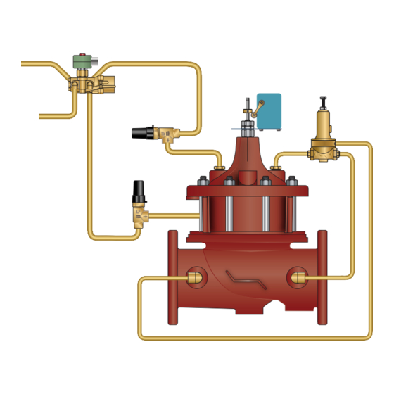
Deep Well Control Valve with Pressure Relief Feature
Sizes: 2" to 24"
WARNING
!
Read this Manual BEFORE using this equipment.
Failure to read and follow all safety and use information
can result in death, serious personal injury, property
damage, or damage to the equipment.
Keep this Manual for future reference.
WARNING
!
Local building or plumbing codes may require modifica-
tions to the information provided. You are required to
consult the local building and plumbing codes prior
to installation. If the information provided here is not
consistent with local building or plumbing codes, the
local codes should be followed. This product must be
installed by a licensed contractor in accordance with
local codes and ordinances.
WARNING
!
Need for Periodic Inspection/Maintenance: This product
must be tested periodically in compliance with local codes,
but at least once per year or more as service conditions
warrant. All products must be retested once maintenance
has been performed. Corrosive water conditions and/or
unauthorized adjustments or repair could render the product
ineffective for the service intended. Regular checking and
cleaning of the product's internal and external components
helps assure maximum life and proper product function.
NOTICE
For Australia and New Zealand: Pipeline strainers should be
installed between the upstream shutoff valve and the inlet of
the backflow preventer.
It's important that this device be tested periodically in compli-
ance with local codes, but at least once per year or more as
service conditions warrant. If installed on a fire sprinkler system,
all mechanical checks, such as alarm checks and backflow
preventers, should be flow tested and inspected internally in
accordance with NFPA 13 and NFPA 25.
Watts product specifications in U.S. customary units and metric are approximate and are provided for reference only. For precise measurements,
please contact Watts Technical Service. Watts reserves the right to change or modify product design, construction, specifications, or materials with-
out prior notice and without incurring any obligation to make such changes and modifications on Watts products previously or subsequently sold.
Submittal Package
Table of Contents
Basic Valves
Standard
Optional Components
Installation, Operation and Maintenance
Installation. . . . . . . . . . . . . . . . . . . . . . . . . . . . . . . . . . . . . . . . . . . . 15
ACV Maintenance Schedule
LFM513-14
. . . . . . . . . . . . . . . . . . . . . . . . . . . . . . . . . . . . . . . . 2
. . . . . . . . . . . . . . . . . . . . . . . . . . . . . . . . . . . . . . . . . . . 3
Components. . . . . . . . . . . . . . . . . . . . . . . . . . . . . . . . . . . 7
. . . . . . . . . . . . . . . . . . . . . . . . . . . . . . . . . . 13
. . . . . . . . . . . . . . . . . . . . . . . . . . . . . . 15
. . . . . . . . . . . . . . . . . . . . . . . . . . . . . 18
. . . . . . . . . . . . . . . . . . . . . . . . . . . . . . . . . . 19
. . . . . . . . . . . . . . . . . . . . . . . 20
ES-ACV-LFM513-14
FLOW
CLOSES VALVE
OPENS VALVE
Page
. . . . . . . . . . . . . . . . 16
(Supply Pres
Advertisement

Subscribe to Our Youtube Channel
Related Manuals for Watts LFM513-14 Series


Summary of Contents for Watts LFM513-14 Series
-
Page 1: Table Of Contents
Watts Technical Service. Watts reserves the right to change or modify product design, construction, specifications, or materials with- out prior notice and without incurring any obligation to make such changes and modifications on Watts products previously or subsequently sold. -
Page 2: Engineering Specifications
When header pressure is lowered below the pilot setting, the before beginning the installation of this product. valve closes. ES-ACV-LFM513-14 2115 © 2021 Watts... - Page 3 Deep Well Control Valve with Pressure Relief Feature Full Port Ductile Iron Dual Chamber Basic Valve This Watts ACV is a full port, dual chamber basic valve that incorporates a one-piece disc and diaphragm assembly. This assembly is the only moving part within the valve, allowing it to open or close as commanded by the pilot control system.
-
Page 4: Acv Schematic
• The C Factor of a value is the flow rate in US GPM at 60°F that will • For sizing questions including cavitation analysis consult Watts cause a 1psi drop in pressure. with system details. • factor can be used in the following equations to determine Flow (Q) and Pressure Drop (∆P):... - Page 5 ***Note: 6 inch and smaller valves, Seat Ring is threaded NOTICE Installation: If unit is installed in any orientation other than horizontal (cover up) OR extreme space constraints exist, consult customer service prior to or at the time of order. ES-ACV-LFM513-14 2115 © 2021 Watts...
- Page 6 1051 43 1105 3300 1497 Grooved End Dimensions Valve Globe Grooved Cover To Center Angle Grooved Angle Grooved Port Size Port Size Port Size Shipping Weights* Size (npt) (npt) (npt) lbs. kgs. 21⁄2 51⁄2 121⁄2 ES-ACV-LFM513-14 2115 © 2021 Watts...
- Page 7 However, brass solenoids may be used as a replacement component in a lead free Watts ACV main valve, as the wetted surface of a lead free Watts ACV main valve including installed brass solenoids contains less than 0.25% of lead by weight.
- Page 8 * The wetted surface of this product contacted by consumable water contains less than 0.25% of lead by weight. Parts List Item Description Limit Switch Bracket Stem Trip collar Set Screw Wiper Ring* O-Ring* Guide O-Ring* Polypak* Locknut Body Coupling *Included in Repair Kit ES-ACV-LFM513-14 2115 © 2021 Watts...
- Page 9 Lead Free Brass FLOW Needle: Stainless Steel (304) Elastomers: Buna-N (standard) Internal Threads * The wetted surface of this product contacted by consumable water FLOW contains less than 0.25% of lead by weight. FLOW External Threads FLOW ES-ACV-LFM513-14 2115 © 2021 Watts...
- Page 10 Jam Nut Lockwasher Spring Housing Diaphragm Washer Spring Guide Diaphragm* Spring Diaphragm Washer Cap Screw O-Ring* Power Chamber Stem 1.00 O-Ring* Retainer Inlet Outlet Body Rubber Disc* 3.50 Seat Screw O-Ring* *Included in Repair Kit ES-ACV-LFM513-14 2115 © 2021 Watts...
- Page 11 * The wetted surface of this product contacted by consumable water contains less than 0.25% of lead by weight. Dimensions SIZE DIMENSIONS WEIGHT lbs. kgs. 0.77 11/16 11/16 11/16 11/16 0.77 0.77 5/16 5/16 0.77 ES-ACV-LFM513-14 2115 © 2021 Watts...
- Page 12 Temp Rating: -40°F - 400°F * The wetted surface of this product contacted by consumable water contains less than 0.25% of lead by weight. Size Dimensions Weight lbs. 13/16 7/16 13/16 7/16 13/16 7/16 15/16 5/16 ES-ACV-LFM513-14 2115 © 2021 Watts...
- Page 13 400psi (27.6 bar) Filter Element: Monel Screen Mesh: 40 Mesh (standard) Male Pipe Thread Female Pipe Thread * The wetted surface of this product contacted by consumable water contains less than 0.25% of lead by weight. ES-ACV-LFM513-14 2115 © 2021 Watts...
- Page 14 * The wetted surface of this product contacted by consumable water contains less than 0.25% of lead by weight. Parts List Item Description Limit Switch Bracket Stem Trip collar Set Screw Wiper Ring* O-Ring* Guide O-Ring* Polypak* Locknut Body Coupling *Included in Repair Kit ES-ACV-LFM513-14 2115 © 2021 Watts...
-
Page 15: Installation
Control section of the next page. Valve Servicing Dimensions FLOW FLOW FLOW FLOW The following tables detail the recommended minimum valve servicing dimensions. Globe Size (in) 21/2 A (in) B (in) Angle Size (in) 2 1/2 C (in) D (in) ES-ACV-LFM513-14 2115 © 2021 Watts... -
Page 16: Commissioning The Deep Well Pump Control
If valve closing is too slow, turn the adjustment screw OUT, coun- terclockwise, increasing the rate of closing. Figure 2 Flow Control ES-ACV-LFM513-14 2115 © 2021 Watts... - Page 17 At valve full open position deep well pump will stop. Adjust limit switch collar to final position to ensure positive actuation of limit switch electrical contact, if necessary, by sliding up/down to loca- tion (See Figure 4). Figure 4 Limit Switch in Open Position ES-ACV-LFM513-14 2115 © 2021 Watts...
-
Page 18: Troubleshooting Guide
Automatic Control Valve Maintenance Schedule To ensure peak performance and longevity of your automatic con- • Annual Maintenance trol valve, Watts/Ames recommends following the below – Conduct monthly & quarterly inspections. standard maintenance schedule. – Inspect & clean all strainers. - Page 19 Check voltage at the solenoid Should be performed by actuate connection, insuring that it has licensed electrician the minimum of 85% of the coils rated voltage. Manual operated is engaged Turn manual operator counter- clockwise to disengage ES-ACV-LFM513-14 2115 © 2021 Watts...
-
Page 20: Valve Disassembly Instructions
2 1/2 0677-21 0677-22 0677-23 0677-24 0677-25 0677-26 Consult Factory 0677-28 0677-29 0677-30 Table 3: Reduced Port Valve (M6500 / M61500) Repair Kits Size (in) 20 & 24 0677-21 0677-23 0677-24 0677-25 0677-26 0677-27 0677-28 0677-30 ES-ACV-LFM513-14 2115 © 2021 Watts... - Page 21 Notes - LFM513-14 Limited Warranty: Watts Regulator Co. (the “Company”) warrants each product to be free from defects in material and workmanship under normal usage for a period of one year from the date of original shipment. In the event of such defects within the warranty period, the Company will, at its option, replace or recondition the product without charge.
Need help?
Do you have a question about the LFM513-14 Series and is the answer not in the manual?
Questions and answers