
Related Manuals for Green Power 600G

Summary of Contents for Green Power 600G
- Page 1 Installation Instructions / User Manual Microinverter connected to the grid photovoltaic and type designations...
- Page 2 Important safety instructions..............Safety instructions Radio interference statement for communications Symbols to replace words on equipment, displays and instructions Introduction to the microinverter system..........How microwaves maximize energy production from PV installations Less unreliable microinverters Easy installation Introduction to the microinverter............Installation of a microinverter system...........
-
Page 3: Important Safety Instructions
Important safety instructions This manual contains important information that must be followed during installation and maintenance of the grid-connected photovoltaic inverter (microinverter). To reduce the risk of electric shock and ensure safe installation and operation of the microinverter, the following symbols appear hroughout this document to indicate to hazardous conditions and important safety instructions. - Page 4 • Recommendation! The external protective ground wire is connected to the protective ground ter- minal of the inverter via the AC connector. When connecting, connect the AC connector first to ensure that the inverter is grounded, and then make the DC connection. When disconnecting, disconnect the AC power by opening the branch circuit breaker first, but keep the protective ground wire in the branch circuit breaker, connect to the inverter, and then disconnect the DC inputs.
- Page 5 Symbols replace words on equipment, displays or in instructions May be an OEM trademark. Caution risk of electric shock. Caution hot surface. Symbol for the marking of electrical and electronic equipment in accordance with Directive 2009/96/EC. Indicates that the appliance, its accessories and packaging must not be disposed of as unsorted municipal waste and must be collected separately at the end of their useful life.
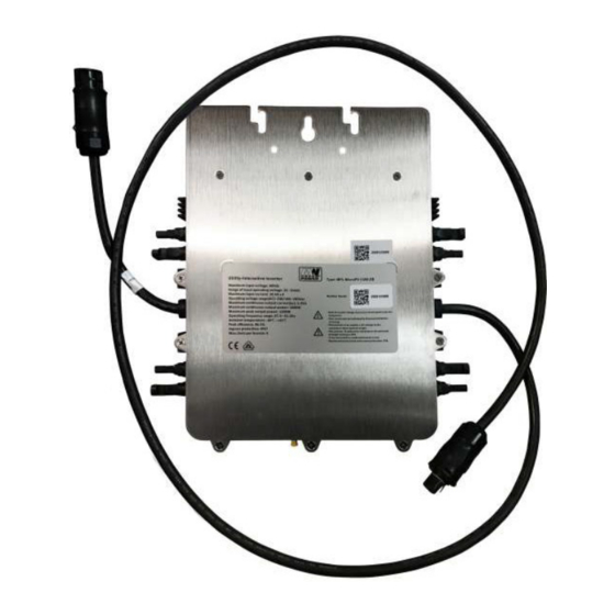
- Page 6 MPL MicroPV 600-ZB or MPL Micro PV 600-PLC MPL MicroPV 1300-ZB or MPL Micro PV 1300-PLC This integrated system improves safety; maximizes solar energy use; increases system reliability; and simplifies the design, installation, maintenance, and ma- nagement of a photovoltaic system.
- Page 7 60 and 72 cell PV modules. Please refer to the technical data page (16~21) of this manual for more information. Model Max. # per AC system ModulePV number branch 8 for 25A circuit 600G breaker 50/60Hz, 230V 60,72 cell 4 for 25A circuit 1300G braker...
-
Page 8: Microinverter Installation
Microinverter installation A PV system using microinverters is simple to install. Each microinverter can be easily mounted on a mounting system directly under the photovoltaic modules. DC wires connect the PV module directly to the microinverter which eliminates the presence of high DC voltage. Installation MUST comply with local and technical codes. - Page 9 Installation Procedures Step 1 - Install the AC splitter box a) Install the appropriate junction box in a suitable location (called a hub) near the microinverter chains. b) Connect the end of the AC cable to the junction box with a suitable choke or connector.
- Page 10 WARNING: Before installing any of the microinverters, check that the voltage at the connection point matches the voltage rating on the microinverter label. WARNING: Do not place inverters (including DC and AC connectors) in areas exposed to sun, rain, or snow. Maintain spacing between modules. Leave at least 3/4’...
- Page 11 Step 4 - Install a protective cap for the AC cable at the end of the AC cable. Step 5 - Connect microinverters to photovoltaic modules. WARNING: When the DC cables are connected the microinverter should immediately flash one quick red and three times the green LED. This will happen as soon as the cables are connected which will show that the microinverter is working properly.
-
Page 12: Troubleshooting
3. The devices should start blinking red one minute after the AC power switch is turned on. The blue LED then flashes. This means, This means they are gene- rating power normally, a faster flashing blue LED means more power is being generated. - Page 13 GFDI error A quadruple red LED indicates that the microinverter has detected a ground fault device interrupt (GFDI) error in the photovoltaic system. Unless the GFDI error is corrected, the LED will flash four times Other Faults All other faults are reported to the ECD. A list of additional faults and troubleshooting procedures can be found in the in the ECD installation and operation manual.
- Page 14 To troubleshoot a non-functioning mikiroinverter, perform the following steps in order: 1. Check that the mains voltage and frequency are within the ranges shown in the Technical Data section of this manual. 2. Check the connection to the power grid. Check that the line voltage is present at the inverter in question by removing the AC current and then the DC current.
-
Page 15: Maintenance
Maintenance No maintenance is required. Microinverter replacement Follow the procedure to replace a defective Microchip 1. Disconnect the microinverter from the photovoltaic module in the order shown below: 1.1. Disconnect the AC by turning off the branch circuit breaker. 1.2. Disconnect the AC connector of the microinverter. 1.3. - Page 16 Data sheet for microinverter 600W MPL MicroPV 600-ZB / MPL MicroPV 600-PLC Input data (DC) Recommended input power 210 ~ 400W (2 pcs.) (STC) Maximum voltage MPPT voltage range 25 ~ 55V DC operating voltage range 20 ~ 60V Maximum short-circuit current Nominal input current 10,4 x2 Output data (AC)
- Page 17 Data sheet for microinverter 1300W MPL MicroPV 1300-ZB / MPL MicroPV 1300-PLC Input data (DC) Recommended input power 210 ~ 400W (4 pcs.) (STC) Maximum voltage MPPT voltage range 25 ~ 55V DC operating voltage range 20 ~ 60V Maximum short-circuit current Nominal input current 10,4 x4 Output data (AC)
-
Page 18: Connection Diagram
Connection diagram MPL MicroPV 600-ZB / MPL MicroPV 600-PLC Example of three-phase connection diagram -16-... - Page 19 Connection diagram MPL MicroPV 600-ZB / MPL MicroPV 600-PLC Example of one-phase connection diagram -17-...
- Page 20 Connection diagram Example of three-phase connection diagram for Europe ATTENTION: If you are using our zigbee type, you only need one ECD. If you are using our PLC type, you need to install three ECDs in each phase. -18-...
- Page 21 Connection diagram Example of one-phase connection diagram -19-...
Need help?
Do you have a question about the 600G and is the answer not in the manual?
Questions and answers