Table of Contents
Advertisement
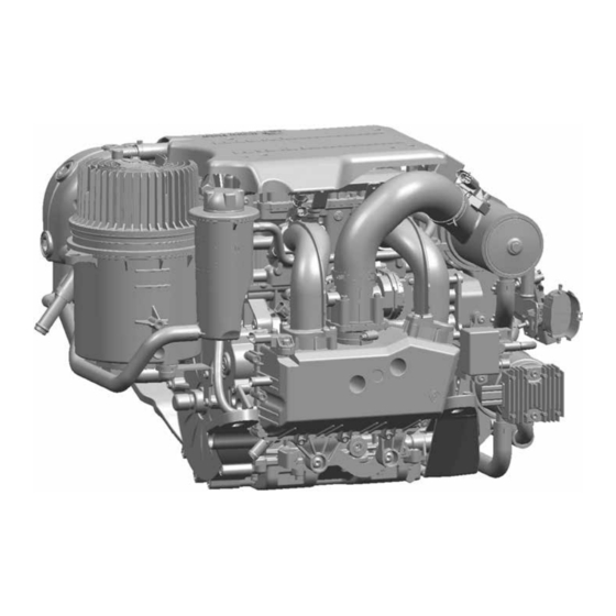
DIAGNOSTIC MANUAL
4-Stroke Engine
MPE 850 MARINE
This diagnostic manual is valid for the following engine models:
– 408101 I2 846 MAR TC-100 (TC-80) (TC-120)
– 408014 I2 846 MAR TC-120
– 408090 I2 846 MAR TC-155
– 408246 I2 846 MAR NA-80
TD407477_DHB
Rev B
06.07.2015
en_English
Read the introductory chapter before performing the task on the engine.
Pay particular attention to the safety messages.
Advertisement
Table of Contents

Related Manuals for Textron Motors MPE 850 MARINE


Summary of Contents for Textron Motors MPE 850 MARINE
- Page 1 DIAGNOSTIC MANUAL 4-Stroke Engine MPE 850 MARINE This diagnostic manual is valid for the following engine models: – 408101 I2 846 MAR TC-100 (TC-80) (TC-120) – 408014 I2 846 MAR TC-120 – 408090 I2 846 MAR TC-155 – 408246 I2 846 MAR NA-80...
- Page 3 Textron Motors GmbH strives to make continual improvements as part of the ongoing technical development of its products. All documentation is therefore subject to technical modifications. Reprints and translations, in whole or in part, require written permission from Textron Motors GmbH.
-
Page 4: Table Of Contents
5.1 Displaying trouble codes ........... . 13 5.1.1 Displaying trouble codes with Textron Motors Diagnostic Tool ..... . 13 5.1.2 Displaying trouble codes with flash codes . - Page 5 7 Wiring diagram 8 Components overview Appendix Overview of revisions ............59 Index .
-
Page 6: About This Document
The signal word Information indicates specific features and recommendations. 1.2 Change management Textron Motors GmbH strives to make continual improvements as part of the ongoing technical development of its products. Therefore descriptions in the diagnostic manual can be changed or added. All changes are described in the chapter Overview of revisions. -
Page 7: Safety
This diagnostic manual is solely intended for use in a workshop authorized by Textron Motors or the vehicle manufacturer. All work on the engine must be performed by appropriately trained personnel. -
Page 8: Important Safety Messages
All the components in your engine have been carefully tested and fulfill strict quality and safety requirements. ► Textron Motors offers spare parts to the highest quality. Ensure that equivalent spare parts corresponds with this quality requirements. Add-on parts and modifications Engine modifications may pose a safety risk to persons. - Page 9 2 Safety 2.2 Important safety messages Engine exhaust gases contain carbon monoxide (CO). Inhalation of Engine exhaust gases carbon monoxide can deprive the body of oxygen and result in organ damage or death by asphyxiation. ► Never operate the engine in enclosed spaces. Fuel, engine oil and coolant Engine fluids pose a health risk.
-
Page 10: Tools And Accessories
3 Tools and accessories 3.1 Textron Motors diagnostic case | 3.2 Equipment workshop 3 Tools and accessories 3.1 Textron Motors diagnostic case Textron Motors offers a diagnostic case that contains the following parts. Visit our web site www.weber-motor.com for more information. Figure Description... -
Page 11: Lights In Vehicle
The integrated operating hours to reset service light. (See the counter has reached the next Textron Motors Diagnostic Tool service interval. Service tasks manual.) must be performed. DHB MPE850 MAR Rev B | 408014 | 408090 | 408101 | 408246 |... -
Page 12: Malfunction Indicator Light (Mil)
4 Lights in vehicle 4.3 Malfunction indicator light (MIL) | 4.4 Temperature warning light 4.3 Malfunction indicator light (MIL) Description Cause Remedy Illuminated for a few seconds There is no malfunction. – when the ignition is switched Self test of the light. Not illuminated when the The malfunction indicator light ►... -
Page 13: Troubleshooting With Trouble Codes
► Connect the notebook to the engine und start Textron Motors Diagnostic Software. (See the Textron Motors Diagnostic Tool manual.) DHB MPE850 MAR Rev B | 408014 | 408090 | 408101 | 408246 |... -
Page 14: Displaying Trouble Codes With Flash Codes
5 Troubleshooting with trouble codes 5.1 Displaying trouble codes 5.1.2 Displaying trouble codes with flash codes Inf or ma t ion ! Each flash code is assigned to a particular trouble code. The conversion table for flash code to trouble code can be found in chapter 5.1.3 Conversion table for flash code to trouble code. The engine is not started. -
Page 15: Conversion Table For Flash Code To Trouble Code
5 Troubleshooting with trouble codes 5.1 Displaying trouble codes 5.1.3 Conversion table for flash code to trouble code Flash code Trouble code Flash code Trouble code Flash code Trouble code P2229 P0118 P2101 P2228 P0117 P2101 C0001 P0116 P2100 P0501 P0113 P2103 P0501... - Page 16 5 Troubleshooting with trouble codes 5.1 Displaying trouble codes Flash code Trouble code Flash code Trouble code Flash code Trouble code P0642 P0136 P0315 P060B P0158 P0300 P0217 P0157 P0136 P0172 P0156 P0156 P0171 P0038 P0139 P0175 P0037 P0139 P0174 P0036 P0139 P211A...
-
Page 17: Description Of Trouble Codes
5 Troubleshooting with trouble codes 5.2 Description of trouble codes 5.2 Description of trouble codes Displayed fault Affected part/system Trouble code description Possible consequences ► Possible consequences/remedy P0011 "A" Camshaft Position - Timing Over- Sensor camshaft Advanced or System Performance Bank 1 ►... - Page 18 5 Troubleshooting with trouble codes 5.2 Description of trouble codes Displayed fault Affected part/system Trouble code description Possible consequences ► Possible consequences/remedy P0032 HO2S Heater Control Circuit High Bank 1 Sensor lambda 1 Sensor 1 ► Check wiring in the wire harness to the Short circuit to plus at part or wire harness.
- Page 19 5 Troubleshooting with trouble codes 5.2 Description of trouble codes Displayed fault Affected part/system Trouble code description Possible consequences ► Possible consequences/remedy P0101 Mass or Volume Air Flow Circuit Range/ Sensor intake manifold pressure/temperature Performance ► Check wiring in the wire harness to the Implausible values in air mass calculation.
- Page 20 5 Troubleshooting with trouble codes 5.2 Description of trouble codes Displayed fault Affected part/system Trouble code description Possible consequences ► Possible consequences/remedy P0112 Intake Air Temperature Sensor 1 Circuit Low Sensor intake manifold pressure/temperature Short circuit to ground at part or wire harness. ►...
- Page 21 5 Troubleshooting with trouble codes 5.2 Description of trouble codes Displayed fault Affected part/system Trouble code description Possible consequences ► Possible consequences/remedy P0122 Throttle/Pedal Position Sensor/Switch "A" Throttle body Circuit Low ► Check wiring in the wire harness to the Open circuit or short circuit to ground at part or affected part.
- Page 22 5 Troubleshooting with trouble codes 5.2 Description of trouble codes Displayed fault Affected part/system Trouble code description Possible consequences ► Possible consequences/remedy P0132 O2 Sensor Circuit High Voltage Bank 1 Sensor lambda 1 Sensor 1 ► Check wiring in the wire harness to the Short circuit to plus at part or wire harness.
- Page 23 5 Troubleshooting with trouble codes 5.2 Description of trouble codes Displayed fault Affected part/system Trouble code description Possible consequences ► Possible consequences/remedy P0171 System Too Lean Bank 1 Sensor lambda 1 Fueling too lean. ► A leaky intake system or exhaust system can cause the fault.
- Page 24 5 Troubleshooting with trouble codes 5.2 Description of trouble codes Displayed fault Affected part/system Trouble code description Possible consequences ► Possible consequences/remedy P0217 Engine Coolant Over Temperature Condition Cooling system Coolant temperature is 100 °C [212 °F] or ► An insufficient coolant level or leaks can higher.
- Page 25 5 Troubleshooting with trouble codes 5.2 Description of trouble codes Displayed fault Affected part/system Trouble code description Possible consequences ► Possible consequences/remedy P0238 Turbo/Super Charger Boost Sensor "A" Circuit Sensor intercooler pressure High ► Check wiring in the wire harness to the Short circuit to plus at part or wire harness.
- Page 26 5 Troubleshooting with trouble codes 5.2 Description of trouble codes Displayed fault Affected part/system Trouble code description Possible consequences ► Possible consequences/remedy P025A Fuel Pump Module Control Circuit/Open Relay fuel pump Open circuit at part or wire harness. ► Check wiring in the wire harness to the affected part.
- Page 27 5 Troubleshooting with trouble codes 5.2 Description of trouble codes Displayed fault Affected part/system Trouble code description Possible consequences ► Possible consequences/remedy P0262 Cylinder 1 Injector Circuit High Injector 1st cylinder Short circuit to plus at part or wire harness. ►...
- Page 28 5 Troubleshooting with trouble codes 5.2 Description of trouble codes Displayed fault Affected part/system Trouble code description Possible consequences ► Possible consequences/remedy P0341 Camshaft Position Sensor "A" Circuit Range/ Sensor camshaft Performance Bank 1 or Single Sensor ► Check wiring in the wire harness to the No signal at the sensor camshaft.
- Page 29 5 Troubleshooting with trouble codes 5.2 Description of trouble codes Displayed fault Affected part/system Trouble code description Possible consequences ► Possible consequences/remedy P0370 Timing Reference High Resolution Signal "A" Sensor crankshaft Erratic signal at the sensor crankshaft. ► Check wiring in the wire harness to the affected part.
- Page 30 5 Troubleshooting with trouble codes 5.2 Description of trouble codes Displayed fault Affected part/system Trouble code description Possible consequences ► Possible consequences/remedy P0615 Starter Relay Circuit Relay starter Open circuit at part or wire harness. ► Check wiring in the wire harness to the affected part.
- Page 31 5 Troubleshooting with trouble codes 5.2 Description of trouble codes Displayed fault Affected part/system Trouble code description Possible consequences ► Possible consequences/remedy P0626 Generator Field/F Terminal Circuit High Voltage regulator/Generator Charging voltage too high. ► Check the voltage regulator. (See chapter 6 Test procedures at engine.) ►...
- Page 32 5 Troubleshooting with trouble codes 5.2 Description of trouble codes Displayed fault Affected part/system Trouble code description Possible consequences ► Possible consequences/remedy P063D Auto Configuration Throttle Input - Lower Throttle body position is not reached ► Check wiring in the wire harness to the affected part.
- Page 33 5 Troubleshooting with trouble codes 5.2 Description of trouble codes Displayed fault Affected part/system Trouble code description Possible consequences ► Possible consequences/remedy P0643 Sensor Reference Voltage "A" Circuit High 5 V power supply from engine control unit Short circuit to plus at 5 V power supply from ►...
- Page 34 5 Troubleshooting with trouble codes 5.2 Description of trouble codes Displayed fault Affected part/system Trouble code description Possible consequences ► Possible consequences/remedy P0659 Actuator Supply Voltage "A" Circuit High Battery The battery voltage is too high. ► Replace the battery. (See the vehicle manufacturer‘s documentation.) Engine does not start or stalls.
- Page 35 5 Troubleshooting with trouble codes 5.2 Description of trouble codes Displayed fault Affected part/system Trouble code description Possible consequences ► Possible consequences/remedy P2102 Throttle Actuator Control Motor Circuit Low Throttle body Short circuit to ground at part or wire harness. ►...
- Page 36 5 Troubleshooting with trouble codes 5.2 Description of trouble codes Displayed fault Affected part/system Trouble code description Possible consequences ► Possible consequences/remedy P2119 Throttle Actuator Control Throttle Body Range/ Throttle body Performance WARNING! The throttle body is a safety Implausible values of the sensors. critical component.
- Page 37 5 Troubleshooting with trouble codes 5.2 Description of trouble codes Displayed fault Affected part/system Trouble code description Possible consequences ► Possible consequences/remedy P2127 Throttle/Pedal Position Sensor/Switch "E" Throttle request unit Circuit Low Input ► Check wiring in the wire harness to the Open circuit or short circuit to ground at part or affected part.
- Page 38 5 Troubleshooting with trouble codes 5.2 Description of trouble codes Displayed fault Affected part/system Trouble code description Possible consequences ► Possible consequences/remedy P2262 Turbo/Super Charger Bypass Valve - Waste gate valve Mechanical ► A permanently open waste gate valve can Boost pressure permanently too low.
-
Page 39: Test Procedures At Engine
6 Test procedures at engine 6.1 Checking voltage regulator 6 Test procedures at engine 6.1 Checking voltage regulator Voltage regulator 200 mm [7.9 in] 3-pole connection at stator generator (yellow wires) 2-pole connection at battery cable (red wires) Connection engine ground inner diameter 8 mm (black wires) 600 mm [23.7 in]... -
Page 40: Checking Generator
6 Test procedures at engine 6.2 Checking generator 6.2 Checking generator Generator Stator Rotor 3-pole connection at stator generator (yellow wires) ► Check all electrical contacts for corrosion and proper mechanical connection. ► Make a continuity test with all relevant wires: Continuity test with multimeter: GX1- Engine... -
Page 41: Checking Crankshaft Reluctor
6 Test procedures at engine 6.3 Checking crankshaft reluctor 6.3 Checking crankshaft reluctor – Crankshaft reluctor – Gap (2 missing teeth) – Marking for valve timing ► Perform a visual inspection of the crankshaft reluctor. ► If mechanical defects are present, for example at the teeth, replace the crankshaft. DHB MPE850 MAR Rev B | 408014 | 408090 | 408101 | 408246 |... -
Page 42: Checking Thermostat
6 Test procedures at engine 6.4 Checking thermostat 6.4 Checking thermostat Inf or ma t ion ! The thermostat is fitted with a wax element. Opening temperature from 82 °C [179 °F] The thermostat is fully open at 88 °C [190 °F] –... -
Page 43: Checking Cam Spike At Rocker Arm
6 Test procedures at engine 6.5 Checking cam spike at rocker arm 6.5 Checking cam spike at rocker arm – Cam spike at rocker arm ► Perform a visual inspection of the cam spike at rocker arm. ► If mechanical defects are present, replace the rocker arm. DHB MPE850 MAR Rev B | 408014 | 408090 | 408101 | 408246 |... -
Page 44: Checking Oil Pressure
6 Test procedures at engine 6.6 Checking oil pressure 6.6 Checking oil pressure Inf or ma t ion ! Limited by the oil pressure valve the maximum oil pressure is 5,5 bar. ► Warm up the engine. (See the vehicle manufacturer‘s documentation.) ►... -
Page 45: Troubleshooting Guide Too Low Oil Pressure
6 Test procedures at engine 6.6 Checking oil pressure 6.6.1 Troubleshooting guide too low oil pressure Oil pressure too low Leaks in lubrication system/cylinder head Repair the leaks gasket See the repair manual. Oil pressure valve Replace the oil pressure always opened valve See the repair manual. - Page 46 7 Wiring diagram 7 Wiring diagram 7 Wiring diagram RDBK 64P-E4 BKRD 32P-F1 64P-L3 Roll Over + 5V RDGN 32P-B4 Engine control unit Roll Over SGND BKWT 32P-E3 BNYL Roll Over Signal 32P-B3 BKGN 64P-J2 Switch oil pressure BLWT 32P-F3 BLWT 64P-H4 WTRD...
- Page 47 8 Components overview 8 Components overview Engine models I2 846 MAR TC-80, TC-100 und TC-120 Engine control unit Engine model I2 846 MAR TC-155 Engine control unit Connector pin assignment: A1-64P A1-32P DHB MPE850 MAR Rev B | 408014 | 408090 | 408101 | 408246 |...
- Page 48 8 Components overview Engine models I2 846 MAR NA-80 Engine control unit Connector pin assignment: A1-64P A1-32P Switch oil pressure At the turn of 2014/2015, the installation location of the switch oil pressure was moved to the opposite side of the oil filter bracket.
- Page 49 8 Components overview Engine models I2 846 MAR TC-80, TC-100 und TC-120 Sensor intake manifold pressure/temperature Sensor intercooler pressure Engine model I2 846 MAR TC-155 Sensor intake manifold pressure/temperature Sensor intercooler pressure The sensor intercooler is installed behind the connecting pipe. Engine model I2 846 MAR NA-80 Sensor intake manifold...
- Page 50 8 Components overview Sensor crankshaft Connector pin assignment: The engine bracket is not shown in the figure. Sensor lambda 1 Or the sensor lambda 1 is installed behind the exhaust manifold. Sensor lambda 2 Connector pin assignment: Sensor camshaft Connector pin assignment: DHB MPE850 MAR Rev B | 408014 | 408090 | 408101 | 408246 |...
- Page 51 8 Components overview Sensor coolant temperature Connector pin assignment: The turbocharger is not shown in the figure. Engine models I2 846 MAR TC-80, TC-100, TC-120, TC-155 Sensor exhaust manifold temperature Hoses are not shown in the figure. Engine models I2 846 MAR NA-80 Sensor exhaust manifold temperature Connector pin assignment:...
- Page 52 8 Components overview Sensor knock Connector pin assignment: Included in fuse box X2: Fuse "FUEL", fuel pump Fuse "SERVICE" Fuse "IGK", terminal 30 key switch Fuse "VBR", terminal 30 after relay main Fuse "VBD", terminal 30 battery DHB MPE850 MAR Rev B | 408014 | 408090 | 408101 | 408246 |...
- Page 53 8 Components overview Generator Stator Rotor Connector pin assignment stator: Included in fuse box X2: Relay "MAIN", relay main Relay "FUEL", relay fuel pump DHB MPE850 MAR Rev B | 408014 | 408090 | 408101 | 408246 |...
- Page 54 8 Components overview Relay starter Starter cable at relay starter Starter Voltage regulator Connector pin assignment: The intake manifold is not shown in the figure. Connector pin assignment: 200 mm [7.9 in] 600 mm [23.7 in] Ignition coil 1st cylinder Ignition coil 2nd cylinder Connector pin assignment: “15”...
- Page 55 8 Components overview Engine models I2 846 MAR TC-80, TC-100 und TC-120 Vehicle connector "Engine-Chassis" Engine model I2 846 MAR TC-155 Vehicle connector "Engine-Chassis" Connector pin assignment: DHB MPE850 MAR Rev B | 408014 | 408090 | 408101 | 408246 |...
- Page 56 8 Components overview Engine model I2 846 MAR TC-155 Vehicle connector "Engine-Chassis" Connector pin assignment: Engine models I2 846 MAR TC-80, TC-100 und TC-120 Fuse box Connection engine ground DHB MPE850 MAR Rev B | 408014 | 408090 | 408101 | 408246 |...
- Page 57 8 Components overview Engine model I2 846 MAR TC-155 Fuse box Connection engine ground Engine model I2 846 MAR NA-80 Fuse box Connection engine ground Connector pin assignment: DHB MPE850 MAR Rev B | 408014 | 408090 | 408101 | 408246 |...
- Page 58 8 Components overview Injector 1st cylinder Injector 2nd cylinder Connector pin assignment: Engine models I2 846 MAR TC-80, TC-100, TC-120, TC-155 Valve boost pressure control Connector pin assignment: Throttle body Connector pin assignment: DHB MPE850 MAR Rev B | 408014 | 408090 | 408101 | 408246 |...
- Page 59 Appendix Overview of revisions Appendix Overview of revisions Revision Date Chapter Description Note Rev 1.0 10.01.2014 – 1st edition diagnostic manual – Rev B 06.07.2015 – Engine model 408246 added. – DHB MPE850 MAR Rev B | 408014 | 408090 | 408101 | 408246 |...
- Page 60 Appendix Index Index Sensor exhaust manifold temperature, components overview 51 Cam spike at rocker arm, check 43 Sensor intake manifold pressure/temperature, Crankshaft reluctor, check 41 components overview 49 Sensor intercooler pressure, components overview Diagnostic case, overview 10 Sensor knock, components overview 52 Diagnostic connector, engine 13 Sensor lambda 1, components overview 50 Sensor lambda 2, components overview 50...
Need help?
Do you have a question about the MPE 850 MARINE and is the answer not in the manual?
Questions and answers